EP0185201A1 - Tiroir en matière plastique - Google Patents
Tiroir en matière plastique Download PDFInfo
- Publication number
- EP0185201A1 EP0185201A1 EP19850114465 EP85114465A EP0185201A1 EP 0185201 A1 EP0185201 A1 EP 0185201A1 EP 19850114465 EP19850114465 EP 19850114465 EP 85114465 A EP85114465 A EP 85114465A EP 0185201 A1 EP0185201 A1 EP 0185201A1
- Authority
- EP
- European Patent Office
- Prior art keywords
- holding
- drawer
- drawer according
- guide rails
- recesses
- Prior art date
- Legal status (The legal status is an assumption and is not a legal conclusion. Google has not performed a legal analysis and makes no representation as to the accuracy of the status listed.)
- Granted
Links
- 229920003023 plastic Polymers 0.000 title claims abstract description 4
- 239000004033 plastic Substances 0.000 title claims abstract description 4
- 239000000463 material Substances 0.000 title abstract 2
- 239000002184 metal Substances 0.000 claims abstract description 4
- 238000013459 approach Methods 0.000 claims description 3
- 238000006073 displacement reaction Methods 0.000 claims description 3
- 230000006978 adaptation Effects 0.000 description 1
- 238000004519 manufacturing process Methods 0.000 description 1
- 238000003466 welding Methods 0.000 description 1
Images

Classifications
-
- A—HUMAN NECESSITIES
- A47—FURNITURE; DOMESTIC ARTICLES OR APPLIANCES; COFFEE MILLS; SPICE MILLS; SUCTION CLEANERS IN GENERAL
- A47B—TABLES; DESKS; OFFICE FURNITURE; CABINETS; DRAWERS; GENERAL DETAILS OF FURNITURE
- A47B88/00—Drawers for tables, cabinets or like furniture; Guides for drawers
- A47B88/40—Sliding drawers; Slides or guides therefor
- A47B88/423—Fastening devices for slides or guides
- A47B88/427—Fastening devices for slides or guides at drawer side
-
- A—HUMAN NECESSITIES
- A47—FURNITURE; DOMESTIC ARTICLES OR APPLIANCES; COFFEE MILLS; SPICE MILLS; SUCTION CLEANERS IN GENERAL
- A47B—TABLES; DESKS; OFFICE FURNITURE; CABINETS; DRAWERS; GENERAL DETAILS OF FURNITURE
- A47B88/00—Drawers for tables, cabinets or like furniture; Guides for drawers
- A47B88/40—Sliding drawers; Slides or guides therefor
- A47B88/423—Fastening devices for slides or guides
- A47B88/427—Fastening devices for slides or guides at drawer side
- A47B2088/4278—Quick-release clip
Definitions
- the invention relates to a drawer from; Plastic with metal guide rails clamped to it, the drawer having holding devices at several points in the edge region of the floor and / or side walls, which cooperate with holding devices or clamping devices on the guide rails.
- the invention is therefore based on the object of providing a connection between the drawer and guide rails, in which the connection between the two parts is to be easy to produce but nevertheless also transport-resistant, and different guide rails can be fitted in drawers of identical design.
- the drawer has pockets open towards the side walls, that holding parts are inserted into the pockets, which have a latching element and recesses that are resiliently transverse to the direction of displacement, and that the holding elements of the holding devices of the guide rails into the recesses of the Intervene holding parts.
- the holding parts are also identical to one another, in such a way that different guide rails can be attached to the drawers with their help.
- a guide rail 1 and a drawer 2 and in part a holding part 3 is shown in part.
- Another exemplary embodiment of a guide rail is designated as a whole by 4.
- the guide rail 1 generally has a Z-profile with a web 5, a support flange 6 and a running flange 7. At intervals from one another, the profile web 5 and the supporting flange 6 have holding devices 8, in the area of which the running flange is provided with cutouts 9.
- the holding devices comprise protruding, hook-like projections 10 of the supporting flange 6 and recesses 11 in the profile web 5.
- the guide rail 4 is a so-called telescopic guide rail with roller guides. Of this, only the base plate 12 is shown with an attached holding device 13.
- the holding device comprises an elongated support plate 25 which is connected to the base plate 12, for example by welding.
- This support plate is essential Lichen formed as an angle profile, which has the lugs 1o of the previous embodiment corresponding to projecting lugs 15 on a retaining flange 14.
- a spring tongue 16 is formed on the support plate 25, the lower end of which lies adjacent to a recess 25a in the support plate.
- the drawer 2 has side walls 17 and a base 18 which is stiffened by means of diagonally or transversely running ribs 20 and longitudinal ribs 21.
- Pockets 21 are formed at intervals from one another between a lower floor level and the side walls 17, which are delimited by boundary ribs 22 and are partially closed towards the floor level by a web 23 integrally connected to the boundary ribs.
- the pockets 21 are essentially T-shaped in plan and have locking knobs 24 on their base. Instead or in addition, locking knobs 24a can also be formed on the inside of the web 23.
- the holding part 3 shown in the drawings consists of a flat element 26 which is approximately T-shaped in plan with an enlarged longitudinal web 27 and a transverse web 28.
- an elongated recess 29 is provided so that a front web 3o is formed on the outer end face of the holding part 3, which can spring inwards.
- the front web 3o carries an outstanding Approach 31.
- the longitudinal web 27 is provided with an elongate recess 32 running parallel to the recess 29.
- the short longitudinal web 27 forms a recess 33 on both sides opposite the side surfaces of the cross web, which is delimited by the rear surfaces 34 of the cross web 28.
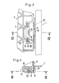
- FIGS 3 and 4 show the details explained above in the fully assembled state.
- the holding parts 3 fit into the pockets 21 in a form-fitting or almost form-fitting manner.
- the locking elements 24 connected to the drawer engage in the cutouts 32 and prevent unwanted removal of the holding parts from the pockets, which in the exemplary embodiment shown are formed below the base plate 18 of the drawer within the system of stiffening ribs.
- the holding parts fit between the base plate and the webs 23.
- the recesses 11 in the holding devices of the guide rails 1 so! are trained so that they can be used easily j and then snap into place.
- a front web 30 can only be elastically deformed to such an extent that the projection 31 disengages from the recess 11 only by applying strong pressure to the end face of the projections 31 using a screwdriver or another suitable tool.
- the protruding lugs 10 of the holding devices in the guide rails engage in the recess 33, which are formed between the limiting ribs 22 of the pockets and the rear surface 34 of the transverse web 28 of each holding part 3.
- These recesses 33 can also be formed in the holding part 3 itself within the scope of the inventive concept. In this case, only the layout of the pockets, i.e. the course of the boundary ribs 22 to be different.
- the sectional view according to FIG. 4 shows that the connection between the guide rails and the drawer is absolutely firm in both directions perpendicular to the base plate 18 of the drawer (arrow directions 35).
- connection to the drawer is similar to the example shown in Figure 4.
- the free lower edge of the spring tongue 16 is supported on the upper side of the front web 3o of the holding part 3.
- this spring tongue 16 must be pressed into the plane of the flange 25 by means of a suitable tool and the front web 3o must be pressed out of the recess 25a in the sense of the above description in order to separate the drawer and the guide rail.
- the connection between the drawer and the guide rail can be loaded in both directions perpendicular to the base plate of the drawer.
Landscapes
- Drawers Of Furniture (AREA)
Priority Applications (1)
| Application Number | Priority Date | Filing Date | Title |
|---|---|---|---|
| AT85114465T ATE90849T1 (de) | 1984-12-15 | 1985-11-14 | Schubkasten aus kunststoff. |
Applications Claiming Priority (2)
| Application Number | Priority Date | Filing Date | Title |
|---|---|---|---|
| DE3445880 | 1984-12-15 | ||
| DE3445880A DE3445880C2 (de) | 1984-12-15 | 1984-12-15 | Schubkasten aus Kunststoff |
Publications (2)
| Publication Number | Publication Date |
|---|---|
| EP0185201A1 true EP0185201A1 (fr) | 1986-06-25 |
| EP0185201B1 EP0185201B1 (fr) | 1993-06-23 |
Family
ID=6252918
Family Applications (1)
| Application Number | Title | Priority Date | Filing Date |
|---|---|---|---|
| EP85114465A Expired - Lifetime EP0185201B1 (fr) | 1984-12-15 | 1985-11-14 | Tiroir en matière plastique |
Country Status (3)
| Country | Link |
|---|---|
| EP (1) | EP0185201B1 (fr) |
| AT (1) | ATE90849T1 (fr) |
| DE (1) | DE3445880C2 (fr) |
Cited By (3)
| Publication number | Priority date | Publication date | Assignee | Title |
|---|---|---|---|---|
| EP0320585A1 (fr) * | 1987-12-12 | 1989-06-21 | Gustav Ziehl Firma | Tiroir métallique |
| EP0972468A3 (fr) * | 1998-07-07 | 2001-12-05 | Accuride International Limited | Glissière de tiroir et tiroir incorporant un accouplement rapide |
| WO2006120074A1 (fr) * | 2005-05-10 | 2006-11-16 | BSH Bosch und Siemens Hausgeräte GmbH | Dispositif de tablettes telescopiques |
Families Citing this family (3)
| Publication number | Priority date | Publication date | Assignee | Title |
|---|---|---|---|---|
| DE19541767B4 (de) * | 1995-11-09 | 2004-09-23 | Grass Gmbh | Schubladenschiene und Verfahren zu deren Herstellung |
| US6378967B1 (en) | 2000-08-29 | 2002-04-30 | Grass America, Inc. | Clamp-on drawer slide |
| DE20204724U1 (de) | 2002-03-25 | 2002-05-29 | Arturo Salice S.P.A., Novedrate, Como | Vorrichtung zum Befestigen einer Tragplatte an einem Bauteil |
Citations (3)
| Publication number | Priority date | Publication date | Assignee | Title |
|---|---|---|---|---|
| DE2202312A1 (de) * | 1972-01-19 | 1973-10-04 | Thoma Kg Robert | Befestigung von schubladen od.dgl. in schreibtischen usw |
| AT334569B (de) * | 1975-03-28 | 1976-01-25 | Grass Alfred Metallwaren | Befestigung von fuhrungsschienen an schubladen |
| DE2708167A1 (de) * | 1977-02-25 | 1978-08-31 | Duepree Hans Werner | Schublade aus kunststoff |
Family Cites Families (5)
| Publication number | Priority date | Publication date | Assignee | Title |
|---|---|---|---|---|
| DE7245255U (de) * | 1973-03-08 | Thoma R Ohg | Schublade od. dgl | |
| DE7225383U (de) * | 1972-10-19 | Varta-Plastic Gmbh | Kunststoffschublade mit Bodenverstärkung | |
| DE1995629U (de) * | 1968-04-06 | 1968-10-31 | Becher & Co Moebelfabriken K G | Halteduebel zum halten von fuehrungsleisten fuer schubladen, zwischenbrettern, oder dergl. in moebelteilen. |
| DE8114990U1 (de) * | 1981-05-20 | 1982-08-05 | Fa. Gustav Ziehl, 5000 Köln | Moebel mit schubladenauszug |
| DE8320567U1 (de) * | 1983-07-16 | 1983-11-24 | Bbp-Kunststoffwerk Marbach Baier & Co, 7142 Marbach | Schubkasten aus kunststoff fuer moebel |
-
1984
- 1984-12-15 DE DE3445880A patent/DE3445880C2/de not_active Expired - Fee Related
-
1985
- 1985-11-14 AT AT85114465T patent/ATE90849T1/de not_active IP Right Cessation
- 1985-11-14 EP EP85114465A patent/EP0185201B1/fr not_active Expired - Lifetime
Patent Citations (3)
| Publication number | Priority date | Publication date | Assignee | Title |
|---|---|---|---|---|
| DE2202312A1 (de) * | 1972-01-19 | 1973-10-04 | Thoma Kg Robert | Befestigung von schubladen od.dgl. in schreibtischen usw |
| AT334569B (de) * | 1975-03-28 | 1976-01-25 | Grass Alfred Metallwaren | Befestigung von fuhrungsschienen an schubladen |
| DE2708167A1 (de) * | 1977-02-25 | 1978-08-31 | Duepree Hans Werner | Schublade aus kunststoff |
Cited By (5)
| Publication number | Priority date | Publication date | Assignee | Title |
|---|---|---|---|---|
| EP0320585A1 (fr) * | 1987-12-12 | 1989-06-21 | Gustav Ziehl Firma | Tiroir métallique |
| EP0972468A3 (fr) * | 1998-07-07 | 2001-12-05 | Accuride International Limited | Glissière de tiroir et tiroir incorporant un accouplement rapide |
| WO2006120074A1 (fr) * | 2005-05-10 | 2006-11-16 | BSH Bosch und Siemens Hausgeräte GmbH | Dispositif de tablettes telescopiques |
| RU2387357C2 (ru) * | 2005-05-10 | 2010-04-27 | Бсх Бош Унд Сименс Хаусгерете Гмбх | Телескопическое выдвижное устройство |
| US8708436B2 (en) | 2005-05-10 | 2014-04-29 | Bsh Bosch Und Siemens Hausgeraete Gmbh | Arrangement of telescopic extensions |
Also Published As
| Publication number | Publication date |
|---|---|
| DE3445880C2 (de) | 1994-05-11 |
| ATE90849T1 (de) | 1993-07-15 |
| EP0185201B1 (fr) | 1993-06-23 |
| DE3445880A1 (de) | 1986-06-19 |
Similar Documents
| Publication | Publication Date | Title |
|---|---|---|
| DE2623709A1 (de) | Bauelementensatz | |
| EP1261785A1 (fr) | Liaison mecanique de panneaux | |
| DE2104050C3 (de) | Klemmhalterung | |
| DE3902399A1 (de) | Zierleistenhalter | |
| DE3709970C2 (fr) | ||
| EP0185201A1 (fr) | Tiroir en matière plastique | |
| DE69614237T2 (de) | Befestigungssystem für eine Kraftfahrzeuginnenverkleidung | |
| DE7602860U1 (de) | Halter für Kabelkanäle | |
| EP0297089B1 (fr) | Support de panneau pour panneaux d'affichages, de prix ou dispositifs similaires | |
| DE8308744U1 (de) | Werkzeug-lagereinrichtung | |
| DE202022101188U1 (de) | Regalsystem | |
| DE3742428A1 (de) | Vorrichtung zur aufnahme einer kennzeichentafel | |
| DE2100879C3 (de) | Kassettenschild | |
| DE19620709C5 (de) | Möbelfußsystem | |
| WO2006092156A1 (fr) | Element paroi | |
| DE2547887B2 (de) | Gleitführung für einen Schiebesitz für Fahrzeuge | |
| DE8500141U1 (de) | Durchlaufregal | |
| DE4204387A1 (de) | Blechschubkasten | |
| DE29922006U1 (de) | Verbindungselement für Trennwände zur Facheinteilung einer Schublade | |
| CH653793A5 (de) | Halter fuer nummerntafel. | |
| DE4211324A1 (de) | Vorrichtung zur Aufnahme eines Tafelelements | |
| DE29609198U1 (de) | Druckverschluß für das lösbare Verbinden zweier Bauteile | |
| DE20009471U1 (de) | Modulares Unterteilungssystem für Schubkästen | |
| DE102012100833B3 (de) | Achsträgervorrichtung für eine Achse eines schwenkbaren Ablageelements an einem Einkaufswagenfahrgestell und Einkaufswagen | |
| EP3552524B1 (fr) | Distributeur pour d'avancement de la marchandises |
Legal Events
| Date | Code | Title | Description |
|---|---|---|---|
| PUAI | Public reference made under article 153(3) epc to a published international application that has entered the european phase |
Free format text: ORIGINAL CODE: 0009012 |
|
| AK | Designated contracting states |
Kind code of ref document: A1 Designated state(s): AT BE CH FR GB IT LI NL SE |
|
| 17P | Request for examination filed |
Effective date: 19861124 |
|
| 17Q | First examination report despatched |
Effective date: 19880714 |
|
| GRAA | (expected) grant |
Free format text: ORIGINAL CODE: 0009210 |
|
| AK | Designated contracting states |
Kind code of ref document: B1 Designated state(s): AT BE CH FR GB IT LI NL SE |
|
| PG25 | Lapsed in a contracting state [announced via postgrant information from national office to epo] |
Ref country code: SE Effective date: 19930623 |
|
| REF | Corresponds to: |
Ref document number: 90849 Country of ref document: AT Date of ref document: 19930715 Kind code of ref document: T |
|
| GBT | Gb: translation of ep patent filed (gb section 77(6)(a)/1977) |
Effective date: 19930630 |
|
| ET | Fr: translation filed | ||
| ITF | It: translation for a ep patent filed | ||
| PLBE | No opposition filed within time limit |
Free format text: ORIGINAL CODE: 0009261 |
|
| STAA | Information on the status of an ep patent application or granted ep patent |
Free format text: STATUS: NO OPPOSITION FILED WITHIN TIME LIMIT |
|
| 26N | No opposition filed | ||
| PGFP | Annual fee paid to national office [announced via postgrant information from national office to epo] |
Ref country code: NL Payment date: 19951130 Year of fee payment: 11 Ref country code: BE Payment date: 19951130 Year of fee payment: 11 |
|
| PG25 | Lapsed in a contracting state [announced via postgrant information from national office to epo] |
Ref country code: BE Effective date: 19961130 |
|
| BERE | Be: lapsed |
Owner name: VARTA-PLASTIC G.M.B.H. Effective date: 19961130 |
|
| PG25 | Lapsed in a contracting state [announced via postgrant information from national office to epo] |
Ref country code: NL Effective date: 19970601 |
|
| NLV4 | Nl: lapsed or anulled due to non-payment of the annual fee |
Effective date: 19970601 |
|
| PGFP | Annual fee paid to national office [announced via postgrant information from national office to epo] |
Ref country code: CH Payment date: 19981015 Year of fee payment: 14 |
|
| PGFP | Annual fee paid to national office [announced via postgrant information from national office to epo] |
Ref country code: AT Payment date: 19981030 Year of fee payment: 14 |
|
| PGFP | Annual fee paid to national office [announced via postgrant information from national office to epo] |
Ref country code: GB Payment date: 19981113 Year of fee payment: 14 |
|
| PGFP | Annual fee paid to national office [announced via postgrant information from national office to epo] |
Ref country code: FR Payment date: 19991102 Year of fee payment: 15 |
|
| PG25 | Lapsed in a contracting state [announced via postgrant information from national office to epo] |
Ref country code: GB Free format text: LAPSE BECAUSE OF NON-PAYMENT OF DUE FEES Effective date: 19991114 Ref country code: AT Free format text: LAPSE BECAUSE OF NON-PAYMENT OF DUE FEES Effective date: 19991114 |
|
| PG25 | Lapsed in a contracting state [announced via postgrant information from national office to epo] |
Ref country code: LI Free format text: LAPSE BECAUSE OF NON-PAYMENT OF DUE FEES Effective date: 19991130 Ref country code: CH Free format text: LAPSE BECAUSE OF NON-PAYMENT OF DUE FEES Effective date: 19991130 |
|
| GBPC | Gb: european patent ceased through non-payment of renewal fee |
Effective date: 19991114 |
|
| REG | Reference to a national code |
Ref country code: CH Ref legal event code: PL |
|
| PG25 | Lapsed in a contracting state [announced via postgrant information from national office to epo] |
Ref country code: FR Free format text: LAPSE BECAUSE OF NON-PAYMENT OF DUE FEES Effective date: 20010731 |
|
| REG | Reference to a national code |
Ref country code: FR Ref legal event code: ST |