EP0185204A2 - Robinet-vanne - Google Patents
Robinet-vanne Download PDFInfo
- Publication number
- EP0185204A2 EP0185204A2 EP85114582A EP85114582A EP0185204A2 EP 0185204 A2 EP0185204 A2 EP 0185204A2 EP 85114582 A EP85114582 A EP 85114582A EP 85114582 A EP85114582 A EP 85114582A EP 0185204 A2 EP0185204 A2 EP 0185204A2
- Authority
- EP
- European Patent Office
- Prior art keywords
- notches
- guide
- slide
- notch
- groove
- Prior art date
- Legal status (The legal status is an assumption and is not a legal conclusion. Google has not performed a legal analysis and makes no representation as to the accuracy of the status listed.)
- Withdrawn
Links
Images

Classifications
-
- F—MECHANICAL ENGINEERING; LIGHTING; HEATING; WEAPONS; BLASTING
- F16—ENGINEERING ELEMENTS AND UNITS; GENERAL MEASURES FOR PRODUCING AND MAINTAINING EFFECTIVE FUNCTIONING OF MACHINES OR INSTALLATIONS; THERMAL INSULATION IN GENERAL
- F16K—VALVES; TAPS; COCKS; ACTUATING-FLOATS; DEVICES FOR VENTING OR AERATING
- F16K25/00—Details relating to contact between valve members and seats
- F16K25/02—Arrangements using fluid issuing from valve members or seats
-
- F—MECHANICAL ENGINEERING; LIGHTING; HEATING; WEAPONS; BLASTING
- F16—ENGINEERING ELEMENTS AND UNITS; GENERAL MEASURES FOR PRODUCING AND MAINTAINING EFFECTIVE FUNCTIONING OF MACHINES OR INSTALLATIONS; THERMAL INSULATION IN GENERAL
- F16K—VALVES; TAPS; COCKS; ACTUATING-FLOATS; DEVICES FOR VENTING OR AERATING
- F16K3/00—Gate valves or sliding valves, i.e. cut-off apparatus with closing members having a sliding movement along the seat for opening and closing
- F16K3/30—Details
- F16K3/316—Guiding of the slide
-
- Y—GENERAL TAGGING OF NEW TECHNOLOGICAL DEVELOPMENTS; GENERAL TAGGING OF CROSS-SECTIONAL TECHNOLOGIES SPANNING OVER SEVERAL SECTIONS OF THE IPC; TECHNICAL SUBJECTS COVERED BY FORMER USPC CROSS-REFERENCE ART COLLECTIONS [XRACs] AND DIGESTS
- Y10—TECHNICAL SUBJECTS COVERED BY FORMER USPC
- Y10T—TECHNICAL SUBJECTS COVERED BY FORMER US CLASSIFICATION
- Y10T137/00—Fluid handling
- Y10T137/4238—With cleaner, lubrication added to fluid or liquid sealing at valve interface
- Y10T137/4245—Cleaning or steam sterilizing
- Y10T137/4273—Mechanical cleaning
Definitions
- the invention relates to a flat slide valve, in particular for shutting off conveying lines carrying thick, dust-like or granular media, with a guide groove for the slide plate provided in the slide housing, the guide groove laterally delimiting flow channel of the slide projecting into the circular cross section having at least two successive pairs of guide strips Have pairs of notches which, when the slide plate is closed with shear edges at the lower closing edge of the slide plate, have interacting scraping edges.
- a flat slide valve of this type is described, for example, in CH patent specification « (6908/81).
- the notches of each pair of notches are aligned with one another in the flow direction.
- the slide medium flushes through the notches that are aligned with one another and the groove area lying in between, while the groove area lying between the notch pairs forms a practically flow-free storage space in which solids can accumulate.
- Such solids of the medium which are deposited in particular on the guide surfaces of the guide strips interrupted by the notches, can be mechanically pushed downwards when the slide is closed by the shear edges of the slide plate and, in cooperation with the scraping edges of the notches, can be stripped into the latter, where they are caught and flowed by the media flow rinsed downstream.
- the deposits mentioned can solidify in the areas of the guide groove lying between the notch pairs and build up to such thick layers that a considerable amount of force is required when the slide is subsequently closed in order to scrape off these deposits; the proper closing of the slide plate guided with as little play as possible can be hindered.
- the scraping of stuck deposits can also lead to damage to the guide surfaces of the guide strips over time.
- the present invention therefore aims to provide a flat slide valve of the type mentioned, in which deposits on the parts of the guide groove lying between the notches and in particular on the guide surfaces of the guide strips are largely impossible, and also in the case of longer open times of the slide valve, the build-up of relatively thick, tight deposit layers can be avoided.
- this is to be achieved in that, in particular in the region of the guide strips delimiting the guide groove and provided with notches, self-cleaning is established by the medium flow.
- the flat slide according to the invention is characterized in that the notches in one guide bar of each pair of guide bars are arranged offset from those in the other guide bar
- each notch of one guide rail is at least a part of the guide surface opposite the other guide rail; In the open position of the slide, this has the result that medium penetrating through the notches of the inflow-side guide bar into the guide groove is deflected by the opposite guide surface part in the longitudinal direction of the guide groove before it leaves the guide groove again by a notch in the outflow-side guide bar. This medium covers the part of the guide groove lying between the offset notches, so that no thicker layers of deposits can form on the relevant guide surfaces.
- the offset of the notches corresponds approximately to the size of the largest notch opening width (e), whereby the optimal flushing of the guide groove is achieved when the largest opening width of the notches is approximately the same or only slightly larger than half the notch pitch, '' the depth of the Notches are expediently somewhat smaller than the depth of the guide groove delimited on the inside by a seal.
- the cross section of the notches in a plane parallel to the slide plate is expediently wedge-shaped or U-shaped, but can also be triangular or rectangular, with all the notches having the same cross cut surface, but in order to ensure, especially in the case of larger slides, with relatively long notched guide groove parts above the slide passage that when the slide closes from these groove parts, deposits pushed down from the sheared edges of the slide plate from the notches closest to these groove parts actually picked up and rinsed out there in the passage, it may be appropriate to make these upper notches somewhat larger than the others.
- the lower slider plate edge which is offset in the transverse direction and provided with the shear edges, is expediently partially cylindrical, its diameter being somewhat larger than the plate width.
- the critical point is always the lower sealing part, which is more or less aligned with the passage and cooperates with the apex part of the slide plate.
- the seal here expediently lies in a groove of the inflow-side housing part narrowed towards the passage, the part of the outflow-side housing part delimiting this groove on the outflow side expediently protruding by a few millimeters into the cylindrical passage in order to serve as a stop for the lower slide plate edge in the closed position.
- This stop surface lying in the inflow direction immediately behind the groove containing the seal acts in the open position of the slide as a baffle, which can lead to deposits in front of this baffle in the area of the seal.
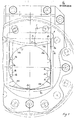
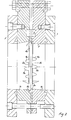
- the flat slide valve shown has a two-part housing 1a, 1b with a cylindrical flow channel 2.
- the housing parts 1a, 1b can be screwed together as shown with additional flanges 3 (for special flange bores).
- a recess 4 that surrounds the flow channel 2 in a U-shape is provided in the inflow-side housing part 1 a.
- the narrowed part 4a of the recess 4 serves as a sealing groove for receiving a seal 5, which in be known way leads to the area of a transverse seal 6.
- the enlarged part 4b of the recess 4 serves as a guide groove for the slide plate 7.
- This guide groove 4b is laterally delimited by pairs of guide strips 8a, 8b which protrude into the flow channel 2, where the outer sides thereof are chamfered in order to form baffles or undercuts which do not inhibit flow.
- Each of these pairs of guide strips 8a, 8b has, in the example shown, three notch pairs 9a, 9b arranged at a distance from one another, the notches 9a of one guide strip 8a being offset relative to one another in the flow direction relative to the notches 9b of the other guide strip 8b.
- the notch pitch t is approximately twice as large as the opening width e of the notches, while the notch depth b is somewhat less than the depth of the guide groove 4b, so that it is also at the notched points .
- the offset v of the notches of the one guide bar to the notches of the other guide bar suitably corresponds approximately to the opening width of the notches.
- the number, size, pitch and offset of the notches can vary depending on the size of the slide, ie the diameter of the flow channel 2.
- the notch pitch t is expediently between 20 and 25 mm
- the notch offset v between 8 and 12 mm
- the notch depth b between 7 and 10 mm (with a groove depth between 9 and 12 mm)
- the notch opening width e between 10 and 15 mm.
- the cross section of the notches parallel to the guide plane is wedge-shaped with a strongly rounded groove floor of adjacent end section; expediently the inner sharp notch edges diverge towards the notch opening at an angle between 5 and 15 ° (FIG. 1); however, they could also run parallel to one another at the notch opening.
- the lateral guide grooves 4b are led upwards from the area of the passage channel 2 to a segment-shaped transverse groove section 4c lying directly under the transverse seal 6, while it ends below outside the passage channel 2, but at a distance above the segment-shaped bottom section of the sealing groove 4a.
- the housing parts lying at the top between the guide grooves 4b and 4c and at the bottom between the guide grooves 4b and the sealing groove 4a are excluded from the passage, forming sink corners 10a and 10b.
- the lower apex of the inner wall of the outflow-side housing part 1b delimiting the passage channel 2 is designed to rise slightly towards the parting plane of the housing parts, so that it is a few mm at the apex of the passage channel, in practice depending on the nominal width of the slide 2 to 5 mm protrudes.
- This protruding wall section 2a serves the lower closing edge 11 of the slide plate 7 in its closed position as a stop.
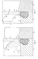
- This segment-shaped closing edge 11 has a somewhat larger diameter than the plate width, so that its partially cylindrical lower surface 11a forms an edge 12a with the narrow sides 7a of the plate 7.
- the closing edge 11 of the slide plate 7 is also offset in the direction of the plate thickness, the offset being formed by a groove 11b and by a correspondingly curved edge 12b which continues the edge 12a Narrow side 7a of the slide plate 7 merges (Fig. 5).
- the groove 11b of the closing edge 11 of the slide plate 7 is directed upstream.
- the stepped upstream edge of the closing edge 11 runs, except for short end sections 12c, in the same way as the lower edge of the surface 11a; the mentioned end sections 12c, on the other hand, are concavely curved and end in the lateral fillet edge 12b.
- These end sections 12c form shear edges for cooperation with the inner edges 13 of the notches 9a, 9b which act as wiping edges.
- the end sections 12c can also not be bent concavely, but instead can be guided to the narrow side of the plate following the curvature of the offset edge.
- the closing edge 11 of the slide plate 7 (FIG. 1 left), which is only a small height due to the relatively large diameter, lies directly above the apex of the passage channel 2 and at a small distance from the transverse seal 6.
- the segment shape of the closing edge 11 the arc shape of the lower edge of the guide groove part 4c and the bottom part of the sealing groove 4a. This not only leads to relatively small upper and lower sink corners 10a, 10b, but also allows a relatively low overall height of the upper guide part of the slide plate to be maintained.
- the edge portions of the closing edge 11 push the scraped-off deposits down in the guide grooves, where they reach the area of the first pair of notches 9a, 9b and are stripped into these notches in the interaction of the sheared edges 12c with the scraping edges 13 of the notches; analogously, deposits are scraped off in the guide groove sections lying between the notches and scraped into the subsequent pair of notches or into the lower sink corners. Since the notches 9a, 9b as well as the upper and lower sink corners are exposed to the medium flow, the accruing deposits during the closing process are continuously blown out of the notches or sink corners during pneumatic operation, respectively. ejected and washed away during hydraulic operation.
- the offset of the notches 9a with respect to the notches 9b, on the other hand, in the open position of the slide plate 7 has the effect that parts of the medium flow which penetrate through the inflow-side notches 9a of the one guide bar 8a into the guide groove 4b, are deflected in the latter and only after one of the brushes has been brushed on Notch offset corresponding groove section can leave this again by the nearest notch 9b of the other guide bar 8b.
- This continuous coating of parts of the guide surfaces of the guide groove prevents thicker layers of deposits that are difficult to scrape from forming on these guide surfaces. This ensures effective self-cleaning not only in the area of the upper and lower sink corners 10a, 10b but also within the lateral guide grooves 4b located in the area of the passage channel 2.
- the notches of the uppermost pair of notches can also be selected to be somewhat larger, so that they are larger Amounts of deposits scraped in the upper guide groove area can absorb.
- a particularly sensitive point with regard to deposits that can hinder the flawless closure of the slide plate is the lower apex of the passage 2, where the protruding wall portion 2a creates a kind of dead space on the inflow side, in which deposits are almost unavoidable.
- the pronounced fillet surface 11b of the closing edge 11 of the plate 7 immediately before closing causes the medium striking this fillet surface to be deflected into a strong downward vortex which is readily capable of deposits to blow out or flush out said dead space back into the remaining medium flow. This also ensures effective self-cleaning, which enables the slide to close properly when the slide plate 7 is lowered further (FIG. 5).
Landscapes
- Engineering & Computer Science (AREA)
- General Engineering & Computer Science (AREA)
- Mechanical Engineering (AREA)
- Sliding Valves (AREA)
- Bearings For Parts Moving Linearly (AREA)
- Details Of Valves (AREA)
Applications Claiming Priority (2)
| Application Number | Priority Date | Filing Date | Title |
|---|---|---|---|
| CH6034/84A CH666733A5 (de) | 1984-12-19 | 1984-12-19 | Flachschieber. |
| CH6034/84 | 1984-12-19 |
Publications (2)
| Publication Number | Publication Date |
|---|---|
| EP0185204A2 true EP0185204A2 (fr) | 1986-06-25 |
| EP0185204A3 EP0185204A3 (fr) | 1987-07-29 |
Family
ID=4303150
Family Applications (1)
| Application Number | Title | Priority Date | Filing Date |
|---|---|---|---|
| EP85114582A Withdrawn EP0185204A3 (fr) | 1984-12-19 | 1985-11-16 | Robinet-vanne |
Country Status (7)
| Country | Link |
|---|---|
| US (1) | US4646777A (fr) |
| EP (1) | EP0185204A3 (fr) |
| JP (1) | JPS61149671A (fr) |
| AU (1) | AU5144385A (fr) |
| CH (1) | CH666733A5 (fr) |
| ES (1) | ES296373Y (fr) |
| ZA (1) | ZA859165B (fr) |
Cited By (3)
| Publication number | Priority date | Publication date | Assignee | Title |
|---|---|---|---|---|
| EP0252367A3 (en) * | 1986-07-07 | 1988-11-02 | Sistag, Maschinenfabrik Sidler Stalder Ag | Gate valve |
| DE102015121983A1 (de) * | 2015-12-16 | 2017-06-22 | Binder Gmbh | EDCV Sound |
| WO2017217938A1 (fr) * | 2016-06-17 | 2017-12-21 | Advanced Controls Pte. Ltd. | Soupape à dispositif de protection contre l'érosion |
Families Citing this family (14)
| Publication number | Priority date | Publication date | Assignee | Title |
|---|---|---|---|---|
| US5004121A (en) * | 1990-01-22 | 1991-04-02 | Proctor & Gamble Company | Controlled heating baking pan |
| US5094706A (en) * | 1990-01-22 | 1992-03-10 | The Procter & Gamble Company | Method of making controlled heating baking pan |
| US6325358B1 (en) * | 2000-02-23 | 2001-12-04 | John C. Bower | Gate valve |
| US6663079B1 (en) | 2002-07-18 | 2003-12-16 | Mcwane, Inc. | Resilient seat gate valve |
| DE102007031613B4 (de) * | 2007-07-06 | 2011-04-21 | Beru Ag | Verfahren zum Betreiben von Glühkerzen in Dieselmotoren |
| EP2025432B2 (fr) * | 2007-07-27 | 2017-08-30 | Concast Ag | Procédé destiné à la production de produits allongés en acier par coulage en continu et laminage |
| CH700412B1 (de) * | 2009-02-05 | 2018-02-28 | Sistag Ag | Plattenschieber, insbesondere zum Absperren einer Medien führenden Leitung. |
| CH700776B1 (de) * | 2009-04-02 | 2013-03-15 | Sistag Absperrtechnik | Plattenschieber, insbesondere zum Absperren einer Medien führenden Leitung. |
| US9140368B2 (en) | 2013-03-15 | 2015-09-22 | Mueller International, Llc | Gate valve with track cleanout |
| CH711555B1 (de) | 2015-09-16 | 2020-02-28 | Sistag Ag | Plattenschieber, vorzugsweise zum Absperren einer abrasive Medien führenden Leitung. |
| US10969020B2 (en) | 2016-04-07 | 2021-04-06 | Australian Rubber Products Pty Ltd | Gate valve with valve body liner |
| US10962121B2 (en) * | 2018-12-21 | 2021-03-30 | Perimeter Solutions Lp | Gate valve sealing ring flow guide |
| US11499644B2 (en) | 2020-08-25 | 2022-11-15 | Emerson Automation Solutions Final Control US LP | Sealing assembly for a knife gate valve |
| US11300213B1 (en) | 2021-02-19 | 2022-04-12 | Emerson Automation Solutions Final Control US LP | Floating yoke connection |
Family Cites Families (8)
| Publication number | Priority date | Publication date | Assignee | Title |
|---|---|---|---|---|
| US2000853A (en) * | 1933-09-06 | 1935-05-07 | Crane Co | Valve |
| US2060571A (en) * | 1934-05-14 | 1936-11-10 | Electric Steel Foundry Co | Valve |
| US2774371A (en) * | 1951-07-10 | 1956-12-18 | Grannenfelt Allan | Sluice valve |
| US3170670A (en) * | 1961-10-27 | 1965-02-23 | Crane Canada Ltd | Two-way pulp stock valve |
| US3636971A (en) * | 1970-09-25 | 1972-01-25 | Mosser Ind | Gate valve |
| CH541756A (de) * | 1972-01-05 | 1973-09-15 | Sistag | Schieber |
| CH652180A5 (de) * | 1981-10-29 | 1985-10-31 | Sistag | Flachschieber. |
| GB2142122B (en) * | 1983-06-24 | 1986-05-08 | Sistag | Gate valve |
-
1984
- 1984-12-19 CH CH6034/84A patent/CH666733A5/de not_active IP Right Cessation
-
1985
- 1985-05-27 JP JP60112319A patent/JPS61149671A/ja active Pending
- 1985-11-16 EP EP85114582A patent/EP0185204A3/fr not_active Withdrawn
- 1985-11-29 ZA ZA859165A patent/ZA859165B/xx unknown
- 1985-12-09 US US06/806,777 patent/US4646777A/en not_active Expired - Fee Related
- 1985-12-18 AU AU51443/85A patent/AU5144385A/en not_active Abandoned
- 1985-12-19 ES ES1985296373U patent/ES296373Y/es not_active Expired
Cited By (8)
| Publication number | Priority date | Publication date | Assignee | Title |
|---|---|---|---|---|
| EP0252367A3 (en) * | 1986-07-07 | 1988-11-02 | Sistag, Maschinenfabrik Sidler Stalder Ag | Gate valve |
| DE102015121983A1 (de) * | 2015-12-16 | 2017-06-22 | Binder Gmbh | EDCV Sound |
| WO2017102973A1 (fr) * | 2015-12-16 | 2017-06-22 | Binder Gmbh | Dispositif vanne |
| CN108603605A (zh) * | 2015-12-16 | 2018-09-28 | 宾德有限公司 | 阀装置 |
| CN108603605B (zh) * | 2015-12-16 | 2020-07-03 | 宾德有限公司 | 阀装置 |
| RU2734373C2 (ru) * | 2015-12-16 | 2020-10-15 | Биндер Гмбх | Клапанное устройство |
| US10900572B2 (en) | 2015-12-16 | 2021-01-26 | Binder Gmbh | Valve device |
| WO2017217938A1 (fr) * | 2016-06-17 | 2017-12-21 | Advanced Controls Pte. Ltd. | Soupape à dispositif de protection contre l'érosion |
Also Published As
| Publication number | Publication date |
|---|---|
| ES296373Y (es) | 1988-03-16 |
| ZA859165B (en) | 1986-07-30 |
| ES296373U (es) | 1987-08-16 |
| US4646777A (en) | 1987-03-03 |
| JPS61149671A (ja) | 1986-07-08 |
| CH666733A5 (de) | 1988-08-15 |
| AU5144385A (en) | 1986-06-26 |
| EP0185204A3 (fr) | 1987-07-29 |
Similar Documents
| Publication | Publication Date | Title |
|---|---|---|
| EP0185204A2 (fr) | Robinet-vanne | |
| DE4119216C2 (de) | Tropfenabscheider | |
| DE3841198A1 (de) | Vorrichtung zur oelabscheidung | |
| AT390656B (de) | Flachschieber | |
| EP0252367B1 (fr) | Robinet-vanne | |
| DE3422438A1 (de) | Plattenschieber | |
| DE4040050C2 (fr) | ||
| DE2654475A1 (de) | Rechenanlage | |
| DE3807010C2 (de) | Duschabtrennung mit unten ausschwenkbaren Türelementen | |
| DE4035175C2 (de) | Vorrichtung zum Sammeln und Abgeben von Feststoffen aus strömendem Wasser | |
| AT399179B (de) | Heberwehr mit einer nach unten gerichteten oberwasserseitig angeordneten einlassöffnung | |
| DE69411050T3 (de) | Schiebeventil für Material in Pulverform oder in Form von kleinen Teilen | |
| DE69506353T2 (de) | Wertmarkenprüfvorrichtung | |
| DE9303867U1 (de) | Reinigungsvorrichtung zur Reinigung von in einem Gerinne fließendem Wasser | |
| DE102013108930B3 (de) | Schieber | |
| WO2002046543A1 (fr) | Dispositif de separation et de transport de materiaux de separation a partir d'un liquide en ecoulement | |
| DE4235080C2 (de) | Duschabtrennung | |
| DE2025822C3 (de) | Lüftungsvorrichtung | |
| DE3438136C2 (fr) | ||
| DE4308333A1 (de) | Reinigungsvorrichtung zur Reinigung von in einem Gerinne fließendem Wasser | |
| CH467709A (de) | Fördervorrichtung | |
| AT227097B (de) | Schrottpaketierpresse | |
| DE3418715A1 (de) | Container zur entwaesserung von nassem gut | |
| DE3010492A1 (de) | Absperrschieber fuer eine rohrleitung | |
| DE10115538B4 (de) | Gleitstück für eine Schiebetür |
Legal Events
| Date | Code | Title | Description |
|---|---|---|---|
| PUAI | Public reference made under article 153(3) epc to a published international application that has entered the european phase |
Free format text: ORIGINAL CODE: 0009012 |
|
| AK | Designated contracting states |
Kind code of ref document: A2 Designated state(s): DE FR GB IT SE |
|
| PUAL | Search report despatched |
Free format text: ORIGINAL CODE: 0009013 |
|
| AK | Designated contracting states |
Kind code of ref document: A3 Designated state(s): DE FR GB IT SE |
|
| STAA | Information on the status of an ep patent application or granted ep patent |
Free format text: STATUS: THE APPLICATION IS DEEMED TO BE WITHDRAWN |
|
| 18D | Application deemed to be withdrawn |
Effective date: 19880330 |
|
| RIN1 | Information on inventor provided before grant (corrected) |
Inventor name: SIDLER, HANS Inventor name: STALDER, HANS |