EP0185246B1 - Charnière pour capot avant ou arrière d'une automobile - Google Patents
Charnière pour capot avant ou arrière d'une automobile Download PDFInfo
- Publication number
- EP0185246B1 EP0185246B1 EP85115362A EP85115362A EP0185246B1 EP 0185246 B1 EP0185246 B1 EP 0185246B1 EP 85115362 A EP85115362 A EP 85115362A EP 85115362 A EP85115362 A EP 85115362A EP 0185246 B1 EP0185246 B1 EP 0185246B1
- Authority
- EP
- European Patent Office
- Prior art keywords
- flap
- rack
- pinion
- window
- hinge
- Prior art date
- Legal status (The legal status is an assumption and is not a legal conclusion. Google has not performed a legal analysis and makes no representation as to the accuracy of the status listed.)
- Expired
Links
- 101001017827 Mus musculus Leucine-rich repeat flightless-interacting protein 1 Proteins 0.000 description 13
- 230000005540 biological transmission Effects 0.000 description 6
- 238000006073 displacement reaction Methods 0.000 description 6
- 238000009434 installation Methods 0.000 description 3
- XLYOFNOQVPJJNP-UHFFFAOYSA-N water Substances O XLYOFNOQVPJJNP-UHFFFAOYSA-N 0.000 description 3
- 230000008878 coupling Effects 0.000 description 1
- 238000010168 coupling process Methods 0.000 description 1
- 238000005859 coupling reaction Methods 0.000 description 1
- 230000001419 dependent effect Effects 0.000 description 1
- 239000000945 filler Substances 0.000 description 1
- 230000001771 impaired effect Effects 0.000 description 1
- 238000000034 method Methods 0.000 description 1
- 238000005457 optimization Methods 0.000 description 1
Images


Classifications
-
- E—FIXED CONSTRUCTIONS
- E05—LOCKS; KEYS; WINDOW OR DOOR FITTINGS; SAFES
- E05D—HINGES OR SUSPENSION DEVICES FOR DOORS, WINDOWS OR WINGS
- E05D3/00—Hinges with pins
- E05D3/02—Hinges with pins with one pin
- E05D3/022—Hinges with pins with one pin allowing an additional lateral movement, e.g. for sealing
-
- E—FIXED CONSTRUCTIONS
- E05—LOCKS; KEYS; WINDOW OR DOOR FITTINGS; SAFES
- E05Y—INDEXING SCHEME ASSOCIATED WITH SUBCLASSES E05D AND E05F, RELATING TO CONSTRUCTION ELEMENTS, ELECTRIC CONTROL, POWER SUPPLY, POWER SIGNAL OR TRANSMISSION, USER INTERFACES, MOUNTING OR COUPLING, DETAILS, ACCESSORIES, AUXILIARY OPERATIONS NOT OTHERWISE PROVIDED FOR, APPLICATION THEREOF
- E05Y2201/00—Constructional elements; Accessories therefor
- E05Y2201/60—Suspension or transmission members; Accessories therefor
- E05Y2201/622—Suspension or transmission members elements
- E05Y2201/71—Toothed gearing
- E05Y2201/722—Racks
-
- E—FIXED CONSTRUCTIONS
- E05—LOCKS; KEYS; WINDOW OR DOOR FITTINGS; SAFES
- E05Y—INDEXING SCHEME ASSOCIATED WITH SUBCLASSES E05D AND E05F, RELATING TO CONSTRUCTION ELEMENTS, ELECTRIC CONTROL, POWER SUPPLY, POWER SIGNAL OR TRANSMISSION, USER INTERFACES, MOUNTING OR COUPLING, DETAILS, ACCESSORIES, AUXILIARY OPERATIONS NOT OTHERWISE PROVIDED FOR, APPLICATION THEREOF
- E05Y2900/00—Application of doors, windows, wings or fittings thereof
- E05Y2900/50—Application of doors, windows, wings or fittings thereof for vehicles
- E05Y2900/53—Type of wing
- E05Y2900/536—Hoods
Definitions
- the invention relates to a rear or front flap hinge of a motor vehicle of the type mentioned in the preamble of claim 1 and resulting from DE-B-12 16 134.
- the pivot bearing plate is triangular in shape, a guide pin being provided on each of its two corner areas located above, which engage with one another in a longitudinally displaceable manner in an upper guide groove of a receiving part fixed to the vehicle body. Furthermore, the swivel bearing plate is provided on its corner area below with a bearing pin on which a pinion is rotatably mounted and which is arranged in a longitudinally displaceable manner in a guide groove of the receiving part located below.
- the pinion meshes on the one hand with a toothed rack attached to the receiving part and on the other hand with a toothed segment which is pivotally mounted on an overhead guide pin of the pivot bearing plate.
- the object of the invention is therefore to design the articulation of the flap of a passenger car in accordance with the preamble of claim 1 such that with a small size of the hinge, the edge of a flap can be pulled very far towards the window in the normal closed position without the window pane Damaged up flap damaged or that this hinders the mounting of the window pane.
- a flap whose edge is relatively far advanced towards the window in the normal closed position is also used. an assembly of the window by the flap is not hindered.
- the flap can be placed in the swung-down position on the frame part of the opening that can be blocked off by the flap and facing away from the window, without its swivel fastening on the swivel bearing plate being released.
- the flap is swung up again and the transmission is engaged again, after which the flap is swung down again and inevitably returns to its normal closed position.
- a special coupling or locking element can be provided for engaging and disengaging the transmission, which can preferably be operated without tools in a predetermined pivoting position of the flap. It is also possible to ensure through the design of the transmission that when the flap is pivoted up, the transmission members to be decoupled disengage, for example, by slightly manually moving the pivot bearing plate in the direction facing away from the window. It can be advantageous here to ensure by means of an elastic stop, a ball catch or the like that the flap can only be swiveled up into this completely swiveled-up position - in which the gear members can be moved apart - after overcoming a small resistance. This prevents unintentional decoupling of the transmission during normal operation of the flap.
- the gear is preferably designed as a rack and pinion gear.
- a gearbox can be accommodated in a compact, small size underneath the side edges of the flap outside the usable space covered by the flap in the water drainage channel which is already present. This will e.g. in the case of a tailgate in comparison to the conventional arch hinges, which plunge into the usable space when the flap is closed, not only better utilization of the usable space and the avoidance of a risk of damage to objects that get into the freedom of movement of the arch hinges. Rather, such a design of the transmission and its placement outside the usable space can prevent other installations from being impaired by the presence of the hinge.
- the outer position of the hinge can prevent any hindrance when installing the tank if the tank is to be installed in the safety zone of the usable space above the rear axle, but the flap is already installed.
- the tank filler tube no longer needs to be directed around the hinge, as is usually required when arched hinges are present, or, for example, the outlet cross-sections of air ducts are not hindered by the presence of the pivot bearing plate of the hinge.
- the gear has a gearwheel segment which can be rotated with the flap about its pivot axis, a lower rack formed on the guide rail and a pinion arranged between the latter and the gear segment and in engagement with the gear segment, which is mounted on the pivot bearing plate and which engages in the inevitable displacement of the pivot bearing plate in the lower rack and can be decoupled therefrom when the flap is pivoted open .
- the pinion when the flap is pivoted open, the pinion is rotated by the gear segment, so that it rolls on the rack and is displaced accordingly by its mounting on the pivot bearing plate.
- the rack can end at a point at which the pinion runs off from it, possibly after overcoming elastic resistance, and is thereby uncoupled from the rack. Then the swivel bearing plate is no longer supported on the rack and can be shifted by the desired additional dimension, the pinion freewheeling. As a result, the flap can be pivoted away.
- a second, upper toothed rack is preferably formed on the guide rail, which is offset relative to the lower toothed rack in the direction facing away from the window and which engages with the pinion from above for the displacement of the pivot bearing plate.
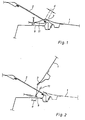
- the aerodynamic shape optimization of a passenger car can result in the tailgate 1 overlapping the lower frame part of the window 2 with its flap edge 3 adjacent to it due to the flatly inclined installation position of the tailgate 2.
- the flap 1 is articulated on the motor vehicle via fastening arms 11 which are drawn far around the rear window 2, so that its pivot axis 9 lies below the window.
- the pivot axis 9 is shifted backwards by a predetermined amount a so that the front flap edge 3 of the swung-open tailgate 1 does not abut the pane of the window 2 and therefore neither the pane nor the flap edge 3 is damaged can be.
- the flap 1 is installed in front of the window 2 window. Because of the overlap d of the lower window frame part by the front flap edge 3, however, the pane of the window 2 cannot be installed either with the flap 1 closed according to FIG. 1 or with the flap 1 open according to FIG. 2. Nevertheless, in the motor vehicle shown, the installation of the window pane 2 is possible without dismantling the flap 1 for the pane assembly and its reinstallation after the pane assembly, because the flap 1 according to FIG. 3 needs an additional dimension b from the pivoted-open position if necessary can be moved to the rear and swiveled away.
- the front edge of the front flap edge 3 is offset to the rear by a sufficiently large distance c from the lower frame part of the window, as a result of which the pane 2 can be installed without any risk of damage to itself or the flap edge 3. Accordingly, the pane of the window 2 can be replaced by a new pane without having to remove the flap 1.
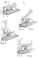
- FIG. 4 shows an embodiment of a flap hinge with which the displacement options for the flap 1 described with reference to FIGS. 1 to 3 are realized.
- the pivot bearing plate 4 on which the flap 1 is pivoted about the pivot axis 9, is in egg ner guide rail 5 guided in the longitudinal direction of the motor vehicle.
- the swivel bearing plate 4 designed as an angle plate engages in an angular guide gap 12 of the guide rail.
- a vertically standing, downwardly projecting gear segment 6 is formed such that the center point of its tooth circle lies in the pivot axis 9 of the flap 1.
- the gear segment 6 engages from above in a pinion 7, which is rotatably mounted in the pivot bearing plate 4 below the pivot axis 9 and offset against it to the rear.
- the pinion 7 also engages in a lower rack 8 which is formed on the guide rail 5.
- an upper rack 10 is formed on the guide rail 5, which is arranged offset to the rear relative to the lower rack 8.
- FIGS. 9 and 10 corresponds to that from FIGS. 5 to 8 with the exception that the rear upper rack 10 is missing. Therefore, if the pinion 7 in the position according to FIG. 9 has run off the lower rack 8, the fastening arm 13 of the flap can be pivoted with the latter, the pinion 7 running freely, and in doing so, until it starts up against the rear stop 15 of the guide rail be pulled at the rear, whereby the flap is displaced by the additional dimension b.
- the position of the hinge parts in this position of the pivoted and pulled back position is shown in Fig. 10.
- the guide rail 5 is fixed outside the access opening of the usable space on the bottom of the lateral water drainage channel 14.
- the gear segment 6 and the racks 8 and 10 are laterally offset from one another, so that the height of the pivot axis 9 above the lower rack 8 is smaller than the radius of the toothed circle of the gear segment 6 can be without this colliding with the lower rack 8.
- the gear segment 6 and the swivel plate 4 are arranged perpendicular to the longitudinal direction of the vehicle at such a distance that the lower rack 8 and the upper rack 10 can protrude between the gear segment 6 and the swivel bearing plate 4.
Landscapes
- Engineering & Computer Science (AREA)
- Mechanical Engineering (AREA)
- Power-Operated Mechanisms For Wings (AREA)
Claims (4)
Applications Claiming Priority (2)
| Application Number | Priority Date | Filing Date | Title |
|---|---|---|---|
| DE19843445812 DE3445812A1 (de) | 1984-12-15 | 1984-12-15 | Personenkraftwagen |
| DE3445812 | 1984-12-15 |
Publications (3)
| Publication Number | Publication Date |
|---|---|
| EP0185246A2 EP0185246A2 (fr) | 1986-06-25 |
| EP0185246A3 EP0185246A3 (en) | 1987-01-07 |
| EP0185246B1 true EP0185246B1 (fr) | 1989-03-22 |
Family
ID=6252875
Family Applications (1)
| Application Number | Title | Priority Date | Filing Date |
|---|---|---|---|
| EP85115362A Expired EP0185246B1 (fr) | 1984-12-15 | 1985-12-04 | Charnière pour capot avant ou arrière d'une automobile |
Country Status (2)
| Country | Link |
|---|---|
| EP (1) | EP0185246B1 (fr) |
| DE (2) | DE3445812A1 (fr) |
Cited By (1)
| Publication number | Priority date | Publication date | Assignee | Title |
|---|---|---|---|---|
| US7283897B2 (en) * | 2002-05-31 | 2007-10-16 | Quantum Engineering, Inc. | Method and system for compensating for wheel wear on a train |
Families Citing this family (4)
| Publication number | Priority date | Publication date | Assignee | Title |
|---|---|---|---|---|
| DE3743502A1 (de) * | 1987-12-22 | 1989-07-06 | Bayerische Motoren Werke Ag | Lagerung eines klappbaren deckels eines kraftfahrzeugs, insbesondere eines verdeckkastendeckels |
| DE3815450C2 (de) * | 1988-05-06 | 1995-03-09 | Grass Alfred Metallwaren | Weitwinkel-Scharnier mit Zahnrad-Getriebe |
| DE19944436A1 (de) * | 1999-09-16 | 2001-03-22 | Volkswagen Ag | Kraftfahrzeug-Vorderwagen |
| DE102010007898A1 (de) | 2010-02-13 | 2011-08-18 | Volkswagen AG, 38440 | Vorderwagen eines Fahrzeugs |
Family Cites Families (5)
| Publication number | Priority date | Publication date | Assignee | Title |
|---|---|---|---|---|
| DE1216134B (de) * | 1961-10-10 | 1966-05-05 | Auto Union Gmbh | Gelenk fuer Klappen, Deckel od. dgl., insbesondere an Kraftfahrzeugen |
| DE2651410C2 (de) * | 1976-11-11 | 1985-11-14 | Daimler-Benz Ag, 7000 Stuttgart | Scharnier für Hauben, Klappen oder Türen von Kraftwagen |
| IT7722574U1 (it) * | 1977-10-25 | 1979-04-25 | Alfa Romeo Spa | Dispositivo di imperniamento del coperchio di un vano di una autovettura |
| DE3315129A1 (de) * | 1983-04-27 | 1984-10-31 | Bayerische Motoren Werke AG, 8000 München | Scharnier fuer klappen an kraftfahrzeugen |
| EP0141145B1 (fr) * | 1983-09-08 | 1987-12-09 | Bayerische Motoren Werke Aktiengesellschaft, Patentabteilung AJ-3 | Dispositif d'articulation pour une partie de carrosserie d'un véhicule automobile, en particulier pour un capot de coffre à bagages d'une carrosserie de voiture de tourisme |
-
1984
- 1984-12-15 DE DE19843445812 patent/DE3445812A1/de not_active Withdrawn
-
1985
- 1985-12-04 EP EP85115362A patent/EP0185246B1/fr not_active Expired
- 1985-12-04 DE DE8585115362T patent/DE3569008D1/de not_active Expired
Cited By (1)
| Publication number | Priority date | Publication date | Assignee | Title |
|---|---|---|---|---|
| US7283897B2 (en) * | 2002-05-31 | 2007-10-16 | Quantum Engineering, Inc. | Method and system for compensating for wheel wear on a train |
Also Published As
| Publication number | Publication date |
|---|---|
| EP0185246A2 (fr) | 1986-06-25 |
| DE3445812A1 (de) | 1986-06-19 |
| EP0185246A3 (en) | 1987-01-07 |
| DE3569008D1 (en) | 1989-04-27 |
Similar Documents
| Publication | Publication Date | Title |
|---|---|---|
| DE3137191A1 (de) | Windabweisvorrichtung an einem kraftfahrzeugdach | |
| DE2153743B2 (de) | Luftdüse für eine Belüftungsanlage | |
| DE3026082C2 (de) | Trittstufe für Kraftfahrzeuge | |
| DE29905681U1 (de) | Schwenkschiebetür für Fahrzeuge, insbesondere Fahrzeuge des öffentlichen Personennahverkehrs | |
| DE2936051C2 (de) | Hebevorrichtung für ein Kraftfahrzeug-Schiebedach | |
| DE2800909C3 (de) | Schlitten mit Schwenkhebel für ein Fahrzeugschiebedach | |
| DE2013277C3 (de) | Fahrzeugaufbau, insbesondere für Kraftfahrzeuge, mit einer Heckklappe | |
| DE3247946C2 (fr) | ||
| EP0185246B1 (fr) | Charnière pour capot avant ou arrière d'une automobile | |
| DE2405881C2 (de) | Fensterheber für ein vertikal unterteiltes Türfenster von Kraftfahrzeugen | |
| EP0185993B1 (fr) | Toit ouvrant pour véhicules automobiles | |
| DE2507893B2 (de) | Fensterheber für vertikal unterteilte Kraftfahrzeugschiebefenster | |
| DE4101288C2 (fr) | ||
| EP0551840B1 (fr) | Toit coulissant pour véhicule automobile | |
| EP1581712B1 (fr) | Unite d'armature pour fenetre ou porte | |
| DE10222998B4 (de) | Rückwandtür mit Türsicherungselementen für ein Lastfahrzeug | |
| WO1990001099A1 (fr) | Porte pliante a plusieurs vantaux | |
| DE2223208A1 (de) | Abdeckhaubenabstuetzung | |
| DE4126716C2 (de) | Drehführung für eine Außenschwingtür eines Fahrzeuges | |
| EP0551839A1 (fr) | Toit ouvrant pour voiture automobile coulissant au-dessus du toit | |
| DE2249718C3 (de) | Schiebedach für Kraftfahrzeuge | |
| DE3045363C2 (fr) | ||
| DE3133379C2 (fr) | ||
| DE20006997U1 (de) | Schiebetür | |
| CH623521A5 (en) | Superstructure for vehicles having at least one displaceable door |
Legal Events
| Date | Code | Title | Description |
|---|---|---|---|
| PUAI | Public reference made under article 153(3) epc to a published international application that has entered the european phase |
Free format text: ORIGINAL CODE: 0009012 |
|
| AK | Designated contracting states |
Kind code of ref document: A2 Designated state(s): DE FR GB IT |
|
| PUAL | Search report despatched |
Free format text: ORIGINAL CODE: 0009013 |
|
| AK | Designated contracting states |
Kind code of ref document: A3 Designated state(s): DE FR GB IT |
|
| 17P | Request for examination filed |
Effective date: 19870120 |
|
| 17Q | First examination report despatched |
Effective date: 19880112 |
|
| GRAA | (expected) grant |
Free format text: ORIGINAL CODE: 0009210 |
|
| AK | Designated contracting states |
Kind code of ref document: B1 Designated state(s): DE FR GB IT |
|
| REF | Corresponds to: |
Ref document number: 3569008 Country of ref document: DE Date of ref document: 19890427 |
|
| ET | Fr: translation filed | ||
| ITF | It: translation for a ep patent filed | ||
| GBT | Gb: translation of ep patent filed (gb section 77(6)(a)/1977) | ||
| PLBE | No opposition filed within time limit |
Free format text: ORIGINAL CODE: 0009261 |
|
| STAA | Information on the status of an ep patent application or granted ep patent |
Free format text: STATUS: NO OPPOSITION FILED WITHIN TIME LIMIT |
|
| 26N | No opposition filed | ||
| ITTA | It: last paid annual fee | ||
| PGFP | Annual fee paid to national office [announced via postgrant information from national office to epo] |
Ref country code: GB Payment date: 19911204 Year of fee payment: 7 |
|
| PGFP | Annual fee paid to national office [announced via postgrant information from national office to epo] |
Ref country code: FR Payment date: 19911230 Year of fee payment: 7 |
|
| PG25 | Lapsed in a contracting state [announced via postgrant information from national office to epo] |
Ref country code: GB Effective date: 19921204 |
|
| GBPC | Gb: european patent ceased through non-payment of renewal fee |
Effective date: 19921204 |
|
| PG25 | Lapsed in a contracting state [announced via postgrant information from national office to epo] |
Ref country code: FR Effective date: 19930831 |
|
| REG | Reference to a national code |
Ref country code: FR Ref legal event code: ST |
|
| PGFP | Annual fee paid to national office [announced via postgrant information from national office to epo] |
Ref country code: DE Payment date: 19931203 Year of fee payment: 9 |
|
| PG25 | Lapsed in a contracting state [announced via postgrant information from national office to epo] |
Ref country code: DE Effective date: 19950901 |