EP0185251B1 - Geschosszünder - Google Patents
Geschosszünder Download PDFInfo
- Publication number
- EP0185251B1 EP0185251B1 EP85115388A EP85115388A EP0185251B1 EP 0185251 B1 EP0185251 B1 EP 0185251B1 EP 85115388 A EP85115388 A EP 85115388A EP 85115388 A EP85115388 A EP 85115388A EP 0185251 B1 EP0185251 B1 EP 0185251B1
- Authority
- EP
- European Patent Office
- Prior art keywords
- piston
- cylinder
- projectile
- centrifugal force
- medium
- Prior art date
- Legal status (The legal status is an assumption and is not a legal conclusion. Google has not performed a legal analysis and makes no representation as to the accuracy of the status listed.)
- Expired
Links
- 238000007789 sealing Methods 0.000 claims description 7
- 239000012530 fluid Substances 0.000 claims 2
- 230000000903 blocking effect Effects 0.000 claims 1
- 239000007788 liquid Substances 0.000 description 9
- 230000006835 compression Effects 0.000 description 5
- 238000007906 compression Methods 0.000 description 5
- 238000000034 method Methods 0.000 description 2
- 230000035939 shock Effects 0.000 description 2
- 230000003111 delayed effect Effects 0.000 description 1
- 238000006073 displacement reaction Methods 0.000 description 1
- 230000000694 effects Effects 0.000 description 1
Images
Classifications
-
- F—MECHANICAL ENGINEERING; LIGHTING; HEATING; WEAPONS; BLASTING
- F42—AMMUNITION; BLASTING
- F42C—AMMUNITION FUZES; ARMING OR SAFETY MEANS THEREFOR
- F42C15/00—Arming-means in fuzes; Safety means for preventing premature detonation of fuzes or charges
- F42C15/28—Arming-means in fuzes; Safety means for preventing premature detonation of fuzes or charges operated by flow of fluent material, e.g. shot, fluids
- F42C15/285—Arming-means in fuzes; Safety means for preventing premature detonation of fuzes or charges operated by flow of fluent material, e.g. shot, fluids stored within the fuze housing
-
- F—MECHANICAL ENGINEERING; LIGHTING; HEATING; WEAPONS; BLASTING
- F42—AMMUNITION; BLASTING
- F42C—AMMUNITION FUZES; ARMING OR SAFETY MEANS THEREFOR
- F42C15/00—Arming-means in fuzes; Safety means for preventing premature detonation of fuzes or charges
- F42C15/20—Arming-means in fuzes; Safety means for preventing premature detonation of fuzes or charges wherein a securing-pin or latch is removed to arm the fuze, e.g. removed from the firing-pin
- F42C15/22—Arming-means in fuzes; Safety means for preventing premature detonation of fuzes or charges wherein a securing-pin or latch is removed to arm the fuze, e.g. removed from the firing-pin using centrifugal force
Definitions
- the invention relates to a projectile detonator with a securing element designed as a piston, which is guided in a cylinder provided on the igniter body and engages by means of spring force in the securing with a locking piece in a recess in the igniter carrier and this under centrifugal force and according to the flow velocity of a medium through one against the Piston cross-section releases smaller orifice.
- a securing element designed as a piston
- a projectile detonator with a securing element which releases an igniter carrier under the influence of centrifugal force.
- the known projectile detonator discloses a cylinder which is introduced into a recess on the detonator body as an additional component and in which there is air as a flow medium in addition to a compression spring which can escape through a cover on the bottom side.
- the air can also escape through the gap between the piston and the cylinder wall because the projectile detonator lacks appropriate seals. Therefore, the necessary reproducibility of the piston movement within a constant period of time does not appear to be guaranteed.
- FR-E-68 773 discloses an igniter with a safety device which consists of two pistons, each of which moves radially outwards when centrifugal force is applied and thereby press a liquid or gas out of corresponding chambers through a small opening in a screw plug. Only when the pistons have moved outwards a certain way are holes for the piercing needle cleared so that the ignition can finally take place.
- this object is achieved in that the cylinder is integrally formed on the igniter body and absorbs a liquid as the flow medium, and that the piston as a securing element is sealed off from the cylinder by means of axially and radially acting sealing rings and has a passage opening to the cylinder, and finally that the piston centrifugal force pushes the liquid filling the cylinder through the passage opening from one side of the piston to the other side of the piston.
- the piston in the cylinder is moved outwards. This movement is gradual as the piston is braked. It can only move in the time unit by a distance that corresponds to the volume of the medium pressed through the passage opening.
- the securing element thus only releases the igniter carrier after a delay. Among other things, this depends on the cross-section of the flow opening and the viscosity of the medium.
- a liquid is preferably used as the medium.
- Shocks acting on the projectile body are dampened by the medium in such a way that the igniter carrier is not released by shocks.
- the sealing rings used and the passage opening from the piston to the cylinder with a defined diameter and in relation to the piston cross-section allows a targeted and predeterminable sequence of movements of the piston within the cylinder.
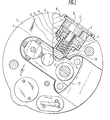
- a cylinder 2 is formed in an ignition body 1.
- a piston 3 is mounted in this.
- a locking piece 4 is formed on the piston 3. In this sits a compression spring 5, which is supported on a sealing washer 6, which closes the cylinder 2. A pin 7 for guiding the compression spring 5 is provided on the sealing disk 6.
- the piston 3 is sealed by means of a sealing ring 8 in the cylinder 2.
- a sealing ring 9 seals the locking piece 4.
- the piston 3 has a passage opening 10, the cross section of which is considerably smaller than the cross section of the piston 3.
- the cylinder 2 is filled with a liquid 11.
- An igniter carrier 12 is mounted in the igniter body 1 and has a recess 13 into which the locking piece 4 engages to ensure it.
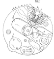
- the projectile detonator is subjected to a swirl to ensure that the piston 3 moves outwards against the force of the compression spring 5 under the action of centrifugal force. Its movement is delayed by the liquid 11. It can only move in the time unit by a distance which corresponds to the flow rate of the liquid 11 passing through the passage opening 10 in the time unit.
- the locking piece 4 of the piston 3 has left the recess 13.
- the igniter carrier 12 then moves into the focus under the action of the centrifugal force in which the ignition can then take place. Adequate safety of the front pipe is guaranteed by the braked piston movement.
Landscapes
- Engineering & Computer Science (AREA)
- General Engineering & Computer Science (AREA)
- Air Bags (AREA)
- Fuses (AREA)
- Switches Operated By Changes In Physical Conditions (AREA)
Description
- Die Erfindung betrifft einen Geschosszünder mit einem als Kolben ausgebildeten Sicherungselement, der in einem am Zünderkörper vorgesehenen Zylinder geführt ist und mittels Federkraft in der Sicherstellung mit einem Sperrstück in eine Ausnehmung am Anzündmittelträger greift und diesen unter Fliehkrafteinwirkung und entsprechend der Strömungsgeschwindigkeit eines Mediums durch eine gegenüber dem Kolbenquerschnitt kleinere Blende freigibt.
- Aus der US-A-3 356 028 ist ein Geschosszünder mit einem Sicherungselement bekannt, das unter Fliehkrafteinwirkung einen Anzündmittelträger freigibt. Dabei offenbart der bekannte Geschosszünder einen in eine Ausnehmung am Zünderkörper als zusätzliches Bauteil eingebrachten Zylinder, in welchem sich neben einer Druckfeder als Strömungsmedium Luft befindet, die bodenseitig durch eine Blende entweichen kann. Die Luft kann jedoch auch durch den Spalt zwischen dem Kolben und der Zylinderwand entweichen, weil es dem Geschosszünder an entsprechenden Abdichtungen mangelt. Deshalb erscheint auch die notwendige Reproduzierbarkeit der Kolbenbewegung innerhalb einer immer gleichen Zeitspanne nicht gewährleistet zu sein.
- Die FR-E-68 773 offenbart einen Zünder mit einer Sicherungseinrichtung, die aus zwei Kolben besteht, die bei Fliehkrafteinwirkung jeweils radial nach aussen wandern und dabei eine Flüssigkeit oder ein Gas aus entsprechenden Kammern durch eine kleine Öffnung in einer Verschlussschraube herauspressen. Erst wenn die Kolben einen bestimmten Weg nach aussen gewandert sind, werden Bohrungen für die Anstechnadel frei, so dass schliesslich die Zündung erfolgen kann.
- Schliesslich ist noch ein Sicherungsmechanismus für einen Bombenzünder durch die US-A-3 263 035 bekannt, bei welchem eine Flüssigkeit von einem Ringzylinderraum durch eine schmale radiale Öffnung in den Hohlraum des Kolbens gedrückt wird. Dieser Vorgang erfolgt bei einer Axialkraft durch den Kolben so lange, bis mehrere kreisförmig angeordnete Kugeln in radialen Ausnehmungen des Kolbens einrasten.
- Es ist Aufgabe der Erfindung, einen Geschosszünder der eingangs genannten Art vorzuschlagen, bei dem das Sicherungselement unempfindlich gegen Stösse ist und durch einen gezielten und vorherbestimmten Bewegungsablauf eine Vorrohrsicherheit gewährleistet.
- Erfindungsgemäss wird diese Aufgabe dadurch gelöst, dass der Zylinder am Zünderkörper angeformt ist und als Strömungsmedium eine Flüssigkeit aufnimmt, und dass der Kolben als Sicherungselement durch axial und radial wirkende Dichtringe gegenüber dem Zylinder abgedichtet ist und eine Durchtrittsöffnung zum Zylinder aufweist, und dass schliesslich der Kolben die den Zylinder ausfüllende Flüssigkeit unter Fliehkrafteinwirkung durch die Durchtrittsöffnung von der einen Kolbenseite zur anderen Kolbenseite drückt.
- Rotiert das Geschoss infolge seines Dralls, dann wird der Kolben in dem Zylinder nach aussen bewegt. Diese Bewegung geht allmählich vor sich, da der Kolben gebremst ist. Er kann sich in der Zeiteinheit nur um eine Strecke verschieben, die dem Volumen des durch die Durchtrittsöffnung gepressten Mediums entspricht. Das Sicherungselement gibt damit den Anzündmittelträger erst nach einer Verzögerungszeit frei. Diese ist unter anderem abhängig vom Querschnitt der Durchflussöffnung und der Viskosität des Mediums. Vorzugsweise wird als Medium eine Flüssigkeit verwendet.
- Auf den Geschosskörper wirkende Stösse werden von dem Medium so gedämpft, dass der Anzündmittelträger durch Stösse nicht freigegeben wird.
- Die eingesetzten Dichtringe und die vom Kolben zum Zylinder geführte Durchtrittsöffnung von definiertem und im Verhältnis zum Kolbenquerschnitt stehenden Durchmesser erlaubt einen gezielten und zeitlich vorherbestimmbaren Bewegungsablauf des Kolbens innerhalb des Zylinders.
- In der Zeichnung ist ein Beispiel der Erfindung dargestellt. Es zeigen:
- Figur 1 einen Geschosszünder im Querschnitt in Sicherstellung und
- Figur 2 den Geschosszünder in Scharfstellung.
- In einem Zündkörper 1 ist ein Zylinder 2 ausgebildet. In diesem ist ein Kolben 3 gelagert.
- Am Kolben 3 ist ein Sperrstück 4 ausgebildet. In diesem sitzt eine Druckfeder 5, welche sich an einer Dichtscheibe 6 abstützt, die den Zylinder 2 abschliesst. An der Dichtscheibe 6 ist ein Zapfen 7 zur Führung der Druckfeder 5 vorgesehen.
- Der Kolben 3 ist mittels eines Dichtringes 8 im Zylinder 2 abgedichtet. Ein Dichtring 9 dichtet das Sperrstück 4 ab. der Kolben 3 weist eine Durchtrittsöffnung 10 auf, deren Querschnitt wesentlich kleiner ist als der Querschnitt des Kolbens 3. Der Zylinder 2 ist mit einer Flüssigkeit 11 gefüllt.
- In dem Zünderkörper 1 ist ein Anzündmittelträger 12 gelagert, der eine Ausnehmung 13 aufweist, in welche in Sicherstellung das Sperrstück 4 eingreift.
- Die Funktionsweise des beschriebenen Geschosszünders ist etwa folgende:
- Wird aus der Sicherstellung der Geschosszünder einem Drall unterworfen, dann wandert unter Fliehkraftwirkung der Kolben 3 gegen die Kraft der Druckfeder 5 nach aussen. Seine Bewegung ist durch die Flüssigkeit 11 verzögert. Er kann sich in der Zeiteinheit nur um eine Strecke bewegen, die der in der Zeiteinheit durch die Durchtrittsöffnung 10 hindurchtretenden Durchflussmenge der Flüssigkeit 11 entspricht.
- Nach einer gewissen Verzögerungszeit, beispielsweise etwa 20 bis 30 ms, hat das Sperrstück 4 des Kolbens 3 die Ausnehmung 13 verlassen. Unter der Wirkung der Fliehkraft bewegt sich der Anzündmittelträger 12 dann in die Scharfstellung, in der dann die Zündung erfolgen kann. Durch die gebremste Kolbenbewegung ist eine hinreichende Vorrohrsicherheit gewährleistet.
- Auf den Zünderkörper 1 wirkende kurzzeitige Stösse oder Schläge werden in ihrer Auswirkung auf den Kolben 3 bzw. das Sperrstück 4 unterdrückt, da die Flüssigkeit 11 die Kolbenbewegung dämpft. Kleine Verschiebungen des Sperrstückes 4 werden durch die Druckfeder 5 rückgängig gemacht.
Claims (1)
- Geschosszünder mit einem als Kolben (3) ausgebildeten Sicherungselement, der in einem am Zündkörper (1) vorgesehenen Zylinder (2) geführt ist und mittels Federkraft in der Sicherstellung mit einem Sperrstück (4) in eine Ausnehmung (13) am Anzündmittelträger (12) greift und diesen unter Fliehkrafteinwirkung und entsprechend der Strömungsgeschwindigkeit eines Mediums (11) durch eine gegenüber dem Kolbenquerschnitt kleinere Blende freigibt, dadurch gekennzeichnet, dass der Zylinder (2) am Zünderkörper (1) angeformt ist und als Strömungsmedium eine Flüssigkeit (11) aufnimmt, dass der Kolben (3) als Sicherungselement durch axial und radial wirkende Dichtringe (8, 9) gegenüber dem Zylinder (2) abgedichtet ist und eine Durchtrittsöffnung (10) zum Zylinder (2) aufweist, und dass der Kolben (3) die den Zylinder (2) ausfüllende Flüssigkeit (11) unter Fliehkrafteinwirkung durch die Durchtrittsöffnung (10) von der einen Kolbenseite zur anderen Kolbenseite drückt.
Applications Claiming Priority (2)
| Application Number | Priority Date | Filing Date | Title |
|---|---|---|---|
| DE3446098 | 1984-12-18 | ||
| DE19843446098 DE3446098A1 (de) | 1984-12-18 | 1984-12-18 | Geschosszuender |
Publications (2)
| Publication Number | Publication Date |
|---|---|
| EP0185251A1 EP0185251A1 (de) | 1986-06-25 |
| EP0185251B1 true EP0185251B1 (de) | 1988-12-28 |
Family
ID=6253061
Family Applications (1)
| Application Number | Title | Priority Date | Filing Date |
|---|---|---|---|
| EP85115388A Expired EP0185251B1 (de) | 1984-12-18 | 1985-12-04 | Geschosszünder |
Country Status (3)
| Country | Link |
|---|---|
| US (1) | US4653402A (de) |
| EP (1) | EP0185251B1 (de) |
| DE (2) | DE3446098A1 (de) |
Families Citing this family (8)
| Publication number | Priority date | Publication date | Assignee | Title |
|---|---|---|---|---|
| US4938138A (en) * | 1989-08-07 | 1990-07-03 | Honeywell Inc. | Safing and arming mechanism with creep ribbon arming delay |
| FR2815659A1 (fr) * | 2000-10-19 | 2002-04-26 | Atmostat Etudes Et Rech S | Dispositif a securite passive levee par une acceleration |
| US6564716B1 (en) | 2001-12-05 | 2003-05-20 | Kdi Precision Products, Inc. | Fuzes having centrifugal arming lock for a munition |
| KR100616470B1 (ko) | 2004-12-29 | 2006-08-29 | 국방과학연구소 | 슬라이더 차단식 소형 안전장전장치 |
| US9470498B1 (en) * | 2014-09-05 | 2016-10-18 | The United States Of America As Represented By The Secretary Of The Army | High pressure isolated latching safety switch device |
| CN113091537B (zh) * | 2021-04-09 | 2024-02-13 | 南京理工大学 | 实现爆炸物处理和不敏感特性的旋转弹引信传爆隔断机构 |
| DE102022106883A1 (de) * | 2022-03-23 | 2023-09-28 | Rheinmetall Air Defence Ag | Sicherungseinheit für einen Zünder, Verwendung der Sicherungseinheit und Verfahren zur Aktivierung eines Zünders mit dieser Sicherungseinheit |
| US12272844B1 (en) | 2023-05-10 | 2025-04-08 | The United States Of America As Represented By The Secretary Of The Army | Pressure activated battery system |
Citations (1)
| Publication number | Priority date | Publication date | Assignee | Title |
|---|---|---|---|---|
| FR68773E (fr) * | 1955-08-04 | 1958-06-10 | Perfectionnement aux fusées à sécurité de bouche |
Family Cites Families (11)
| Publication number | Priority date | Publication date | Assignee | Title |
|---|---|---|---|---|
| NL92254C (de) * | 1951-03-20 | |||
| US2994271A (en) * | 1954-04-22 | 1961-08-01 | Silver Meyer | Fuze arming device |
| US2977883A (en) * | 1955-08-09 | 1961-04-04 | Czajkowski Norman | Detent release mechanism |
| NL225272A (de) * | 1957-02-26 | |||
| FR1256033A (fr) * | 1960-02-02 | 1961-03-17 | Fusée à sécurité de bouche | |
| US3263035A (en) * | 1964-08-31 | 1966-07-26 | Robert H Semenoff | Retard sensor for retarded bombs |
| US3356028A (en) * | 1966-06-28 | 1967-12-05 | Robert W Heinemann | Safety device for an explosive fuze |
| GB1173495A (en) * | 1967-03-06 | 1969-12-10 | Instr Res Lab Ltd | Release Mechanism |
| US3425354A (en) * | 1967-10-30 | 1969-02-04 | Honeywell Inc | Centrifugally armed fuze |
| US3608493A (en) * | 1969-04-10 | 1971-09-28 | Honeywell Inc | Fuse apparatus |
| US3919941A (en) * | 1973-09-25 | 1975-11-18 | David S Breed | Liquid timing device |
-
1984
- 1984-12-18 DE DE19843446098 patent/DE3446098A1/de not_active Ceased
-
1985
- 1985-11-25 US US06/802,017 patent/US4653402A/en not_active Expired - Fee Related
- 1985-12-04 DE DE8585115388T patent/DE3567096D1/de not_active Expired
- 1985-12-04 EP EP85115388A patent/EP0185251B1/de not_active Expired
Patent Citations (1)
| Publication number | Priority date | Publication date | Assignee | Title |
|---|---|---|---|---|
| FR68773E (fr) * | 1955-08-04 | 1958-06-10 | Perfectionnement aux fusées à sécurité de bouche |
Also Published As
| Publication number | Publication date |
|---|---|
| US4653402A (en) | 1987-03-31 |
| DE3567096D1 (en) | 1989-02-02 |
| EP0185251A1 (de) | 1986-06-25 |
| DE3446098A1 (de) | 1986-06-26 |
Similar Documents
| Publication | Publication Date | Title |
|---|---|---|
| EP0185251B1 (de) | Geschosszünder | |
| DE2550093C3 (de) | Beharrungszünder für Drallgeschosse mit Selbstzerlegereinrichtung | |
| DE3149346C2 (de) | ||
| DE2838381C2 (de) | Sicherheitsvorrichtung für Zündvorrichtungen | |
| DE1148162B (de) | Zuender fuer Drallgeschosse | |
| DE1018757B (de) | Aufschlagzuender fuer Geschosse, insbesondere Wurfminen | |
| DE2548863C3 (de) | Unterwasserzündvorrichtung | |
| DE3133364C2 (de) | ||
| AT130321B (de) | Geschoßzünder für Aufschlag- und Trägheitswirkung. | |
| DE3119369A1 (de) | Beharrungszuender fuer drallgeschosse mit selbstzerlegereinrichtung | |
| DE2039400A1 (de) | Geschosszuender | |
| DE3740966A1 (de) | Pyrotechnischer zuender fuer geschosse, raketen, bomblets und minen | |
| DE1028468B (de) | Zerlegerzuender | |
| CH665021A5 (de) | Drallgeschosszuender. | |
| DE2918039A1 (de) | Mechanischer aufschlagzerlegerzuender fuer drallstabilisierte geschosse | |
| DE2735575A1 (de) | Aufschlagzuender fuer drallgeschosse | |
| DE69605332T2 (de) | Vorrichtung zum Sichern und Schärfen des Zünders eines Geschosses | |
| DE1041394B (de) | Landminen-Druckzuender | |
| AT229194B (de) | Zünder für rotierende Geschosse | |
| DE1946991A1 (de) | Hohlladung | |
| DE2727856C2 (de) | Regensicherungsvorrichtung für einen Spitzenaufschlagzünder für Projektile | |
| AT206330B (de) | Drallstabilisiertes Hohlladungsgeschoß | |
| AT243651B (de) | Sicherheitseinrichtung für Geschoßzünder | |
| DE8436998U1 (de) | Geschoßzünder | |
| DE713331C (de) | Sicherung fuer Drallgeschosszuender |
Legal Events
| Date | Code | Title | Description |
|---|---|---|---|
| PUAI | Public reference made under article 153(3) epc to a published international application that has entered the european phase |
Free format text: ORIGINAL CODE: 0009012 |
|
| AK | Designated contracting states |
Kind code of ref document: A1 Designated state(s): CH DE FR GB IT LI SE |
|
| 17P | Request for examination filed |
Effective date: 19860604 |
|
| 17Q | First examination report despatched |
Effective date: 19870511 |
|
| GRAA | (expected) grant |
Free format text: ORIGINAL CODE: 0009210 |
|
| AK | Designated contracting states |
Kind code of ref document: B1 Designated state(s): CH DE FR GB IT LI SE |
|
| REF | Corresponds to: |
Ref document number: 3567096 Country of ref document: DE Date of ref document: 19890202 |
|
| ITF | It: translation for a ep patent filed | ||
| GBT | Gb: translation of ep patent filed (gb section 77(6)(a)/1977) | ||
| ET | Fr: translation filed | ||
| PLBE | No opposition filed within time limit |
Free format text: ORIGINAL CODE: 0009261 |
|
| STAA | Information on the status of an ep patent application or granted ep patent |
Free format text: STATUS: NO OPPOSITION FILED WITHIN TIME LIMIT |
|
| 26N | No opposition filed | ||
| ITTA | It: last paid annual fee | ||
| PGFP | Annual fee paid to national office [announced via postgrant information from national office to epo] |
Ref country code: CH Payment date: 19931111 Year of fee payment: 9 |
|
| PGFP | Annual fee paid to national office [announced via postgrant information from national office to epo] |
Ref country code: FR Payment date: 19931129 Year of fee payment: 9 |
|
| PGFP | Annual fee paid to national office [announced via postgrant information from national office to epo] |
Ref country code: GB Payment date: 19931201 Year of fee payment: 9 |
|
| PGFP | Annual fee paid to national office [announced via postgrant information from national office to epo] |
Ref country code: SE Payment date: 19931229 Year of fee payment: 9 |
|
| PG25 | Lapsed in a contracting state [announced via postgrant information from national office to epo] |
Ref country code: GB Effective date: 19941204 |
|
| PG25 | Lapsed in a contracting state [announced via postgrant information from national office to epo] |
Ref country code: SE Effective date: 19941205 |
|
| PG25 | Lapsed in a contracting state [announced via postgrant information from national office to epo] |
Ref country code: LI Effective date: 19941231 Ref country code: CH Effective date: 19941231 |
|
| EAL | Se: european patent in force in sweden |
Ref document number: 85115388.2 |
|
| PGFP | Annual fee paid to national office [announced via postgrant information from national office to epo] |
Ref country code: DE Payment date: 19950218 Year of fee payment: 10 |
|
| GBPC | Gb: european patent ceased through non-payment of renewal fee |
Effective date: 19941204 |
|
| PG25 | Lapsed in a contracting state [announced via postgrant information from national office to epo] |
Ref country code: FR Effective date: 19950831 |
|
| REG | Reference to a national code |
Ref country code: CH Ref legal event code: PL |
|
| EUG | Se: european patent has lapsed |
Ref document number: 85115388.2 |
|
| REG | Reference to a national code |
Ref country code: FR Ref legal event code: ST |
|
| PG25 | Lapsed in a contracting state [announced via postgrant information from national office to epo] |
Ref country code: DE Effective date: 19960903 |