EP0185252A2 - Procédé pour la récupération d'hydrocarbures en C2+ ou C3+ - Google Patents
Procédé pour la récupération d'hydrocarbures en C2+ ou C3+ Download PDFInfo
- Publication number
- EP0185252A2 EP0185252A2 EP85115406A EP85115406A EP0185252A2 EP 0185252 A2 EP0185252 A2 EP 0185252A2 EP 85115406 A EP85115406 A EP 85115406A EP 85115406 A EP85115406 A EP 85115406A EP 0185252 A2 EP0185252 A2 EP 0185252A2
- Authority
- EP
- European Patent Office
- Prior art keywords
- rectification
- gas stream
- fraction
- hydrocarbons
- separated
- Prior art date
- Legal status (The legal status is an assumption and is not a legal conclusion. Google has not performed a legal analysis and makes no representation as to the accuracy of the status listed.)
- Granted
Links
Images



Classifications
-
- F—MECHANICAL ENGINEERING; LIGHTING; HEATING; WEAPONS; BLASTING
- F25—REFRIGERATION OR COOLING; COMBINED HEATING AND REFRIGERATION SYSTEMS; HEAT PUMP SYSTEMS; MANUFACTURE OR STORAGE OF ICE; LIQUEFACTION SOLIDIFICATION OF GASES
- F25J—LIQUEFACTION, SOLIDIFICATION OR SEPARATION OF GASES OR GASEOUS OR LIQUEFIED GASEOUS MIXTURES BY PRESSURE AND COLD TREATMENT OR BY BRINGING THEM INTO THE SUPERCRITICAL STATE
- F25J3/00—Processes or apparatus for separating the constituents of gaseous or liquefied gaseous mixtures involving the use of liquefaction or solidification
- F25J3/02—Processes or apparatus for separating the constituents of gaseous or liquefied gaseous mixtures involving the use of liquefaction or solidification by rectification, i.e. by continuous interchange of heat and material between a vapour stream and a liquid stream
- F25J3/0228—Processes or apparatus for separating the constituents of gaseous or liquefied gaseous mixtures involving the use of liquefaction or solidification by rectification, i.e. by continuous interchange of heat and material between a vapour stream and a liquid stream characterised by the separated product stream
- F25J3/0242—Processes or apparatus for separating the constituents of gaseous or liquefied gaseous mixtures involving the use of liquefaction or solidification by rectification, i.e. by continuous interchange of heat and material between a vapour stream and a liquid stream characterised by the separated product stream separation of CnHm with 3 carbon atoms or more
-
- C—CHEMISTRY; METALLURGY
- C07—ORGANIC CHEMISTRY
- C07C—ACYCLIC OR CARBOCYCLIC COMPOUNDS
- C07C7/00—Purification; Separation; Use of additives
- C07C7/005—Processes comprising at least two steps in series
-
- C—CHEMISTRY; METALLURGY
- C07—ORGANIC CHEMISTRY
- C07C—ACYCLIC OR CARBOCYCLIC COMPOUNDS
- C07C7/00—Purification; Separation; Use of additives
- C07C7/04—Purification; Separation; Use of additives by distillation
-
- C—CHEMISTRY; METALLURGY
- C07—ORGANIC CHEMISTRY
- C07C—ACYCLIC OR CARBOCYCLIC COMPOUNDS
- C07C7/00—Purification; Separation; Use of additives
- C07C7/09—Purification; Separation; Use of additives by fractional condensation
-
- F—MECHANICAL ENGINEERING; LIGHTING; HEATING; WEAPONS; BLASTING
- F25—REFRIGERATION OR COOLING; COMBINED HEATING AND REFRIGERATION SYSTEMS; HEAT PUMP SYSTEMS; MANUFACTURE OR STORAGE OF ICE; LIQUEFACTION SOLIDIFICATION OF GASES
- F25J—LIQUEFACTION, SOLIDIFICATION OR SEPARATION OF GASES OR GASEOUS OR LIQUEFIED GASEOUS MIXTURES BY PRESSURE AND COLD TREATMENT OR BY BRINGING THEM INTO THE SUPERCRITICAL STATE
- F25J3/00—Processes or apparatus for separating the constituents of gaseous or liquefied gaseous mixtures involving the use of liquefaction or solidification
- F25J3/02—Processes or apparatus for separating the constituents of gaseous or liquefied gaseous mixtures involving the use of liquefaction or solidification by rectification, i.e. by continuous interchange of heat and material between a vapour stream and a liquid stream
- F25J3/0204—Processes or apparatus for separating the constituents of gaseous or liquefied gaseous mixtures involving the use of liquefaction or solidification by rectification, i.e. by continuous interchange of heat and material between a vapour stream and a liquid stream characterised by the feed stream
- F25J3/0209—Natural gas or substitute natural gas
-
- F—MECHANICAL ENGINEERING; LIGHTING; HEATING; WEAPONS; BLASTING
- F25—REFRIGERATION OR COOLING; COMBINED HEATING AND REFRIGERATION SYSTEMS; HEAT PUMP SYSTEMS; MANUFACTURE OR STORAGE OF ICE; LIQUEFACTION SOLIDIFICATION OF GASES
- F25J—LIQUEFACTION, SOLIDIFICATION OR SEPARATION OF GASES OR GASEOUS OR LIQUEFIED GASEOUS MIXTURES BY PRESSURE AND COLD TREATMENT OR BY BRINGING THEM INTO THE SUPERCRITICAL STATE
- F25J3/00—Processes or apparatus for separating the constituents of gaseous or liquefied gaseous mixtures involving the use of liquefaction or solidification
- F25J3/02—Processes or apparatus for separating the constituents of gaseous or liquefied gaseous mixtures involving the use of liquefaction or solidification by rectification, i.e. by continuous interchange of heat and material between a vapour stream and a liquid stream
- F25J3/0204—Processes or apparatus for separating the constituents of gaseous or liquefied gaseous mixtures involving the use of liquefaction or solidification by rectification, i.e. by continuous interchange of heat and material between a vapour stream and a liquid stream characterised by the feed stream
- F25J3/0219—Refinery gas, cracking gas, coke oven gas, gaseous mixtures containing aliphatic unsaturated CnHm or gaseous mixtures of undefined nature
-
- F—MECHANICAL ENGINEERING; LIGHTING; HEATING; WEAPONS; BLASTING
- F25—REFRIGERATION OR COOLING; COMBINED HEATING AND REFRIGERATION SYSTEMS; HEAT PUMP SYSTEMS; MANUFACTURE OR STORAGE OF ICE; LIQUEFACTION SOLIDIFICATION OF GASES
- F25J—LIQUEFACTION, SOLIDIFICATION OR SEPARATION OF GASES OR GASEOUS OR LIQUEFIED GASEOUS MIXTURES BY PRESSURE AND COLD TREATMENT OR BY BRINGING THEM INTO THE SUPERCRITICAL STATE
- F25J3/00—Processes or apparatus for separating the constituents of gaseous or liquefied gaseous mixtures involving the use of liquefaction or solidification
- F25J3/02—Processes or apparatus for separating the constituents of gaseous or liquefied gaseous mixtures involving the use of liquefaction or solidification by rectification, i.e. by continuous interchange of heat and material between a vapour stream and a liquid stream
- F25J3/0228—Processes or apparatus for separating the constituents of gaseous or liquefied gaseous mixtures involving the use of liquefaction or solidification by rectification, i.e. by continuous interchange of heat and material between a vapour stream and a liquid stream characterised by the separated product stream
- F25J3/0233—Processes or apparatus for separating the constituents of gaseous or liquefied gaseous mixtures involving the use of liquefaction or solidification by rectification, i.e. by continuous interchange of heat and material between a vapour stream and a liquid stream characterised by the separated product stream separation of CnHm with 1 carbon atom or more
-
- F—MECHANICAL ENGINEERING; LIGHTING; HEATING; WEAPONS; BLASTING
- F25—REFRIGERATION OR COOLING; COMBINED HEATING AND REFRIGERATION SYSTEMS; HEAT PUMP SYSTEMS; MANUFACTURE OR STORAGE OF ICE; LIQUEFACTION SOLIDIFICATION OF GASES
- F25J—LIQUEFACTION, SOLIDIFICATION OR SEPARATION OF GASES OR GASEOUS OR LIQUEFIED GASEOUS MIXTURES BY PRESSURE AND COLD TREATMENT OR BY BRINGING THEM INTO THE SUPERCRITICAL STATE
- F25J3/00—Processes or apparatus for separating the constituents of gaseous or liquefied gaseous mixtures involving the use of liquefaction or solidification
- F25J3/02—Processes or apparatus for separating the constituents of gaseous or liquefied gaseous mixtures involving the use of liquefaction or solidification by rectification, i.e. by continuous interchange of heat and material between a vapour stream and a liquid stream
- F25J3/0228—Processes or apparatus for separating the constituents of gaseous or liquefied gaseous mixtures involving the use of liquefaction or solidification by rectification, i.e. by continuous interchange of heat and material between a vapour stream and a liquid stream characterised by the separated product stream
- F25J3/0238—Processes or apparatus for separating the constituents of gaseous or liquefied gaseous mixtures involving the use of liquefaction or solidification by rectification, i.e. by continuous interchange of heat and material between a vapour stream and a liquid stream characterised by the separated product stream separation of CnHm with 2 carbon atoms or more
-
- F—MECHANICAL ENGINEERING; LIGHTING; HEATING; WEAPONS; BLASTING
- F25—REFRIGERATION OR COOLING; COMBINED HEATING AND REFRIGERATION SYSTEMS; HEAT PUMP SYSTEMS; MANUFACTURE OR STORAGE OF ICE; LIQUEFACTION SOLIDIFICATION OF GASES
- F25J—LIQUEFACTION, SOLIDIFICATION OR SEPARATION OF GASES OR GASEOUS OR LIQUEFIED GASEOUS MIXTURES BY PRESSURE AND COLD TREATMENT OR BY BRINGING THEM INTO THE SUPERCRITICAL STATE
- F25J2200/00—Processes or apparatus using separation by rectification
- F25J2200/02—Processes or apparatus using separation by rectification in a single pressure main column system
-
- F—MECHANICAL ENGINEERING; LIGHTING; HEATING; WEAPONS; BLASTING
- F25—REFRIGERATION OR COOLING; COMBINED HEATING AND REFRIGERATION SYSTEMS; HEAT PUMP SYSTEMS; MANUFACTURE OR STORAGE OF ICE; LIQUEFACTION SOLIDIFICATION OF GASES
- F25J—LIQUEFACTION, SOLIDIFICATION OR SEPARATION OF GASES OR GASEOUS OR LIQUEFIED GASEOUS MIXTURES BY PRESSURE AND COLD TREATMENT OR BY BRINGING THEM INTO THE SUPERCRITICAL STATE
- F25J2200/00—Processes or apparatus using separation by rectification
- F25J2200/74—Refluxing the column with at least a part of the partially condensed overhead gas
-
- F—MECHANICAL ENGINEERING; LIGHTING; HEATING; WEAPONS; BLASTING
- F25—REFRIGERATION OR COOLING; COMBINED HEATING AND REFRIGERATION SYSTEMS; HEAT PUMP SYSTEMS; MANUFACTURE OR STORAGE OF ICE; LIQUEFACTION SOLIDIFICATION OF GASES
- F25J—LIQUEFACTION, SOLIDIFICATION OR SEPARATION OF GASES OR GASEOUS OR LIQUEFIED GASEOUS MIXTURES BY PRESSURE AND COLD TREATMENT OR BY BRINGING THEM INTO THE SUPERCRITICAL STATE
- F25J2200/00—Processes or apparatus using separation by rectification
- F25J2200/90—Details relating to column internals, e.g. structured packing, gas or liquid distribution
-
- F—MECHANICAL ENGINEERING; LIGHTING; HEATING; WEAPONS; BLASTING
- F25—REFRIGERATION OR COOLING; COMBINED HEATING AND REFRIGERATION SYSTEMS; HEAT PUMP SYSTEMS; MANUFACTURE OR STORAGE OF ICE; LIQUEFACTION SOLIDIFICATION OF GASES
- F25J—LIQUEFACTION, SOLIDIFICATION OR SEPARATION OF GASES OR GASEOUS OR LIQUEFIED GASEOUS MIXTURES BY PRESSURE AND COLD TREATMENT OR BY BRINGING THEM INTO THE SUPERCRITICAL STATE
- F25J2205/00—Processes or apparatus using other separation and/or other processing means
- F25J2205/02—Processes or apparatus using other separation and/or other processing means using simple phase separation in a vessel or drum
- F25J2205/04—Processes or apparatus using other separation and/or other processing means using simple phase separation in a vessel or drum in the feed line, i.e. upstream of the fractionation step
-
- F—MECHANICAL ENGINEERING; LIGHTING; HEATING; WEAPONS; BLASTING
- F25—REFRIGERATION OR COOLING; COMBINED HEATING AND REFRIGERATION SYSTEMS; HEAT PUMP SYSTEMS; MANUFACTURE OR STORAGE OF ICE; LIQUEFACTION SOLIDIFICATION OF GASES
- F25J—LIQUEFACTION, SOLIDIFICATION OR SEPARATION OF GASES OR GASEOUS OR LIQUEFIED GASEOUS MIXTURES BY PRESSURE AND COLD TREATMENT OR BY BRINGING THEM INTO THE SUPERCRITICAL STATE
- F25J2210/00—Processes characterised by the type or other details of the feed stream
- F25J2210/12—Refinery or petrochemical off-gas
-
- F—MECHANICAL ENGINEERING; LIGHTING; HEATING; WEAPONS; BLASTING
- F25—REFRIGERATION OR COOLING; COMBINED HEATING AND REFRIGERATION SYSTEMS; HEAT PUMP SYSTEMS; MANUFACTURE OR STORAGE OF ICE; LIQUEFACTION SOLIDIFICATION OF GASES
- F25J—LIQUEFACTION, SOLIDIFICATION OR SEPARATION OF GASES OR GASEOUS OR LIQUEFIED GASEOUS MIXTURES BY PRESSURE AND COLD TREATMENT OR BY BRINGING THEM INTO THE SUPERCRITICAL STATE
- F25J2235/00—Processes or apparatus involving steps for increasing the pressure or for conveying of liquid process streams
- F25J2235/60—Processes or apparatus involving steps for increasing the pressure or for conveying of liquid process streams the fluid being (a mixture of) hydrocarbons
-
- F—MECHANICAL ENGINEERING; LIGHTING; HEATING; WEAPONS; BLASTING
- F25—REFRIGERATION OR COOLING; COMBINED HEATING AND REFRIGERATION SYSTEMS; HEAT PUMP SYSTEMS; MANUFACTURE OR STORAGE OF ICE; LIQUEFACTION SOLIDIFICATION OF GASES
- F25J—LIQUEFACTION, SOLIDIFICATION OR SEPARATION OF GASES OR GASEOUS OR LIQUEFIED GASEOUS MIXTURES BY PRESSURE AND COLD TREATMENT OR BY BRINGING THEM INTO THE SUPERCRITICAL STATE
- F25J2240/00—Processes or apparatus involving steps for expanding of process streams
- F25J2240/40—Expansion without extracting work, i.e. isenthalpic throttling, e.g. JT valve, regulating valve or venturi, or isentropic nozzle, e.g. Laval
-
- F—MECHANICAL ENGINEERING; LIGHTING; HEATING; WEAPONS; BLASTING
- F25—REFRIGERATION OR COOLING; COMBINED HEATING AND REFRIGERATION SYSTEMS; HEAT PUMP SYSTEMS; MANUFACTURE OR STORAGE OF ICE; LIQUEFACTION SOLIDIFICATION OF GASES
- F25J—LIQUEFACTION, SOLIDIFICATION OR SEPARATION OF GASES OR GASEOUS OR LIQUEFIED GASEOUS MIXTURES BY PRESSURE AND COLD TREATMENT OR BY BRINGING THEM INTO THE SUPERCRITICAL STATE
- F25J2270/00—Refrigeration techniques used
- F25J2270/04—Internal refrigeration with work-producing gas expansion loop
-
- F—MECHANICAL ENGINEERING; LIGHTING; HEATING; WEAPONS; BLASTING
- F25—REFRIGERATION OR COOLING; COMBINED HEATING AND REFRIGERATION SYSTEMS; HEAT PUMP SYSTEMS; MANUFACTURE OR STORAGE OF ICE; LIQUEFACTION SOLIDIFICATION OF GASES
- F25J—LIQUEFACTION, SOLIDIFICATION OR SEPARATION OF GASES OR GASEOUS OR LIQUEFIED GASEOUS MIXTURES BY PRESSURE AND COLD TREATMENT OR BY BRINGING THEM INTO THE SUPERCRITICAL STATE
- F25J2270/00—Refrigeration techniques used
- F25J2270/90—External refrigeration, e.g. conventional closed-loop mechanical refrigeration unit using Freon or NH3, unspecified external refrigeration
Definitions
- the invention relates to a process for the separation of C 2+ or C 3+ hydrocarbons from a gas stream containing light hydrocarbons and possibly components which boil more easily than methane, in which the gas stream under increased pressure is cooled, partially condensed and converted into a liquid and a gaseous fraction is separated, and in which the gaseous fraction is expanded to perform work and the liquid fraction is broken down by rectification into a product stream essentially containing C 2+ or C 3+ hydrocarbons and a residual gas stream containing predominantly lower-boiling components.
- Processes of this type are used primarily to separate ethane or propane from natural gases or other gases, for example refinery exhaust gases.
- these processes are suitable for the separation of comparable unsaturated hydrocarbons, for example of ethylene or propylene, provided that these components are present in the gas stream to be separated, which can be the case, for example, with refinery exhaust gases.
- the further ver Processing of refinery exhaust gases has recently become economically interesting as the market prices for LPG (C 3 / C 4 -hydrocarbon mixture) have increased, while conversely vacuum residues and heavy oil are difficult to sell. For this reason, difficult-to-market heavy products are burned to meet a refinery's internal fuel needs, while readily-selling C 3+ hydrocarbons are separated from the exhaust gas, which is particularly large in the processing of light crude oil components into gasoline.
- the invention is therefore based on the object of designing a process of the type mentioned at the outset in such a way that the removal of C 2+ or C 3+ hydrocarbons is made possible with reduced effort.
- This object is achieved in that the residual gas stream obtained in the rectification is passed into the gaseous fraction obtained after the partial condensation, the mixture formed is relaxed during the work and is then heated in heat exchange with the gas stream to be separated.
- the residual gas from the rectification is either expanded into the exhaust gas of the work relaxation and heated with it together or separately against the gas stream to be broken down, the two gases are mixed according to the invention before the work relaxation.
- This not only has the advantage that a greater cooling capacity is obtained by the work-related expansion of the residual gas from the rectification than by the previously simple expansion in a throttle valve, but the admixture of the residual gas leads to the gaseous fraction separated from the gas stream before the work-performing expansion also to a more favorable efficiency of the expansion turbine usually used for expansion. This is due to the fact that the residual gas from the rectification has a higher molecular weight than the gaseous fraction.
- the gaseous fraction After the separation of the gas flow into the liquid and the gaseous fraction, the gaseous fraction is at the dew point, as is the residual gas drawn off at the top of the rectification.
- each Fractions located at the dew point generally form condensation.
- condensate is separated off before the work-relieving expansion in order to ensure safe operation of an expansion turbine.
- the rectification conditions, in particular pressure and temperature, in the production of the C 2+ or C3 + hydrocarbons are usually coordinated on the basis of various boundary conditions, in particular taking into account the composition of the mixture to be rectified.
- the gas mixture to be broken down can also be available under different conditions, in particular under different high pressures. In individual cases, this may result in the separation process being carried out under optimal conditions such that the pressure in the rectification is higher or also lower than the pressure of the partially condensed gas stream.
- the liquid fraction is pumped to the pressure of the rectification and the residual gas formed during the rectification is pumped into a separator for separating the liquid from the gaseous fraction relaxed.
- This procedure proves to be particularly favorable, since on the one hand no compression of the gas stream itself is required, but only the much less complex pumping of the liquid fraction to the higher rectification pressure, and on the other hand the relaxation of the residual gas from the rectification in the raw gas separator in a simple manner the separation of the condensate obtained in the mixture enables without the need for additional components.
- one of the substreams to be mixed or the mixture can be warmed up to such an extent that the mixture temperature is not below the dew point.
- the heating can be carried out, for example, against raw gas to be cooled.
- the invention provides that the gaseous fraction separated from the gas stream to be separated is expanded to the pressure of the residual gas stream before the mixing takes place.
- these components can be enriched, for which purpose the gaseous fraction from these C 1 and C 2 hydrocarbons is relieved before the work-related expansion further partial condensation are separated.
- This procedure can be used, for example, for the separation of C 2+ or C 3+ hydrocarbons and nitrogen from nitrogen-rich natural gas or, in particular, for the recovery of the heavy hydrocarbons mentioned and of hydrogen from hydrogen-rich refinery gases.
- Such a separation is particularly advantageous if the feed stream has a relatively high proportion of low-boiling components, for example a hydrogen content of the order of 50 to 90%.
- Such an amount of hydrogen is in fact sufficient to generate the cold required for the additional separation during relaxation, without the need for additional external energy.
- the C 5+ removal is expediently carried out by partial condensation at a temperature above the temperature at which the liquid and gaseous fractions mentioned above are formed. Due to the prior separation of the heavy components, the mixture fed to the rectification is almost free of C 5+ hydrocarbons, so that the subsequent rectification of the liquid fraction produces a product stream which forms a commercially available LPG fraction when C 3+ is separated off .
- the separated heavy hydrocarbons are also fed to the rectification, the feeding of the C 5+ fraction into a rectification column in accordance with the course of the equilibrium the rectification column below the feed of the liquid fraction formed in the partial condensation and it is further provided that a stream essentially containing C 3 and C 4 hydrocarbons is taken between the two feeds.
- the additional rectification of the C 5+ fraction also removes the C 3 / C 4 hydrocarbons which are involved in the formation of the C 5+ Fraction by partial condensation in solution, recovered as a product.
- a region of maximum C 3 / C 4 concentration forms between the two feed points within the rectification column, where the C 3 / C 4 product stream is removed in a favorable manner.
- the gaseous fraction obtained after the partial condensation is further cooled before heat-relieving by heat exchange with the work relieved fraction, and that additionally condensing components are separated before the work-relieving.
- the fraction which has been relieved of work is thus not immediately warmed up against the gas stream to be broken down, but initially begins to exchange heat only with the uncondensed portion of the gas stream.
- the peak cold generated during work-relieving relaxation is introduced specifically into the gaseous fraction and here contributes in a particularly advantageous manner to the increased formation of condensate, thus leading to an increased yield of C 2+ or C 3+ hydrocarbons.
- this procedure avoids an undercooling of condensed portions of the gas stream to be separated, which is unfavorable from an energy point of view.
- the heat exchange between the non-expanded and the expanded gaseous fraction is carried out within a mass transfer column with at least two equilibrium stages.
- the separation of the liquid fraction formed in the partial condensation also takes place within the same column, the partially condensed gas stream in fed into the lower region of the column and the heat exchange takes place between the non-expanded and the expanded gaseous fraction in the upper region of the column.
- Feeding the partially condensed gas stream into the lower region of the column causes heat to be introduced into the bottom of the column, as a result of which light components that have been dissolved are at least partially stripped off.
- the heat exchange taking place in the column head between the cold relaxed and the not yet relaxed gaseous fraction results in head cooling, which leads to increased condensation of higher-boiling fractions of the gaseous fraction and thus to a better yield.
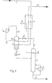
- the gas stream to be separated is fed via line 1 to a heat exchanger 2 under increased pressure and at approximately ambient temperature, in which it is cooled to the extent that the majority of the hydrocarbons to be separated, that is to say the C 2+ or C 3+ hydrocarbon, is condensed.
- the partially condensed gas stream is subjected to a phase separation in a separator 3, the condensate being fed via line 4 to a rectification column 5, in which it is converted into a C 2+ or C 3+ fraction, which is the product stream via line 6 from the Bottom of the column is withdrawn and broken down into a residual gas stream 7 containing lower boiling fractions.
- the rectification is carried out using head cooling 8 operated with external cooling and a bottom heater 9, for example heated with low pressure steam, in which a partial stream of the bottom product branched off from line 6 is heated and then returned to the column bottom.
- the streams drawn off via the lines 4 and 10 from the separator 3 or via line 7 from the rectification column 5 can optionally be heated or cooled to suitable temperature levels before further processing, which can be done, for example, in the heat exchanger 2.
- suitable temperature levels for the currents in lines 4 and 7, this is indicated by dashed lines 14 and 15, respectively.
- the external cooling requirement for the process is covered by a cooling circuit, which is indicated schematically by 16 and which cools the gas mixture in the heat exchanger 2 together with process streams to be heated.
- the gas stream to be broken down in line 1 is under a relatively high pressure. After the condensate has been separated off in the separator 3, it is therefore expanded to the rectification pressure in a throttle valve 17 before being fed into the rectification 5.
- the gaseous fraction from the separator 3 is drawn off via line 18, expanded in the valve 19 to the pressure of the residual gas in line 17 and, after heating in the heat exchanger 20, mixed with the residual gas from line 7 with the residual gas from line 7 before the mixture Turbine 11 is fed.
- the heating in the heat exchanger 20 not only transfers the cold obtained in the throttle relaxation 19 to the gaseous fraction in the separator 3, but also, as an essential moment, causes the gaseous fraction to be heated above the dew point, so that when mixed with the residual gas fraction 7 no condensation occurs.
- the gaseous fraction in the throttle valve 19 is expanded, only a small pressure difference will generally have to be bridged, so that the use of a separate turbine is usually not worthwhile for economic reasons.
- the use of an expansion turbine may well be considered in individual cases in order to utilize the additional cooling capacity that can be achieved to increase the yield or to reduce the need for external cooling.
- the mixture which has been expanded in the turbine 11 is also warmed up inside the separator 3 against its gaseous fraction before it is warmed up against raw gas in the heat exchanger 2.
- the peak cold obtained during the relaxation is introduced into the gaseous fraction in a targeted manner, which means that it is still there Condense contained higher hydrocarbons to a particularly large extent without the condensate drawn off via line 4 being subcooled at the same time.
- a refinery gas is introduced via line 1 at a pressure of 29.2 bar and a temperature of 313 K. It contains 12.2% hydrogen (percentages in each case refer to mol%), 36.5% methane, 9.8% ethylene, 13.6% ethane, 13.6% propylene, 4.3% propane, 3, 9% C 4+ hydrocarbons and 6.1% inert (nitrogen, CO, C0 2 ).
- the gas is separated from the condensed constituents at a pressure of 29 bar in the separator 3.
- the condensate drawn off via line 4 contains 0.5% hydrogen, 18.2% methane, 14.7% ethylene, 23.2% ethane, 25.6% propylene, 8.1% propane, 7.5% C 4+ -Hydrocarbons and 2.2% inert. It is relaxed in valve 17 to the rectification pressure of 27 bar. The rectification is carried out at a bottom temperature of 346 K and a head temperature of 250 K. This results in a C 3+ product stream in the sump, which contains 1% ethane, 61.4% propylene, 19.5% propane and 18.1% C 4+ hydrocarbon. This stream contains 98.6% of the C 3 hydrocarbons fed via line 1.
- a gas stream which contains 0.9% hydrogen, 31.0% methane, 25.9% ethylene, 38.8% ethane, 0.5% C 3 hydrocarbons and 3.8% inert is withdrawn as the top product of the rectification.
- This gas stream is mixed with the gaseous fraction from the separator 3 after it has been expanded to a pressure of 27.2 bar in the throttle valve 19 and warmed in the heat exchanger 20 against the non-expanded gaseous fraction.
- the turbine exhaust gas cools down to a temperature of 191 K. It is first heated to 207 K against the gaseous fraction in separator 3 and finally heated to 310 K in the heat exchanger 2 against raw gas to be cooled, before it is released at a pressure of 5.7 bar.
- the exemplary embodiment shown in FIG. 3 differs from the above essentially in that the rectification is carried out under higher pressure than the pressure prevailing in the separator 3. Therefore, the condensate withdrawn from the separator 3. sat 4 pumped by a liquid pump 21 to the increased rectification pressure.
- the top product of the rectification withdrawn via line 7 must be expanded to its pressure before mixing with the gaseous fraction from the separator 3, for which purpose a throttle valve 22 is provided.
- the relaxed overhead product is introduced into the separator 3 above the heat exchanger 20.
- a refinery gas containing 20.1% hydrogen, 31.2% methane, 13.3% ethylene, 16.9% ethane, 5.2% propylene, 1.8% propane Contains 9% C 4+ hydrocarbons, 0.1% sulfur compounds and 10.5% inert at a pressure of 16.2 bar and a temperature of 288 K via line 1 into the system.
- the gas from which C 2+ hydrocarbons are to be recovered is cooled to 175 K in heat exchanger 2 and then passed into separator 3. That about Lei device 4 drawn off condensate is pumped to the rectification pressure of 32 bar in the pump 21 and fed into the column 5, which is operated at a top temperature of 180 K and a bottom temperature of 285 K.
- This condensate contains 0.3% hydrogen, 20.1% methane, 26.7% ethylene, 35.0% ethane, 10.9% propylene, 3.8% propane, 1.8% C 4+ hydrocarbons, 0 , 2% sulfur compounds and 1.2% inert.
- Via line 6 is a 'product stream with only 70 ppm methane and 33.8% ethylene, 45.0% ethane, 14.0% propylene, 4.8% propane, 2.2% C 4+ hydrocarbons and 0.2 % Sulfur compounds deducted.
- the C 2 yield is 96.6% (based on the C 2 content in the gas stream 1 to be separated).
- the residual gas from the rectification contains 1.6% hydrogen, 91.0% methane, 2.1% ethylene, 0.3% ethane and 5.0 inert.
- a temperature of 180 K it is drawn off via line 7, expanded to 16 bar in valve 22 and introduced into separator 3.
- the gas mixture which forms in the upper region of the separator 3 is expanded in the turbine 11 to a pressure of 8.5 bar, a temperature of 140 K being established.
- This peak cold is transferred to the gaseous fraction by means of the heat exchanger 20 located in the separator 3, whereupon the expanded gas is passed to the heat exchanger 2 at a temperature of 170 K, before finally being conducted via line 13 at a temperature of 285 K and a pressure of 7 , 9 bar is released.
- the exemplary embodiment shown in FIG. 4 shows a variant of the process according to the invention, in which a C 5+ separation is carried out from the gas mixture in a first process step.
- the feed stream 1 is first cooled in a heat exchanger 23 only to such an extent that the majority of the C 5+ hydrocarbons condense. That partially cooled mixture is led out of the heat exchanger 23 at an intermediate temperature, subjected to phase separation in a separator 24, the condensed portions being separated off via line 25, drawn off via line 26 after partial heating in the heat exchanger 23 and being fed to a rectification.
- the gaseous portion of the gas stream is withdrawn from the separator 24 via line 27, cooled again in the heat exchanger 23 and finally fed to the separator 28, which corresponds to the separator 3 of the previously described exemplary embodiments.
Landscapes
- Engineering & Computer Science (AREA)
- Chemical & Material Sciences (AREA)
- Organic Chemistry (AREA)
- Physics & Mathematics (AREA)
- General Engineering & Computer Science (AREA)
- Thermal Sciences (AREA)
- Mechanical Engineering (AREA)
- Oil, Petroleum & Natural Gas (AREA)
- Water Supply & Treatment (AREA)
- Analytical Chemistry (AREA)
- General Chemical & Material Sciences (AREA)
- Chemical Kinetics & Catalysis (AREA)
- Separation By Low-Temperature Treatments (AREA)
- Chemical Vapour Deposition (AREA)
- Chemically Coating (AREA)
- Production Of Liquid Hydrocarbon Mixture For Refining Petroleum (AREA)
Applications Claiming Priority (2)
| Application Number | Priority Date | Filing Date | Title |
|---|---|---|---|
| DE3445994 | 1984-12-17 | ||
| DE19843445994 DE3445994A1 (de) | 1984-12-17 | 1984-12-17 | Verfahren zur gewinnung von c(pfeil abwaerts)2(pfeil abwaerts)(pfeil abwaerts)+(pfeil abwaerts)- oder von c(pfeil abwaerts)3(pfeil abwaerts)(pfeil abwaerts)+(pfeil abwaerts)-kohlenwasserstoffen |
Publications (3)
| Publication Number | Publication Date |
|---|---|
| EP0185252A2 true EP0185252A2 (fr) | 1986-06-25 |
| EP0185252A3 EP0185252A3 (en) | 1986-07-30 |
| EP0185252B1 EP0185252B1 (fr) | 1989-10-11 |
Family
ID=6253000
Family Applications (1)
| Application Number | Title | Priority Date | Filing Date |
|---|---|---|---|
| EP85115406A Expired EP0185252B1 (fr) | 1984-12-17 | 1985-12-04 | Procédé pour la récupération d'hydrocarbures en C2+ ou C3+ |
Country Status (6)
| Country | Link |
|---|---|
| US (1) | US4675036A (fr) |
| EP (1) | EP0185252B1 (fr) |
| AU (1) | AU588558B2 (fr) |
| CA (1) | CA1250222A (fr) |
| DE (2) | DE3445994A1 (fr) |
| NO (1) | NO855064L (fr) |
Cited By (1)
| Publication number | Priority date | Publication date | Assignee | Title |
|---|---|---|---|---|
| CN111886464A (zh) * | 2018-01-11 | 2020-11-03 | 1304338阿尔伯塔有限公司 | 从炼油厂燃料气流回收lpg和冷凝物的方法 |
Families Citing this family (7)
| Publication number | Priority date | Publication date | Assignee | Title |
|---|---|---|---|---|
| NO166934C (no) * | 1984-12-17 | 1991-09-18 | Linde Ag | Fremgangsmaate for utskillelse av c2+-, c3+- eller c4+ hydrocarboner fra en gasstroem som inneholder lette hydrocarboner og eventuelt bestanddeler med lavere kokepunkt enn methan |
| US5287703A (en) * | 1991-08-16 | 1994-02-22 | Air Products And Chemicals, Inc. | Process for the recovery of C2 + or C3 + hydrocarbons |
| AR007346A1 (es) * | 1996-06-05 | 1999-10-27 | Shell Int Research | Un metodo para separar dioxido de carbono, etano y componentes mas pesados de una corriente de gas natural a alta presion |
| US6343487B1 (en) | 2001-02-22 | 2002-02-05 | Stone & Webster, Inc. | Advanced heat integrated rectifier system |
| RU2272973C1 (ru) * | 2004-09-24 | 2006-03-27 | Салават Зайнетдинович Имаев | Способ низкотемпературной сепарации газа (варианты) |
| US10436505B2 (en) * | 2014-02-17 | 2019-10-08 | Black & Veatch Holding Company | LNG recovery from syngas using a mixed refrigerant |
| CN108218658B (zh) * | 2018-03-20 | 2023-12-19 | 浙江省天正设计工程有限公司 | 一种集成乙炔回收利用装置及回收工艺 |
Family Cites Families (15)
| Publication number | Priority date | Publication date | Assignee | Title |
|---|---|---|---|---|
| US2966402A (en) * | 1954-08-26 | 1960-12-27 | Carbonic Dev Corp | Treatment of natural gas in distribution systems |
| US2880592A (en) * | 1955-11-10 | 1959-04-07 | Phillips Petroleum Co | Demethanization of cracked gases |
| US3319429A (en) * | 1965-11-22 | 1967-05-16 | Air Prod & Chem | Methods for separating mixtures of normally gaseous materials |
| US3622504A (en) * | 1969-01-10 | 1971-11-23 | Hydrocarbon Research Inc | Separation of heavier hydrocarbons from natural gas |
| US3516261A (en) * | 1969-04-21 | 1970-06-23 | Mc Donnell Douglas Corp | Gas mixture separation by distillation with feed-column heat exchange and intermediate plural stage work expansion of the feed |
| DE2849344C2 (de) * | 1978-11-14 | 1987-01-29 | Linde Ag, 6200 Wiesbaden | Verfahren zur Abtrennung einer C↓2↓↓+↓-Kohlenwasserstoff-Fraktion aus Erdgas |
| IT1136894B (it) * | 1981-07-07 | 1986-09-03 | Snam Progetti | Metodo per il recupero di condensati da una miscela gassosa di idrocarburi |
| IT1137281B (it) * | 1981-07-07 | 1986-09-03 | Snam Progetti | Metodo per il recupero di condensati da gas naturale |
| US4410342A (en) * | 1982-05-24 | 1983-10-18 | United States Riley Corporation | Method and apparatus for separating a liquid product from a hydrocarbon-containing gas |
| US4456461A (en) * | 1982-09-09 | 1984-06-26 | Phillips Petroleum Company | Separation of low boiling constituents from a mixed gas |
| US4519825A (en) * | 1983-04-25 | 1985-05-28 | Air Products And Chemicals, Inc. | Process for recovering C4 + hydrocarbons using a dephlegmator |
| US4519824A (en) * | 1983-11-07 | 1985-05-28 | The Randall Corporation | Hydrocarbon gas separation |
| US4479871A (en) * | 1984-01-13 | 1984-10-30 | Union Carbide Corporation | Process to separate natural gas liquids from nitrogen-containing natural gas |
| DE3408760A1 (de) * | 1984-03-09 | 1985-09-12 | Linde Ag, 6200 Wiesbaden | Verfahren zur gewinnung von c(pfeil abwaerts)3(pfeil abwaerts)(pfeil abwaerts)+(pfeil abwaerts)-kohlenwasserstoffen |
| NO166934C (no) * | 1984-12-17 | 1991-09-18 | Linde Ag | Fremgangsmaate for utskillelse av c2+-, c3+- eller c4+ hydrocarboner fra en gasstroem som inneholder lette hydrocarboner og eventuelt bestanddeler med lavere kokepunkt enn methan |
-
1984
- 1984-12-17 DE DE19843445994 patent/DE3445994A1/de not_active Withdrawn
-
1985
- 1985-12-04 DE DE8585115406T patent/DE3573596D1/de not_active Expired
- 1985-12-04 EP EP85115406A patent/EP0185252B1/fr not_active Expired
- 1985-12-16 NO NO855064A patent/NO855064L/no unknown
- 1985-12-17 CA CA000497909A patent/CA1250222A/fr not_active Expired
- 1985-12-17 US US06/809,957 patent/US4675036A/en not_active Expired - Fee Related
- 1985-12-17 AU AU51340/85A patent/AU588558B2/en not_active Ceased
Cited By (1)
| Publication number | Priority date | Publication date | Assignee | Title |
|---|---|---|---|---|
| CN111886464A (zh) * | 2018-01-11 | 2020-11-03 | 1304338阿尔伯塔有限公司 | 从炼油厂燃料气流回收lpg和冷凝物的方法 |
Also Published As
| Publication number | Publication date |
|---|---|
| CA1250222A (fr) | 1989-02-21 |
| EP0185252B1 (fr) | 1989-10-11 |
| DE3573596D1 (en) | 1989-11-16 |
| EP0185252A3 (en) | 1986-07-30 |
| AU5134085A (en) | 1986-06-26 |
| AU588558B2 (en) | 1989-09-21 |
| DE3445994A1 (de) | 1986-06-19 |
| NO855064L (no) | 1986-06-18 |
| US4675036A (en) | 1987-06-23 |
Similar Documents
| Publication | Publication Date | Title |
|---|---|---|
| DE68904277T2 (de) | Verfahren zur entwaesserung, entsaeuerung und zur abtrennung eines kondensates von einem erdgas. | |
| DE69618736T2 (de) | Verfahren und Vorrichtung zur Verflüssigung und Behandlung von Erdgas | |
| EP0185253B1 (fr) | Procédé et appareil pour la récupération d'hydrocarbures en C2+ ou C3+ | |
| DE3781556T2 (de) | Verfahren zur rueckgewinnung und reinigung von c3-c4+-kohlenwasserstoffen durch phasentrennung und dephlegmierung. | |
| DE2724365C3 (de) | Verfahren zum Trennen eines C4 -Kohlenwasserstoffgemisches durch extraktive Destillation | |
| DE3441307A1 (de) | Verfahren zur abtrennung einer c(pfeil abwaerts)2(pfeil abwaerts)(pfeil abwaerts)+(pfeil abwaerts)-kohlenwasserstoff-fraktion aus erdgas | |
| EP0318504B1 (fr) | Procédé pour séparer d'un melange gazeux des hydrocarbures lourds | |
| EP0153984B1 (fr) | Procédé et dispositif pour la récupération d'hydrocarbures en C3 | |
| DE69909143T2 (de) | Trennung von Kohlenstoffmonoxid aus stickstoffverschmutzten, Wasserstoff und Methan enthaltenden Gasgemischen | |
| DE60009990T2 (de) | Verfahren und Vorrichtung zur Trennung von Mischungen von Wasserstoff und Kohlenmonoxid | |
| DE3445995A1 (de) | Verfahren zur gewinnung von c(pfeil abwaerts)2(pfeil abwaerts)(pfeil abwaerts)+(pfeil abwaerts)- oder von c(pfeil abwaerts)3(pfeil abwaerts)(pfeil abwaerts)+(pfeil abwaerts)-kohlenwasserstoffen | |
| EP4014001B1 (fr) | Procédé de traitement d'un mélange gazeux contenant du méthane et de l'azote | |
| EP0185252A2 (fr) | Procédé pour la récupération d'hydrocarbures en C2+ ou C3+ | |
| DE3227477C2 (de) | Tieftemperatur-Verfahren zur Entfernung von sauren Gasen aus natürlichen oder synthetischen Gasgemischen | |
| DE3227465C2 (de) | Tieftemperatur-Verfahren zur getrennten Entfernung von sauren Gasen aus natürlichen oder synthetischen Gasgemischen | |
| DE2932561A1 (de) | Verfahren und vorrichtung zum zerlegen eines gasgemisches | |
| EP0228623B1 (fr) | Procédé de séparation d'hydrocarbures en C5+ d'un courant gazeux | |
| DE2702424A1 (de) | Verfahren zum trennen von aethylen und aethan | |
| DE1296724C2 (de) | Verfahren zur verhinderung der eis- und hydratbildung bei der trennung eines wasserhaltigen, leichte kohlenwasserstoffe enthaltenden gemisches durch fraktionierung | |
| DE4417584A1 (de) | Verfahren zur Trennung von C¶2¶/C¶3¶-Kohlenwasserstoffen in Ethylenanlagen | |
| EP1032798B1 (fr) | Procede et installation pour la separation d'hydrocarbures c2 ou c2+ | |
| DE2931012A1 (de) | Verfahren zur gewinnung von reinbenzol | |
| DE2917505C2 (fr) | ||
| DE3626561A1 (de) | Verfahren zum abtrennen von c(pfeil abwaerts)2(pfeil abwaerts)(pfeil abwaerts)+(pfeil abwaerts)- oder von c(pfeil abwaerts)3(pfeil abwaerts)(pfeil abwaerts)+(pfeil abwaerts)- kohlenwasserstoffen aus einem gasgemisch | |
| DE2608404A1 (de) | Verfahren und vorrichtung zur trennung von stoffgemischen durch rektifikation |
Legal Events
| Date | Code | Title | Description |
|---|---|---|---|
| PUAI | Public reference made under article 153(3) epc to a published international application that has entered the european phase |
Free format text: ORIGINAL CODE: 0009012 |
|
| PUAL | Search report despatched |
Free format text: ORIGINAL CODE: 0009013 |
|
| AK | Designated contracting states |
Kind code of ref document: A2 Designated state(s): DE FR GB IT NL SE |
|
| RHK1 | Main classification (correction) |
Ipc: C07C 7/04 |
|
| AK | Designated contracting states |
Kind code of ref document: A3 Designated state(s): DE FR GB IT NL SE |
|
| 17P | Request for examination filed |
Effective date: 19860702 |
|
| 17Q | First examination report despatched |
Effective date: 19870309 |
|
| GRAA | (expected) grant |
Free format text: ORIGINAL CODE: 0009210 |
|
| AK | Designated contracting states |
Kind code of ref document: B1 Designated state(s): DE FR GB IT NL SE |
|
| PG25 | Lapsed in a contracting state [announced via postgrant information from national office to epo] |
Ref country code: SE Effective date: 19891011 Ref country code: NL Effective date: 19891011 Ref country code: IT Free format text: LAPSE BECAUSE OF FAILURE TO SUBMIT A TRANSLATION OF THE DESCRIPTION OR TO PAY THE FEE WITHIN THE PRESCRIBED TIME-LIMIT;WARNING: LAPSES OF ITALIAN PATENTS WITH EFFECTIVE DATE BEFORE 2007 MAY HAVE OCCURRED AT ANY TIME BEFORE 2007. THE CORRECT EFFECTIVE DATE MAY BE DIFFERENT FROM THE ONE RECORDED. Effective date: 19891011 Ref country code: GB Effective date: 19891011 Ref country code: FR Free format text: THE PATENT HAS BEEN ANNULLED BY A DECISION OF A NATIONAL AUTHORITY Effective date: 19891011 |
|
| REF | Corresponds to: |
Ref document number: 3573596 Country of ref document: DE Date of ref document: 19891116 |
|
| EN | Fr: translation not filed | ||
| NLV1 | Nl: lapsed or annulled due to failure to fulfill the requirements of art. 29p and 29m of the patents act | ||
| GBV | Gb: ep patent (uk) treated as always having been void in accordance with gb section 77(7)/1977 [no translation filed] | ||
| PLBE | No opposition filed within time limit |
Free format text: ORIGINAL CODE: 0009261 |
|
| STAA | Information on the status of an ep patent application or granted ep patent |
Free format text: STATUS: NO OPPOSITION FILED WITHIN TIME LIMIT |
|
| PG25 | Lapsed in a contracting state [announced via postgrant information from national office to epo] |
Ref country code: DE Effective date: 19900901 |
|
| 26N | No opposition filed |