EP0185288A2 - Packmittel - Google Patents
Packmittel Download PDFInfo
- Publication number
- EP0185288A2 EP0185288A2 EP85115646A EP85115646A EP0185288A2 EP 0185288 A2 EP0185288 A2 EP 0185288A2 EP 85115646 A EP85115646 A EP 85115646A EP 85115646 A EP85115646 A EP 85115646A EP 0185288 A2 EP0185288 A2 EP 0185288A2
- Authority
- EP
- European Patent Office
- Prior art keywords
- ring
- screw thread
- thread
- screw
- angle
- Prior art date
- Legal status (The legal status is an assumption and is not a legal conclusion. Google has not performed a legal analysis and makes no representation as to the accuracy of the status listed.)
- Granted
Links
Images

Classifications
-
- B—PERFORMING OPERATIONS; TRANSPORTING
- B65—CONVEYING; PACKING; STORING; HANDLING THIN OR FILAMENTARY MATERIAL
- B65D—CONTAINERS FOR STORAGE OR TRANSPORT OF ARTICLES OR MATERIALS, e.g. BAGS, BARRELS, BOTTLES, BOXES, CANS, CARTONS, CRATES, DRUMS, JARS, TANKS, HOPPERS, FORWARDING CONTAINERS; ACCESSORIES, CLOSURES, OR FITTINGS THEREFOR; PACKAGING ELEMENTS; PACKAGES
- B65D41/00—Caps, e.g. crown caps or crown seals, i.e. members having parts arranged for engagement with the external periphery of a neck or wall defining a pouring opening or discharge aperture; Protective cap-like covers for closure members, e.g. decorative covers of metal foil or paper
- B65D41/32—Caps or cap-like covers with lines of weakness, tearing-strips, tags, or like opening or removal devices, e.g. to facilitate formation of pouring openings
- B65D41/34—Threaded or like caps or cap-like covers provided with tamper elements formed in, or attached to, the closure skirt
- B65D41/3423—Threaded or like caps or cap-like covers provided with tamper elements formed in, or attached to, the closure skirt with flexible tabs, or elements rotated from a non-engaging to an engaging position, formed on the tamper element or in the closure skirt
- B65D41/3438—Threaded or like caps or cap-like covers provided with tamper elements formed in, or attached to, the closure skirt with flexible tabs, or elements rotated from a non-engaging to an engaging position, formed on the tamper element or in the closure skirt the tamper element being formed separately but connected to the closure
Definitions
- the invention relates to a packaging which consists of a bottle-like container with a round mouth part and a screw cap which fits onto the mouth part, the mouth part having a bead ring, an external screw thread and an annular pouring rim.
- the lower edge of the closure cap is connected via a plurality of shear webs to an outwardly projecting annular collar which has resiliently formed locking teeth which engage with locking teeth which are arranged on the neck of the container when screwed on.
- the screwed-on cap can only be removed from the container neck by shearing off the shear webs.
- the cap is preferably made of a thermoplastic, e.g. Polyethylene, and can be produced in one piece by the injection molding process.
- the object of the invention is to provide a packaging consisting of a container and a closure cap, the closure of which is structurally simplified and prevents manipulation.
- An essential feature of the packaging material according to the invention is the design of the vessel mouth part, which has an externally arranged screw thread, a bead ring arranged below the screw thread and an annular pouring rim arranged above the screw thread.
- the screw thread is single-thread to four-thread, preferably single-thread; the pitch of the thread is 2.5 to 6.0 mm, preferably 3.0 to 5.0 mm.
- the screw thread is preferably designed as a saw thread or as a trapezoidal thread.
- the bead ring is flared downwards, the angle of inclination being 135 to 150, preferably 140 to 145 degrees.
- the pouring rim is tapered downwards, the angle of inclination being 130 to 145, preferably 135 to 140 degrees.
- the angle of inclination is the angle between the outer edge of the conical part and the vertical axis of the mouth part.
- Another essential feature of the packaging according to the invention is the design, the screw cap, which can be screwed to the mouth part.
- the lower edge of this cap is designed as a bell-shaped extension, which extends over the bead ring of the mouth part.
- This design of the cap ensures easy handling of the packaging material without the risk of destroying the double ring described below.
- a base ring consisting of segments is arranged in the upper part, which preferably has 6 to 50 segments, and there is an undercut in the lower part.
- a ring (retaining ring) is held between the base ring and the undercut, which is connected to another ring (locking ring) via elastic webs; the latter has a V-shaped profile and is preferably arranged in the same plane as the first-mentioned retaining ring.
- the number of elastic webs is expediently 3 to 24, preferably 6 to 12.
- a seal is arranged in the upper part of the screw cap, which closes the mouth part of the bottle-like vessel when it is screwed on.
- the seal is preferably designed as a flat seal, cone seal or cup seal; it can also be designed in the form of a metering device or a measuring device.
- the bottle-like vessel preferably consists of glass, in particular a glass with medium hydrolytic resistance (glass type III according to the European Pharmacopoeia Volume II, 1975).
- the bottle-like vessel conveniently has a volume of 5 ml to 10 1, preferably 100 ml to 2.5 1, the mouth portion of the vessel has an inner diameter of 10 to 70 mm, preferably 18 to 2 8 mm.
- the outer diameter of the mouth part is 15 to 80 mm, preferably 32 to 45 mm.
- a special design of the glass vessel consists in that it is coated with a protective layer made of a transparent plastic, for example polyvinyl chloride. The thickness of the protective layer is in the range of 0.4 to 0.6 mm.
- the screw cap preferably consists of a thermoplastic, in particular a polyolefin such as polyethylene or polypropylene.
- the double ring composed of the retaining ring, connecting webs and locking ring is made of the same material.
- the material of the screw cap and that of the double ring preferably have different colors; the materials preferably also differ in their hardness and elasticity.
- Figure 1 shows a partially sectioned overall view of the screw cap and Figure 2 shows an overall view of the mouth part of the bottle-like vessel.
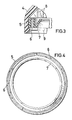
- Figure 3 is a detail from Figure 1, and Figure 4 shows a top view of the isolated double ring.
- the screw cap has a bell-shaped extension 4 in the lower part, on the inside of which there is a base ring consisting of segments 8 in the upper part and a rear in the lower part intersection 9 is located. Between the segments 8 and undercut 9, a double ring is held, which consists of a retaining ring 5 and a ring 7, which are connected to one another via elastic webs 6. In the upper part of the screw cap, a seal 10 is arranged.
- the mouth part of the bottle-like vessel has a screw thread 1, under which a bead ring 2 is arranged and above which there is a pouring rim 3.
- the screw thread is designed as a trapezoidal thread.
- the bead ring 2 is flared downwards, and its outer edge forms the angle a with the vertical axis.
- the pouring rim 3 is tapered downwards, and its outer edge forms the angle ⁇ with the vertical axis.
- FIG. 3 shows the cross section of the double ring, which is composed of a retaining ring 5, a locking ring 7 and connecting webs 6.
- the double ring is fastened between the segments 8 and undercut 9.
- the double ring consists of a retaining ring 5 and a locking ring 7 and the rings mentioned are connected to one another by means of webs 6. Retaining ring 5 and locking ring 7 are arranged in the same plane.
Landscapes
- Engineering & Computer Science (AREA)
- Mechanical Engineering (AREA)
- Closures For Containers (AREA)
Abstract
Description
- Die Erfindung betrifft ein Packmittel, das aus einem flaschenartigen Gefäß mit rundem Mündungsteil und einer auf das Mündungsteil passenden Schraubverschlußkappe besteht, wobei das Mündungsteil einen Wulstring, ein außen liegendes Schraubgewinde und einen ringförmigen Gießrand aufweist.
- Ein flaschenartiger Behälter mit einer Verschlußkappe, die auf das Gewinde des Behälterhalses aufschraubbar ist, ist bereits bekannt (s. europäische Patentschrift 16 419 = US-Patentschrift 4 326 639). Der untere Rand der Verschlußkappe ist über eine Vielzahl von Scherstegen mit einem nach außen abstehenden ringförmigen Kragen verbunden, der federnd angeformte Sperrzähne aufweist, welche beim Zuschrauben mit Rastzähnen, die am Behälterhals angeordnet sind, in Eingriff treten. Die aufgeschraubte Verschlußkappe ist nur unter Abscheren der Scherstege vom Behälterhals zu entfernen. Die Verschlußkappe besteht vorzugsweise aus einem thermoplastischen Kunststoff, z.B. Polyethylen, und läßt sich nach dem Spritzgießverfahren in einem Stück herstellen.
- Aufgabe der Erfindung ist die Bereitstellung eines aus Gefäß und Verschlußkappe bestehenden Packmittels, dessen Verschluß konstruktiv vereinfacht ist und Manipulationen ausschließt.
- Die Erfindung betrifft ein Packmittel, bestehend aus einem flaschenartigen Gefäß mit rundem Mündungsteil, das einen Wulstring, ein außen liegendes Schraubgewinde und einen ringförmigen Gießrand aufweist, und einer auf das Mündungsteil passenden Schraubverschlußkappe, das dadurch gekennzeichnet ist, daß
- a) das Schraubgewinde ein Gewinde (1) mit einer Steigung von 2,5 bis 6,0 m7, ist,
- b) der unterhalb des Schraubgewindes angeordnete Wulstring (2) nach unten konisch erweitert ist, wobei der Neigungswinkel(a) 135 bis 150 Grad beträgt,
- c) der oberhalb des Schraubgewindes angeordnete Gießrand (3) nach unten konisch verjüngt ist, wobei der Neigungswinkel (ß) 130 bis 145 Grad beträgt,
- d) die Schraubverschlußkappe im unteren Teil eine glockenförmige Erweiterung (4) aufweist, die über den Wulstring (2) des Mündungsteiles übergreift,
- e) an der Innenseite der glockenförmigen Erweiterung (4) ein Ring (5) angeordnet ist, der über elastische Stege (6) mit einem weiteren Ring (7) verbunden ist, der ein V-förmiges Profil aufweist.
- Ein wesentliches Merkmal des erfindungsgemäßen Packmittels ist die Gestaltung des Gefäßmündungsteils, das ein außen angeordnetes Schraubgewinde, einen unterhalb des Schraubgewindes angeordneten Wulstring und einen oberhalb des Schraubgewindes angeordneten ringförmigen Gießrand aufweist. Das Schraubgewinde ist eingängig bis viergängig, vorzugsweise eingängig; die Steigung des Gewindes beträgt 2,5 bis 6,0 mm, vorzugsweise 3,0 bis 5,0 mm. Das Schraubgewinde ist vorzugsweise als Sägegewinde oder als Trapezgewinde ausgebildet. Der Wulstring ist nach unten konisch erweitert, wobei der Neigungswinkel 135 bis 150, vorzugsweise 140 bis 145 Grad beträgt. Der Gießrand ist nach unten konisch verjüngt, wobei der Neigungswinkel 130 bis 145, vorzugsweise 135 bis 140 Grad beträgt. (Mit Neigungswinkel ist jeweils der Winkel zwischen der äußeren Kante des konischen Teils und der senkrechten Achse des Mündungsteils bezeichnet.) Ein weiteres wesentliches Merkmal des erfindungsgemäßen Packmittels ist die Gestaltung, der Schraubverschlußkappe, die mit dern MündungstEil verschraubbar ist. Der untere Rand dieser Kappe ist als glockenförmige Erweiterung ausgestaltet, die über den Wulstring des Mündungsteils übergreift. Diese Ausgestaltung der Kappe gewährleistet eine einfache Handhabung des Packmittels ohne die Gefahr der Zerstörung des nachstehend beschriebenen Doppelringes. An der Innenseite der glockenförmigen Erweiterung ist im oberen Teil ein aus Segmenten bestehender Sockelring angeordnet, der vorzugsweise 6 bis 50 Segmente aufweist, und im unteren Teil befindet sich eine Hinterschneidung. Zwischen dem Sockelring und der Hinterschneidung wird ein Ring (Haltering) gehalten, der über elastische Stege mit einem weiteren Ring (Schließring) verbunden ist; letzterer weist ein V-förmiges Profil auf und ist vorzugsweise in der gleichen Ebene wie der erstgenannte Haltering angeordnet. Die Zahl der elastischen Stege beträgt zweckmäßigerweise 3 bis 24, vorzugsweise 6 bis 12. Beim Zuschrauben der Verschlußkappe gleitet der innen liegende Teil des Schließrings über den Wulstring des Mündungsteils und rastet unter ihm ein. Beim Aufschrauben werden die Scherstege zerrissen, und der Schließring verbleibt unter dem Wulstring. Infolge der Anordnung und besonderen Form des aus Haltering und Schließring bestehenden Doppelringes sind Manipulationen des Verschlusses praktisch ausgeschlossen.
- Im oberen Teil der SchrauDverschlußkape ist eine Dichtung angeordnet, die beim Zuschrauben das Mündungsteil des flaschenartigen Gefäßes verschließt. Die Dichtung ist vorzugsweise als Flachdichtung, Konusdichtung oder Napfdichtung ausgebildet; sie kann auch in Form einer Dosiervorrichtung oder einer Meßvorrichtung ausgestaltet sein.
- Das flaschenartige Gefäß besteht vorzugsweise aus Glas, insbesondere einem Glas mit mittlerer hydrolytischer Resistenz (Glasart III gemäß Europäischem Arzneibuch Band II, 1975).
- besonders bevorzugt ist gefärbtes Glas. Weitere geeignete Materialien sind Metalle, z.b. Aluminium, sowie thermoplastiscne Kunststoffe, z.B. Polyolefine wie Polyethylen und Polypropylen. Das flaschenartige Gefäß hat zweckmäßigerweise ein Volumen von 5 ml bis 10 1, vorzugsweise 100 ml bis 2,5 1. Das Mündungsteil des Gefäßes weist einen inneren Durchmesser von 10 bis 70 mm, vorzugsweise 18 bis 28 mm auf. Der äußere Durchmesser des Mündungsteils beträgt 15 bis 80 mm, vorzugsweise 32 bis 45 mm. Eine besondere Ausgestaltung des aus Glas bestehenden Gefäßes besteht darin, daß es mit einer Schutzschicht aus einem transparenten Kunststoff, z.B. Polyvinylchlorid, ummantelt ist. Die Stärke der Schutzschicht liegt im Bereich von 0,4 bis 0,6 mm.
- Die Schraubverschlußkappe besteht vorzugsweise aus einem thermoplastischen Kunststoff, insbesondere einem Polyolefin wie Polyethylen oder Polypropylen. Aus dem gleichen Material besteht der aus Haltering, Verbindungsstegen und Schließring zusammengesetzte Doppelring. Das Material der Schraubverschlußkappe und das des Doppelringes weisen vorzugsweise unterschiedliche Farben auf; die Materialien unterscheiden sich vorzugsweise auch in ihrer Härte und Elastizität.
- Das Wesen der Erfindung ist in den Figuren 1 bis 4 dargestellt. Figur 1 zeigt eine teilweise geschnittene Gesamtansicht der Schraubverschlußkappe und Figur 2 eine Gesamtansicht des Mündungsteils des flaschenartigen Gefäßes. Figur 3 ist ein Ausschnitt aus Figur 1, und Figur 4 zeigt eine Aufsicht auf den isolierten Doppelring.
- Aus Fig. 1 ist ersichtlich, daß die Schraubverschlußkappe im unteren Teil eine glockenförmige Erweiterung 4 aufweist, an deren Innenseite sich im oberen Teil ein aus Segmenten 8 bestehender Sockelring und im unteren Teil eine Hinterschneidung 9 befindet. Zwischen den Segmenten 8 und Hinterschneidung 9 wird ein Doppelring gehalten, der aus einem Haltering 5 und einem Senliebring 7 besteht, die über elastische Steie 6 miteinander verunden sind. Im oberen Teil der Schraubverschßkappe ist eine Dichtung 10 angeordnet.
- Nach Fig. 2 weist das Mündungsteil des flaschenartigen Gefäßes ein Schraubgewinde 1 auf, unter dem ein Wulstring 2 angeordnet ist und über dem sich ein Gießrand 3 befindet. Das Schraubgewinde ist als Trapezgewinde ausgestaltet. Der Wulstring 2 ist nach unten konisch erweitert, und seine äußere Kante bildet mit der senkrechten Achse den Winkel a. Der Gießrand 3 ist nach unten konisch verjüngt, und seine äußere Kante bildet mit der senkrechten Achse den Winkel ß.
- In Fig. 3 ist der Querschnitt des Doppelringes hervorgehoben, der zusammengesetzt ist aus einem Haltering 5, einem Schließring 7 und Verbindungsstegen 6. Der Doppelring ist zwischen den Segmenten 8 und Hinterschneidung 9 befestigt.
- Nach Fig. 4 ist in einer Aufsicht auf den isolierten Doppelring erkennbar, daß der Doppelring aus einem Haltering 5 und einem Schließring 7 besteht und die genannten Ringe mittels Stegen 6 miteinander verbunden sind. Haltering 5 und Schließring 7 sind in der gleichen Ebene angeordnet.
Claims (6)
- l. Packmittel , bestehend aus einem flaschenartigen Gefäß mit rundem Mündungsteil, das einen Wulstring, ein außen liegendes Schraubgewinde und einen ringförmigen Gießrand aufweist, und einer auf das Mündungsteil passenden Schraubverschlußkappe, dadurch gekennzeichnet, daßa) das Schraubgewinde ein Gewinde (1) mit einer Steigung von 2,5 bis 6,0 mm ist,b) der unterhalb des Schraubgewindes angeordnete Wulstring (2) nach unten konisch erweitert ist, wobei der Neigungswinkel (a) 135 bis 150 Grad beträgt,c) der oberhalb des Schraubgewindes angeordnete Gießrand nach unten konisch verjüngt ist, wobei der Neigungswinkel (ß) 130 bis 145 Grad beträgt,d) die Schraubverschlußkappe im unteren Teil eine glockenförmige Erweiterung (4) aufweist, die über den Wulstring (2) des Mündungsteils übergreift,e) an der Innenseite der glockenförmigen Erweiterung (4) ein Ring (5) angeordnet ist, der über elastische Stege (6) mit einem weiteren Ring (7) verbunden ist, der ein V-förmiges Profil aufweist.
- 2. Packmittel nach Anspruch 1, dadurch gekennzeichnet, daß das Schraubgewinde ein Sägegewinde oder ein Trapezgewinde ist.
- 3. Packmittel nach Anspruch 1, dadurch gekennzeichnet, daß die Schraubverschlußkappe mit einer Flachdichtung, Konusdichtung oder Napfdichtung (10) ausgerüstet ist.
- 4. Packmittel nach Anspruch 1, dadurch gekennzeichnet, daß die Anzahl der elastischen Stege 3 bis 24 beträgt.
- 5. Packmittel nach Anspruch 1, dadurch gekennzeichnet, daß die Schraubverschlußkappe aus einem thermoplastischen Kunststoff besteht.
- 6. Packmittel nach Anspruch 5, dadurch gekennzeichnet, daß das Material der Schraubverschlußkappe und das der Ringe unterschiedlich gefärbt ist.
Applications Claiming Priority (2)
| Application Number | Priority Date | Filing Date | Title |
|---|---|---|---|
| DE8437538U | 1984-12-21 | ||
| DE8437538U DE8437538U1 (de) | 1984-12-21 | 1984-12-21 | Packmittel |
Publications (3)
| Publication Number | Publication Date |
|---|---|
| EP0185288A2 true EP0185288A2 (de) | 1986-06-25 |
| EP0185288A3 EP0185288A3 (en) | 1988-07-27 |
| EP0185288B1 EP0185288B1 (de) | 1990-09-05 |
Family
ID=6774054
Family Applications (1)
| Application Number | Title | Priority Date | Filing Date |
|---|---|---|---|
| EP85115646A Expired - Lifetime EP0185288B1 (de) | 1984-12-21 | 1985-12-09 | Packmittel |
Country Status (4)
| Country | Link |
|---|---|
| EP (1) | EP0185288B1 (de) |
| DE (2) | DE8437538U1 (de) |
| FR (1) | FR2575138B3 (de) |
| IT (1) | IT206676Z2 (de) |
Cited By (2)
| Publication number | Priority date | Publication date | Assignee | Title |
|---|---|---|---|---|
| EP0261965A3 (en) * | 1986-09-25 | 1989-02-22 | National Plastics Limited | Cap for a container closure cap for a container closure |
| FR3046993A1 (fr) * | 2016-01-27 | 2017-07-28 | United Caps France | Dispositif de bouchage |
Families Citing this family (2)
| Publication number | Priority date | Publication date | Assignee | Title |
|---|---|---|---|---|
| DE3512129A1 (de) * | 1985-04-03 | 1986-10-16 | Georg Menshen & Co Kg, 5950 Finnentrop | Originalitaetsverschluss fuer behaelter u.dgl. |
| DE3701430A1 (de) * | 1987-01-20 | 1988-07-28 | Georg Menshen & Co Kg | Originalitaetsverschluss |
Family Cites Families (2)
| Publication number | Priority date | Publication date | Assignee | Title |
|---|---|---|---|---|
| AR208410A1 (es) * | 1975-04-10 | 1976-12-27 | Tomiati U | Tapa de seguridad |
| DE3224002A1 (de) * | 1982-06-26 | 1983-12-29 | Robert Finke KG, 5950 Finnentrop | Originalitaetsverschluss |
-
1984
- 1984-12-21 DE DE8437538U patent/DE8437538U1/de not_active Expired
-
1985
- 1985-12-09 DE DE8585115646T patent/DE3579570D1/de not_active Expired - Lifetime
- 1985-12-09 EP EP85115646A patent/EP0185288B1/de not_active Expired - Lifetime
- 1985-12-19 IT IT8524210U patent/IT206676Z2/it active
- 1985-12-19 FR FR8518834A patent/FR2575138B3/fr not_active Expired
Cited By (3)
| Publication number | Priority date | Publication date | Assignee | Title |
|---|---|---|---|---|
| EP0261965A3 (en) * | 1986-09-25 | 1989-02-22 | National Plastics Limited | Cap for a container closure cap for a container closure |
| FR3046993A1 (fr) * | 2016-01-27 | 2017-07-28 | United Caps France | Dispositif de bouchage |
| EP3199469A1 (de) * | 2016-01-27 | 2017-08-02 | United Caps France | Verschlussvorrichtung |
Also Published As
| Publication number | Publication date |
|---|---|
| IT206676Z2 (it) | 1987-10-01 |
| FR2575138B3 (fr) | 1987-02-06 |
| DE3579570D1 (de) | 1990-10-11 |
| EP0185288B1 (de) | 1990-09-05 |
| EP0185288A3 (en) | 1988-07-27 |
| FR2575138A3 (fr) | 1986-06-27 |
| IT8524210V0 (it) | 1985-12-19 |
| DE8437538U1 (de) | 1985-03-21 |
Similar Documents
| Publication | Publication Date | Title |
|---|---|---|
| DE19580104B4 (de) | Ausgabeöffnungsanordnung | |
| EP0364783B1 (de) | Verschluss für eine Medikamentenflasche und Verfahren zur Herstellung dieses Verschlusses | |
| DE2411245A1 (de) | Behaelterverschluss | |
| CH630023A5 (de) | Steril verschliessbarer behaelter. | |
| DE1532396A1 (de) | Flaschenverschlusskappe | |
| DE2139910A1 (de) | Behalter mit durch Kronenkork ver schlossenem Gewindemundstuck | |
| CH710317A1 (de) | Blasgeformter Behälter mit Supportring. | |
| EP0185288B1 (de) | Packmittel | |
| CH716103B1 (de) | Drehverschluss mit einem Garantieband und einer unverlierbar gehaltenen Verschlusskappe. | |
| DE1432101A1 (de) | Verbesserter Verteilerverschluss | |
| DE9417846U1 (de) | Universalflaschenverschluß für enterale Überleitungsgeräte | |
| EP0650446A1 (de) | Schraubdeckel. | |
| CH673017A5 (de) | ||
| EP0215202A1 (de) | Verfahren zur Herstellung einer Verschlusskappe aus Kunststoff für flaschenartige Behälter | |
| DE2439414A1 (de) | Kunststoffverschluss fuer flaschen und behaelter | |
| WO2019174733A1 (de) | Spender zur ausgabe eines spendegutes | |
| DE4343442A1 (de) | Vorrichtung zum Öffnen einer Packung | |
| DE2824601A1 (de) | Spruehsiebeinsatz | |
| DE2732523A1 (de) | Steril verschliessbarer behaelter | |
| DE1782178B2 (de) | Schraubverschluß aus Kunststoff für Kunststoff-Flaschen und Konststoff-Behälter | |
| DE2104811A1 (de) | Vorrichtung zur Abgabe von Drogen oder dergl. aus Behältern | |
| DE19827242A1 (de) | Verschlußkappe, insbesondere Schraubkappe aus Kunststoff mit Garantieband | |
| DE2300483A1 (de) | Flasche mit verschlusseinrichtung, insbesondere fuer getraenke | |
| DE8614406U1 (de) | Auftrags- und Verteilungsvorrichtung für eine Creme | |
| DE2356086A1 (de) | Nichtreflektierender strassen-markierungsnagel |
Legal Events
| Date | Code | Title | Description |
|---|---|---|---|
| PUAI | Public reference made under article 153(3) epc to a published international application that has entered the european phase |
Free format text: ORIGINAL CODE: 0009012 |
|
| AK | Designated contracting states |
Kind code of ref document: A2 Designated state(s): DE FR GB IT NL |
|
| PUAL | Search report despatched |
Free format text: ORIGINAL CODE: 0009013 |
|
| AK | Designated contracting states |
Kind code of ref document: A3 Designated state(s): DE FR GB IT NL |
|
| 17P | Request for examination filed |
Effective date: 19881001 |
|
| 17Q | First examination report despatched |
Effective date: 19890530 |
|
| GRAA | (expected) grant |
Free format text: ORIGINAL CODE: 0009210 |
|
| AK | Designated contracting states |
Kind code of ref document: B1 Designated state(s): DE FR GB IT NL |
|
| PG25 | Lapsed in a contracting state [announced via postgrant information from national office to epo] |
Ref country code: NL Effective date: 19900905 |
|
| ITF | It: translation for a ep patent filed | ||
| REF | Corresponds to: |
Ref document number: 3579570 Country of ref document: DE Date of ref document: 19901011 |
|
| ET | Fr: translation filed | ||
| GBT | Gb: translation of ep patent filed (gb section 77(6)(a)/1977) | ||
| NLV1 | Nl: lapsed or annulled due to failure to fulfill the requirements of art. 29p and 29m of the patents act | ||
| PLBE | No opposition filed within time limit |
Free format text: ORIGINAL CODE: 0009261 |
|
| STAA | Information on the status of an ep patent application or granted ep patent |
Free format text: STATUS: NO OPPOSITION FILED WITHIN TIME LIMIT |
|
| 26N | No opposition filed | ||
| ITTA | It: last paid annual fee | ||
| PGFP | Annual fee paid to national office [announced via postgrant information from national office to epo] |
Ref country code: FR Payment date: 19931110 Year of fee payment: 9 |
|
| PGFP | Annual fee paid to national office [announced via postgrant information from national office to epo] |
Ref country code: GB Payment date: 19931119 Year of fee payment: 9 |
|
| PG25 | Lapsed in a contracting state [announced via postgrant information from national office to epo] |
Ref country code: GB Effective date: 19941209 |
|
| GBPC | Gb: european patent ceased through non-payment of renewal fee |
Effective date: 19941209 |
|
| PG25 | Lapsed in a contracting state [announced via postgrant information from national office to epo] |
Ref country code: FR Effective date: 19950831 |
|
| REG | Reference to a national code |
Ref country code: FR Ref legal event code: ST |
|
| PGFP | Annual fee paid to national office [announced via postgrant information from national office to epo] |
Ref country code: DE Payment date: 20041230 Year of fee payment: 20 |