EP0185301A1 - Entraînement par vis sans fin, avec une tige filetée et un ou plusieurs anneaux roulants entourant la tige excentriquement - Google Patents
Entraînement par vis sans fin, avec une tige filetée et un ou plusieurs anneaux roulants entourant la tige excentriquement Download PDFInfo
- Publication number
- EP0185301A1 EP0185301A1 EP19850115735 EP85115735A EP0185301A1 EP 0185301 A1 EP0185301 A1 EP 0185301A1 EP 19850115735 EP19850115735 EP 19850115735 EP 85115735 A EP85115735 A EP 85115735A EP 0185301 A1 EP0185301 A1 EP 0185301A1
- Authority
- EP
- European Patent Office
- Prior art keywords
- spindle
- thread
- rolling ring
- distance
- radius
- Prior art date
- Legal status (The legal status is an assumption and is not a legal conclusion. Google has not performed a legal analysis and makes no representation as to the accuracy of the status listed.)
- Granted
Links
- 238000005096 rolling process Methods 0.000 title claims abstract description 46
- 230000000717 retained effect Effects 0.000 abstract 1
- 239000011324 bead Substances 0.000 description 1
- 230000000694 effects Effects 0.000 description 1
- 230000001771 impaired effect Effects 0.000 description 1
Images

Classifications
-
- F—MECHANICAL ENGINEERING; LIGHTING; HEATING; WEAPONS; BLASTING
- F16—ENGINEERING ELEMENTS AND UNITS; GENERAL MEASURES FOR PRODUCING AND MAINTAINING EFFECTIVE FUNCTIONING OF MACHINES OR INSTALLATIONS; THERMAL INSULATION IN GENERAL
- F16H—GEARING
- F16H25/00—Gearings comprising primarily only cams, cam-followers and screw-and-nut mechanisms
- F16H25/18—Gearings comprising primarily only cams, cam-followers and screw-and-nut mechanisms for conveying or interconverting oscillating or reciprocating motions
- F16H25/20—Screw mechanisms
- F16H25/22—Screw mechanisms with balls, rollers, or similar members between the co-operating parts; Elements essential to the use of such members
- F16H25/2285—Screw mechanisms with balls, rollers, or similar members between the co-operating parts; Elements essential to the use of such members with rings engaging the screw shaft with the inner perimeter, e.g. using inner rings of a ball bearing
- F16H25/229—Eccentric rings with their axis arranged substantially parallel to the screw shaft axis
Definitions
- the invention relates to a spindle drive of the type mentioned in the preamble of the main claim.
- Such a spindle drive is i.a. known from DE-OS 28 39 920.
- the space required for such spindle drives is often very limited, so that any reduction in the size of the nut body carrying the rolling ring or rings, which includes the spindle, taking into account the essential parameters for such a spindle drive, such as Speed, accuracy, freedom from wear, is of great importance.
- the invention is therefore based on the object to provide a spindle drive with the features of the generic term, which has a small nut body and thus a small roller ring or roller rings with given spindle dimensions compared to known spindle drives, without the effect and function of the spindle drive being impaired.
- This object is achieved in a spindle drive according to the preamble of the main claim in that the size of the intersection distance between the closest intersection points of the outer helix or the parallel helixes of the spindle thread and the adjacent inner base circle or root circles of the rolling ring between 0 and 8 % of the radius' of the base circle or circles of the rolling ring, ie the intersection distance converges to zero and the radius is up to 8% of this ideal value.
- the sub-claims contain features that improve and further develop these features of the main claim.
- the characterizing part of the main claim gives a technical teaching, which gives the skilled person both mathematically and graphically the teaching, the task set, the smallest possible rolling ring for a given flank angle, for a given pitch of the spindle thread, for a given diameter of the thread core and the outside diameter of the thread.
- crossing points are defined as points with the smallest distance between two straight lines. This shortest connecting line or distance between these two points as the perpendicular on the two straight lines is referred to as the "crossing distance”. If this "crossing distance” between the two "crossing points” mentioned above becomes zero, then the two straight lines "intersect".
- this theoretical value does not last allows wear-free work, which is why a slight deviation from this "cutting” is preferably desired, in other words the distance between the two closest points of the base circle of the rolling ring and the adjacent outer helix of the thread, ie the two "crossing points” takes a small value .
- the crossing distance should have a value between zero and 15% of the radius of the base circle of the rolling ring.
- the threaded spindle 1 has the core 4 and the helically running thread with the threads 2, between which the thread grooves 3 are formed, which are delimited radially inwards by the core 4.
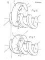
- the invention is illustrated on the basis of two rolling rings 5, 5 'in FIGS. 1 to 5, the inner top ring surface 7 (FIGS. 2 and 3) of which are delimited by two basic circles 8, 9 and 8', 9 ', which roll with their oblique sides 10, 11 on the flanks 13, 14 of the threads 2 of the spindle thread.
- the inner base circle 8, 9 or 8 ', 9' and the adjacent outer helix 15, 16 or 15 ', 16' of the flanks 13, 14 of the threads 2 are to be considered. on which the corresponding oblique side 10 or 11 of the rolling ring 5, 5 'rolls (Fig. 1, 3, 4, 5).
- the aim should now be for this distance to take the smallest possible value, i.e. a value between 0 and 15%, preferably a value between 2 and 8% of the radius of the base circle or circles of the rolling rings.
- the point A 'of the base circle 9' of the rolling ring 5 'in FIG. 5 initially appears to have the same distance from the screw line 16 of the spindle 1 as the point A of the ring 5 from the screw line 16 of the spindle 1 in FIG. 4.
- the distance of the point A 'from the point D' of the helix 16 'from the base circle 9' of the rolling ring 5 'in the axial direction of the spindle 1 in FIG. 5 must be taken into account and this distance as the crossing distance between the two crossing points A ', D' is substantially larger than the crossing distance between point A and point D of the outer helix 16 from the base circle 9 of the embodiment according to FIG. 4.
- the helix 16 ' is adjacent to the base circle 9' of the rolling ring 5 '.
- the smallest distance between the base circle 9 'and the helical line 16' is denoted in this case by a ', the points A' and D 'being the smallest distance, i.e. have the crossing distance.
- the distance between the two points A and D as those points which define the smallest distance a between the base circle 9 and the adjacent helical line 16 is here much smaller than the distance a 'in the embodiment according to FIG. 6 with the larger rolling ring 5 '.
- the crossing distance a or a 'according to the invention, as explained above, should be between 0 and 15%, preferably between 2 and 8% of the radius of the base circles 8 and 9 of the rolling rings.
- the conditions that apply to the trapezoidal cross section of the rolling ring 8 correspond to the conditions in the case of a pointed thread and corresponding design of the rolling ring.
- the rolling rings 5 can be designed as an inner ring of a rolling bearing or connected to the inner ring of such a bearing, the bearing outer rings forming parts of the nut body or being connected to the nut body.
- a plurality of rolling rings can be used which are arranged as individual rings in a nut housing or which form the parts of a common nut body which has a plurality of rings such as beads or ribs on its inside.
Landscapes
- Engineering & Computer Science (AREA)
- General Engineering & Computer Science (AREA)
- Mechanical Engineering (AREA)
- Rolling Contact Bearings (AREA)
- Transmission Devices (AREA)
Applications Claiming Priority (2)
| Application Number | Priority Date | Filing Date | Title |
|---|---|---|---|
| DE19843446723 DE3446723A1 (de) | 1984-12-21 | 1984-12-21 | Spindeltrieb mit einer gewindespindel und einem oder mehreren die spindel exzentrisch umgebenden waelzringen |
| DE3446723 | 1984-12-21 |
Publications (2)
| Publication Number | Publication Date |
|---|---|
| EP0185301A1 true EP0185301A1 (fr) | 1986-06-25 |
| EP0185301B1 EP0185301B1 (fr) | 1988-11-02 |
Family
ID=6253442
Family Applications (1)
| Application Number | Title | Priority Date | Filing Date |
|---|---|---|---|
| EP85115735A Expired EP0185301B1 (fr) | 1984-12-21 | 1985-12-10 | Entraînement par vis sans fin, avec une tige filetée et un ou plusieurs anneaux roulants entourant la tige excentriquement |
Country Status (2)
| Country | Link |
|---|---|
| EP (1) | EP0185301B1 (fr) |
| DE (2) | DE3446723A1 (fr) |
Cited By (1)
| Publication number | Priority date | Publication date | Assignee | Title |
|---|---|---|---|---|
| JP2018518641A (ja) * | 2015-05-14 | 2018-07-12 | フォンダツィオーネ・イスティトゥート・イタリアーノ・ディ・テクノロジャFondazione Istituto Italiano Di Tecnologia | 完全な転がり接触を有するねじおよびナットタイプのリニア駆動機構 |
Citations (9)
| Publication number | Priority date | Publication date | Assignee | Title |
|---|---|---|---|---|
| US2556572A (en) * | 1944-08-23 | 1951-06-12 | William A Brinkhurst | Screw feed |
| CH519124A (de) * | 1970-05-08 | 1972-02-15 | Wahlmark Systems | Schraubengetriebe |
| US3698258A (en) * | 1970-05-30 | 1972-10-17 | Robert Gartner | Screw drive |
| US3730016A (en) * | 1971-06-14 | 1973-05-01 | Continental Can Co | Friction drive differential screw |
| US3937089A (en) * | 1972-12-19 | 1976-02-10 | Robert Gartner | Screw drive |
| DE2725054A1 (de) * | 1977-06-03 | 1978-12-14 | Gaertner Robert | Schraubengetriebe |
| DE2839920A1 (de) * | 1978-09-14 | 1980-03-27 | Gaertner Robert | Schraubenantrieb |
| EP0034640A1 (fr) * | 1980-02-25 | 1981-09-02 | Robert Dr. Gärtner | Mécanisme à vis |
| DE3421467A1 (de) * | 1983-06-10 | 1984-12-13 | Seikosha Co., Ltd., Tokio/Tokyo | Schraubenspindel |
-
1984
- 1984-12-21 DE DE19843446723 patent/DE3446723A1/de not_active Withdrawn
-
1985
- 1985-12-10 EP EP85115735A patent/EP0185301B1/fr not_active Expired
- 1985-12-10 DE DE8585115735T patent/DE3566026D1/de not_active Expired
Patent Citations (9)
| Publication number | Priority date | Publication date | Assignee | Title |
|---|---|---|---|---|
| US2556572A (en) * | 1944-08-23 | 1951-06-12 | William A Brinkhurst | Screw feed |
| CH519124A (de) * | 1970-05-08 | 1972-02-15 | Wahlmark Systems | Schraubengetriebe |
| US3698258A (en) * | 1970-05-30 | 1972-10-17 | Robert Gartner | Screw drive |
| US3730016A (en) * | 1971-06-14 | 1973-05-01 | Continental Can Co | Friction drive differential screw |
| US3937089A (en) * | 1972-12-19 | 1976-02-10 | Robert Gartner | Screw drive |
| DE2725054A1 (de) * | 1977-06-03 | 1978-12-14 | Gaertner Robert | Schraubengetriebe |
| DE2839920A1 (de) * | 1978-09-14 | 1980-03-27 | Gaertner Robert | Schraubenantrieb |
| EP0034640A1 (fr) * | 1980-02-25 | 1981-09-02 | Robert Dr. Gärtner | Mécanisme à vis |
| DE3421467A1 (de) * | 1983-06-10 | 1984-12-13 | Seikosha Co., Ltd., Tokio/Tokyo | Schraubenspindel |
Non-Patent Citations (1)
| Title |
|---|
| HüTTE, 26. Auflage, Band 2, 1931, Berlin WILHELM ERNST & SOHN * Seiten 13,14,15 * * |
Cited By (1)
| Publication number | Priority date | Publication date | Assignee | Title |
|---|---|---|---|---|
| JP2018518641A (ja) * | 2015-05-14 | 2018-07-12 | フォンダツィオーネ・イスティトゥート・イタリアーノ・ディ・テクノロジャFondazione Istituto Italiano Di Tecnologia | 完全な転がり接触を有するねじおよびナットタイプのリニア駆動機構 |
Also Published As
| Publication number | Publication date |
|---|---|
| EP0185301B1 (fr) | 1988-11-02 |
| DE3446723A1 (de) | 1986-06-26 |
| DE3566026D1 (en) | 1988-12-08 |
Similar Documents
| Publication | Publication Date | Title |
|---|---|---|
| DE2320406C2 (de) | Planetenrollenschraube | |
| DE3241350C2 (de) | Vorrichtung zur Umwandlung einer Drehbewegung in eine Linearbewegung | |
| DE3739059A1 (de) | Vorrichtung zur umwandlung einer drehbewegung in eine axialbewegung | |
| AT212249B (de) | Kaltgezogener Draht mit von der Kreisform abweichendem Massivquerschnitt sowie Verfahren und Vorrichtung zu seiner Herstellung | |
| DE2355844A1 (de) | Schraubverbindung | |
| DE1750617A1 (de) | Befestigungsmittel und Verfahren zu seiner Herstellung | |
| AT210236B (de) | Gewindebohrer | |
| EP3976977A1 (fr) | Élément de liaison | |
| EP0408492B1 (fr) | Ecrou avec filetage | |
| DE102023100989A1 (de) | Positionierungsvorrichtung | |
| DE1221517B (de) | Schraubtrieb | |
| DE1216642B (de) | Rollenschraube | |
| DE1808328C3 (de) | Mutter für ein Kugelumlauf-Schraubenspindelgetriebe | |
| DE1301682B (de) | Schneckengetriebe | |
| EP0185301B1 (fr) | Entraînement par vis sans fin, avec une tige filetée et un ou plusieurs anneaux roulants entourant la tige excentriquement | |
| DE3204919C1 (de) | Kugelgewindetrieb | |
| DE102013209293B4 (de) | Verfahren zum Herstellen eines Planetenwälzgewindetriebes und Baukasten zur Durchführung des Verfahrens | |
| DE4302478C2 (de) | Gewindetrieb für Feineinstellungen | |
| DE102019104125B4 (de) | Kugelgewindetrieb mit Verdrehsicherung | |
| DE2351830C2 (de) | Kugelschraubgetriebe | |
| DE2031974C3 (de) | Kurzspiralgenuteter Gewindebohrer ohne Vorschneidstufe | |
| DE2548119C3 (de) | Schraubenspindelgetriebe | |
| DE4115756A1 (de) | Waelzschraubtrieb | |
| EP0178479B1 (fr) | Mécanisme à vis | |
| DE69207944T2 (de) | Schneckenrad zum Eingriff in eine Zahnstange |
Legal Events
| Date | Code | Title | Description |
|---|---|---|---|
| PUAI | Public reference made under article 153(3) epc to a published international application that has entered the european phase |
Free format text: ORIGINAL CODE: 0009012 |
|
| AK | Designated contracting states |
Kind code of ref document: A1 Designated state(s): CH DE FR GB LI SE |
|
| 17P | Request for examination filed |
Effective date: 19861104 |
|
| 17Q | First examination report despatched |
Effective date: 19871210 |
|
| GRAA | (expected) grant |
Free format text: ORIGINAL CODE: 0009210 |
|
| AK | Designated contracting states |
Kind code of ref document: B1 Designated state(s): CH DE FR GB LI SE |
|
| REF | Corresponds to: |
Ref document number: 3566026 Country of ref document: DE Date of ref document: 19881208 |
|
| ET | Fr: translation filed | ||
| GBT | Gb: translation of ep patent filed (gb section 77(6)(a)/1977) | ||
| PLBE | No opposition filed within time limit |
Free format text: ORIGINAL CODE: 0009261 |
|
| STAA | Information on the status of an ep patent application or granted ep patent |
Free format text: STATUS: NO OPPOSITION FILED WITHIN TIME LIMIT |
|
| 26N | No opposition filed | ||
| EAL | Se: european patent in force in sweden |
Ref document number: 85115735.4 |
|
| REG | Reference to a national code |
Ref country code: GB Ref legal event code: IF02 |
|
| PGFP | Annual fee paid to national office [announced via postgrant information from national office to epo] |
Ref country code: FR Payment date: 20031124 Year of fee payment: 19 |
|
| PGFP | Annual fee paid to national office [announced via postgrant information from national office to epo] |
Ref country code: SE Payment date: 20031128 Year of fee payment: 19 |
|
| PGFP | Annual fee paid to national office [announced via postgrant information from national office to epo] |
Ref country code: GB Payment date: 20031203 Year of fee payment: 19 |
|
| PGFP | Annual fee paid to national office [announced via postgrant information from national office to epo] |
Ref country code: CH Payment date: 20031211 Year of fee payment: 19 |
|
| PGFP | Annual fee paid to national office [announced via postgrant information from national office to epo] |
Ref country code: DE Payment date: 20040102 Year of fee payment: 19 |
|
| PG25 | Lapsed in a contracting state [announced via postgrant information from national office to epo] |
Ref country code: GB Free format text: LAPSE BECAUSE OF NON-PAYMENT OF DUE FEES Effective date: 20041210 |
|
| PG25 | Lapsed in a contracting state [announced via postgrant information from national office to epo] |
Ref country code: SE Free format text: LAPSE BECAUSE OF NON-PAYMENT OF DUE FEES Effective date: 20041211 |
|
| PG25 | Lapsed in a contracting state [announced via postgrant information from national office to epo] |
Ref country code: LI Free format text: LAPSE BECAUSE OF NON-PAYMENT OF DUE FEES Effective date: 20041231 Ref country code: CH Free format text: LAPSE BECAUSE OF NON-PAYMENT OF DUE FEES Effective date: 20041231 |
|
| PG25 | Lapsed in a contracting state [announced via postgrant information from national office to epo] |
Ref country code: DE Free format text: LAPSE BECAUSE OF NON-PAYMENT OF DUE FEES Effective date: 20050701 |
|
| EUG | Se: european patent has lapsed | ||
| GBPC | Gb: european patent ceased through non-payment of renewal fee |
Effective date: 20041210 |
|
| REG | Reference to a national code |
Ref country code: CH Ref legal event code: PL |
|
| PG25 | Lapsed in a contracting state [announced via postgrant information from national office to epo] |
Ref country code: FR Free format text: LAPSE BECAUSE OF NON-PAYMENT OF DUE FEES Effective date: 20050831 |
|
| REG | Reference to a national code |
Ref country code: FR Ref legal event code: ST |