EP0185308A1 - Brennstoffeinspritzsystem - Google Patents
Brennstoffeinspritzsystem Download PDFInfo
- Publication number
- EP0185308A1 EP0185308A1 EP19850115792 EP85115792A EP0185308A1 EP 0185308 A1 EP0185308 A1 EP 0185308A1 EP 19850115792 EP19850115792 EP 19850115792 EP 85115792 A EP85115792 A EP 85115792A EP 0185308 A1 EP0185308 A1 EP 0185308A1
- Authority
- EP
- European Patent Office
- Prior art keywords
- fuel
- injection
- cam
- pressure
- value
- Prior art date
- Legal status (The legal status is an assumption and is not a legal conclusion. Google has not performed a legal analysis and makes no representation as to the accuracy of the status listed.)
- Granted
Links
- 238000002347 injection Methods 0.000 title claims abstract description 110
- 239000007924 injection Substances 0.000 title claims abstract description 110
- 239000000446 fuel Substances 0.000 title claims abstract description 100
- 238000002485 combustion reaction Methods 0.000 claims abstract description 41
- 238000000034 method Methods 0.000 claims abstract description 12
- 238000009877 rendering Methods 0.000 abstract 1
- OKKJLVBELUTLKV-UHFFFAOYSA-N Methanol Chemical compound OC OKKJLVBELUTLKV-UHFFFAOYSA-N 0.000 description 9
- 238000000889 atomisation Methods 0.000 description 2
- 239000003638 chemical reducing agent Substances 0.000 description 2
- 230000000694 effects Effects 0.000 description 2
- 150000001298 alcohols Chemical class 0.000 description 1
- 239000000567 combustion gas Substances 0.000 description 1
- 239000003344 environmental pollutant Substances 0.000 description 1
- 231100000719 pollutant Toxicity 0.000 description 1
- 238000007789 sealing Methods 0.000 description 1
Images

Classifications
-
- F—MECHANICAL ENGINEERING; LIGHTING; HEATING; WEAPONS; BLASTING
- F02—COMBUSTION ENGINES; HOT-GAS OR COMBUSTION-PRODUCT ENGINE PLANTS
- F02M—SUPPLYING COMBUSTION ENGINES IN GENERAL WITH COMBUSTIBLE MIXTURES OR CONSTITUENTS THEREOF
- F02M45/00—Fuel-injection apparatus characterised by having a cyclic delivery of specific time/pressure or time/quantity relationship
- F02M45/02—Fuel-injection apparatus characterised by having a cyclic delivery of specific time/pressure or time/quantity relationship with each cyclic delivery being separated into two or more parts
- F02M45/04—Fuel-injection apparatus characterised by having a cyclic delivery of specific time/pressure or time/quantity relationship with each cyclic delivery being separated into two or more parts with a small initial part, e.g. initial part for partial load and initial and main part for full load
- F02M45/06—Pumps peculiar thereto
- F02M45/063—Delivery stroke of piston being divided into two or more parts, e.g. by using specially shaped cams
-
- F—MECHANICAL ENGINEERING; LIGHTING; HEATING; WEAPONS; BLASTING
- F02—COMBUSTION ENGINES; HOT-GAS OR COMBUSTION-PRODUCT ENGINE PLANTS
- F02M—SUPPLYING COMBUSTION ENGINES IN GENERAL WITH COMBUSTIBLE MIXTURES OR CONSTITUENTS THEREOF
- F02M45/00—Fuel-injection apparatus characterised by having a cyclic delivery of specific time/pressure or time/quantity relationship
- F02M45/02—Fuel-injection apparatus characterised by having a cyclic delivery of specific time/pressure or time/quantity relationship with each cyclic delivery being separated into two or more parts
- F02M45/04—Fuel-injection apparatus characterised by having a cyclic delivery of specific time/pressure or time/quantity relationship with each cyclic delivery being separated into two or more parts with a small initial part, e.g. initial part for partial load and initial and main part for full load
-
- F—MECHANICAL ENGINEERING; LIGHTING; HEATING; WEAPONS; BLASTING
- F02—COMBUSTION ENGINES; HOT-GAS OR COMBUSTION-PRODUCT ENGINE PLANTS
- F02M—SUPPLYING COMBUSTION ENGINES IN GENERAL WITH COMBUSTIBLE MIXTURES OR CONSTITUENTS THEREOF
- F02M45/00—Fuel-injection apparatus characterised by having a cyclic delivery of specific time/pressure or time/quantity relationship
- F02M45/12—Fuel-injection apparatus characterised by having a cyclic delivery of specific time/pressure or time/quantity relationship providing a continuous cyclic delivery with variable pressure
-
- F—MECHANICAL ENGINEERING; LIGHTING; HEATING; WEAPONS; BLASTING
- F02—COMBUSTION ENGINES; HOT-GAS OR COMBUSTION-PRODUCT ENGINE PLANTS
- F02B—INTERNAL-COMBUSTION PISTON ENGINES; COMBUSTION ENGINES IN GENERAL
- F02B2275/00—Other engines, components or details, not provided for in other groups of this subclass
- F02B2275/14—Direct injection into combustion chamber
-
- F—MECHANICAL ENGINEERING; LIGHTING; HEATING; WEAPONS; BLASTING
- F02—COMBUSTION ENGINES; HOT-GAS OR COMBUSTION-PRODUCT ENGINE PLANTS
- F02B—INTERNAL-COMBUSTION PISTON ENGINES; COMBUSTION ENGINES IN GENERAL
- F02B3/00—Engines characterised by air compression and subsequent fuel addition
- F02B3/06—Engines characterised by air compression and subsequent fuel addition with compression ignition
-
- Y—GENERAL TAGGING OF NEW TECHNOLOGICAL DEVELOPMENTS; GENERAL TAGGING OF CROSS-SECTIONAL TECHNOLOGIES SPANNING OVER SEVERAL SECTIONS OF THE IPC; TECHNICAL SUBJECTS COVERED BY FORMER USPC CROSS-REFERENCE ART COLLECTIONS [XRACs] AND DIGESTS
- Y02—TECHNOLOGIES OR APPLICATIONS FOR MITIGATION OR ADAPTATION AGAINST CLIMATE CHANGE
- Y02T—CLIMATE CHANGE MITIGATION TECHNOLOGIES RELATED TO TRANSPORTATION
- Y02T10/00—Road transport of goods or passengers
- Y02T10/10—Internal combustion engine [ICE] based vehicles
- Y02T10/12—Improving ICE efficiencies
Definitions
- the invention relates to a fuel injection system for injecting fuel into the combustion chamber of an internal combustion engine, in particular a diesel engine operating according to the direct injection method, consisting of an injection pump driven by the internal combustion engine with a camshaft and at least one injection valve associated with the injection pump with an axially guided nozzle needle, in the fuel supply of which is arranged a throttle which can be switched off at approximately full delivery pressure of the fuel, a reduced value of the maximum delivery pressure of the injection pump being present at the nozzle needle at the beginning of the injection process and lifting the nozzle needle.
- a fuel injection system for injecting fuel into the combustion chamber of an internal combustion engine, in particular a diesel engine operating according to the direct injection method, consisting of an injection pump driven by the internal combustion engine with a camshaft and at least one injection valve associated with the injection pump with an axially guided nozzle needle, in the fuel supply of which is arranged a throttle which can be switched off at approximately full delivery pressure of the fuel, a reduced value of the maximum delivery pressure of the injection pump being present at the
- a fuel injection system which, in a diesel engine operating according to the direct injection method, brings the fuel into the combustion chamber of the internal combustion engine in such a way that low-noise operation is achieved.
- a commercially available injection pump is provided with a specially equipped injection valve in this laid-open specification.
- This injection valve works with a pressure reducer, which in the first phase of combustion lowers the injection pressure made available by the injection pump to a much lower value.
- the mass flow of the fuel is additionally limited by a throttle to a fixed volume.
- This quantity of fuel which is limited in terms of both pressure and volume, is injected into the combustion chamber before the actual main quantity of fuel and ignites there. The main fuel quantity is then injected directly afterwards, bypassing the pressure reducer and the throttle, so that the fuel can be injected at full delivery pressure.
- the invention has for its object to develop a fuel injection system according to the preamble of claim 1 so that a soft and quiet combustion can be achieved with a simple structure and high functional reliability, in particular the use of ignitable fuels in the internal combustion engine should be favored.
- the pressure and the delivery rate of the fuel is predetermined by a certain, stepped shape of the cam of the camshaft of the injection pump in such a way that a small amount of fuel is always injected before the main amount, thereby ensuring ignition or soft combustion.
- the stepped cam first brings the fuel pressure to at least an average value at which the pre-injection takes place, and after a short pause, the entire main fuel quantity is injected into the combustion chamber at full delivery pressure.
- the fuel is fed into the injection valve via a throttle within the fuel supply, the throttle limiting the volume to a constant value during the pre-injection.
- the injection pressure begins to rise to its maximum value, all of the fuel can no longer reach the nozzle needle tip through the throttle, and a pressure builds up in the feed to the injection valve up to the maximum value of the pressure of the injection pump.
- This fuel injection system enables the internal combustion engine to run smoothly in a simple manner.
- This change can be produced in a particularly simple manner, for example by grinding, without additional parts and therefore inexpensively.
- the throttle restricts the amount of fuel injected during the pre-injection over the entire speed and load range of the internal combustion engine, so that the same small amount of fuel is injected even at full load. In the entire operating map of the internal combustion engine, the injection rate per degree crank angle remains constant during the pre-injection.
- the pressure relief valve is only opened when the main injection is used, and the fuel can reach the nozzle needle unhindered.
- the fuel injection system according to the invention is advantageously able to change the necessary glow plug temperature by means of the pre-injection lower by 100 ° and more. In this case, the combustion of the pre-injected fuel provides part of the energy required to ignite the fuel that does not ignite. The service life of the glow plug used is considerably increased.
- the pressure relief valve opens in a pressure range of 60 to 100 bar of the differential pressure at the throttle, a pressure of 70 bar in particular having proven to be expedient.
- the injection pump delivers the fuel through the throttle to the nozzle needle.
- an average or almost the maximum fuel pressure builds up in front of the throttle and is throttled by the throttle to a somewhat lower value in the injection valve when it is delivered.
- the small amount of fuel in the pre-injection passes the throttle and, with its pressure value reduced by the throttling effect, just lifts the nozzle needle.
- the pre-injection runs. D a still almost complete fuel pressure is applied, is safely achieved good atomization of the fuel.
- the pressure relief valve opens and the delivery pressure can act completely on the nozzle needle.
- a maximum delivery pressure of 250 bar is advisable.
- the stroke of the nozzle needle during the pre-injection is set at approximately 10% of the value of the main injection.
- An internal combustion engine not shown, which works according to the direct injection method for diesel engines, is provided with an injection pump 1.
- the injection pump 1 has a driven camshaft 2 and a control rod 3 that controls the fuel quantity.
- the camshaft 2 drives pump tappets to convey the fuel.
- a pump cylinder of the injection pump 1 is connected to the fuel supply 5 of an injection valve 6 via a constant pressure relief valve 33 and via a line 4.
- a throttle 7 and an overpressure valve 8 opening in the direction of flow of the fuel are arranged parallel to one another in the injection valve 6. Both the throttle 7 and the pressure relief valve 8 can also be arranged at a spatial distance from the injection valve 6.
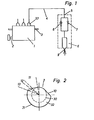
- FIG. 2 shows a cross section of the camshaft 2 of the injection pump 1, the cam contour 10 of a cam 32 being shown.
- This cam contour 10 is divided into three sections 11, 12, 13 during the elevation curve.
- the first section 11 starts from the base circle 30 of the cam contour 10 and leads to an initial stroke at which the injection of the fuel into the combustion chamber has just started.
- the next, second section 12 has no further increase in stroke, but runs almost on an arc around the center of the camshaft 2.
- it may be expedient that a slight increase in the elevation curve is realized in this second section 12, so that the Injection is continued continuously, but the pressure of the fuel does not continue to increase.
- the elevation curve is quickly raised to its maximum value 31, the main part of the injection taking place in this section 13.
- the slope of the elevation curve in the first section 11 is tangent to the base circle.
- the elevation curve in the third section 13 is shifted parallel to that in the first section 11 and thus corresponds to a tangent to a smaller base circle.
- FIG. 3 shows the injection valve 6 according to the invention, which has a fuel supply 5 at the upper end for supplying the fuel from the injection pump 1.
- the pressure relief valve 8 with a spring 14 and a sealing cone 15 is inserted directly below the fuel supply 5.
- a bore 16, which acts as a throttle 7, is arranged centrally in the pressure relief valve 8. It may also be expedient to provide the throttle 7 separately from the pressure relief valve 8 as a separate bore.
- the fuel is conducted via channels 17, 18, 19 and 20 to the nozzle needle seat 21 of a nozzle needle 22 at outlet openings 9.
- the nozzle needle 22 has a pressure shoulder 23 on which the fuel pressure acts counter to the force of a spring 24.
- the nozzle needle 22 is inserted pressure-tight in a nozzle insert 25, which in turn is screwed to a valve body 27 via an intermediate piece 26 with a sleeve 28. Any leakage oil that may leak can be discharged through a leakage oil connection 29.
- the camshaft 2 of the injection pump 1 actuates a pump tappet through the cam 10.
- the camshaft 2 rotates clockwise in the position shown in FIG. 2.
- the pump tappet initially moves on the base circle diameter of the cam 10 and thus reaches the first section 11 of the elevation curve. In this first section 11, the cam elevation rises tangentially.
- the B uel pressure thus begins to rise continuously and acts on the throttle 7 22 on the nozzle needle At a certain, at least average value of the pressure begins to open the nozzle needle 22, and the fuel is injected.
- the throttle 7 limits the amount of fuel, with a pressure difference across the throttle 7 arises. This small amount of fuel and the short period of time raise the nozzle needle only slightly so that good atomization is achieved.
- the throttle 7 also causes the pre-injected fuel quantity to remain largely constant over the entire operating map of the internal combustion engine.
- the stroke achieved initially remains constant over a range of preferably 15 to 20 ° crank angle of the internal combustion engine.
- the pilot injection breaks down again.
- the third section 13 of the elevation curve begins, in which the stroke is increased to the maximum value 31 of the elevation curve.
- the main injection of the fuel into the combustion chamber takes place in this area.
- the slope of the cam contour 10 is the same as that selected in the first section 11.
- the slope in the third section 13 may also be expedient for the slope in the third section 13 to be greater than in the first section 11.
- the pressure of the fuel rises rapidly to the maximum value as it passes through the third section 13, and it begins to build up a pressure difference at the throttle 7, since not the entire amount of fuel can pass the throttle 7.
- the nozzle idle 22 now opens completely, with the main injection of the internal combustion engine taking place.
- constant pressure relief valve 33 replaces the usual equal space relief valve and ensures that there is always a precisely defined relief pressure in the line 4 and in the injection valve 6 itself at the beginning of an injection process. For some applications, however, a constant pressure relief valve can also be sufficient if pressure is largely relieved completely.
- the pre-injection quantity of the fuel in front of the throttle 7 in the fuel supply 5 increases as a result of dynamic effects.
- the throttle 7 it is advantageously achieved that at low and high engine speeds, only a constant, small amount of fuel always comes into the combustion chamber for pre-injection, so that the injection rate per degree crank angle remains constantly small.
- the throttle 7 is bridged by the pressure relief valve 8, so that the direct, unthrottled path to the outlet opening 9 is free regardless of the speed or the load.
- the pressure curve of the fuel pressure ensures that a pre-injection takes place with a largely constant amount of fuel and at approximately constant pressure, whereby the fuel introduced during the main injection always finds optimal ignition conditions, the ignition delay is reduced and ultimately the engine run becomes even and calm.
- a glow ignition source such as internal combustion engines have which are operated with methanol
- the temperature of the glow ignition source is reduced by approximately 100 ° C. by means of such a pre-injection, which advantageously extends its service life.
- Pre-injection of this type also advantageously reduces pollutant emissions, in particular NO x .
Landscapes
- Engineering & Computer Science (AREA)
- Chemical & Material Sciences (AREA)
- Combustion & Propulsion (AREA)
- Mechanical Engineering (AREA)
- General Engineering & Computer Science (AREA)
- Fuel-Injection Apparatus (AREA)
- Materials For Photolithography (AREA)
Abstract
Description
- Die Erfindung bezieht sich auf ein Brennstoffeinspritzsystem zum Einspritzen von Brennstoff in den Brennraum einer Brennkraftmaschine, insbesondere einer nach dem Direkteinspritzverfahren arbeitenden Dieselmaschine, bestehend aus einer von der Brennkraftmaschine angetriebenen Einspritzpumpe mit einer Nockenwelle und zumindest einem der Einspritzpumpe zugeordneten Einspritzventil mit einer axial geführten Düsennadel, in dessen Brennstoffzuführung eine bei annähernd vollem Förderdruck des Brennstoffes abschaltbare Drossel angeordnet ist, wobei am Beginn des Einspritzvorganges an der Düsennadel ein verminderter Wert des maximalen Förderdruckes der Einspritzpumpe ansteht und die Düsennadel anhebt.
- Bei nach dem Direkteinspritzverfahren arbeitenden Dieselmotoren besteht seit jeher die Problematik der geräuschvollen Verbrennung. Durch plötzliche Entzündung des eingespritzten Brennstoffes im Brennraum der Brennkraftmaschine wird ein rascher Druckanstieg verursacht, der das unter dem Begriff °Nageln° bekannte Geräusch erzeugt. Es ist schon vielfach versucht worden, dem Dieselmotor durch bestimmte Einspritzverläufe, wie beispielsweise durch eine langsam ansteigende Einspritzmenge, eine geräuscharme und gleichmäßige Verbrennung aufzuzwingen. Bei der Verwendung von zündunwilligen Brennstoffen, wie beispielsweise Methanol oder andere Alkohole, ist eine gleichmäßige und mit langsamem Druckanstieg arbeitende Verbrennung noch schwieriger zu erreichen. Durch die Verwendung von Glühkerzen, die den eingespritzten Brennstoff rechtzeitig entzünden, soll ein gleichmäßiger Druckanstieg während der Verbrennung erzielt werden. Derartige Glühzündungsquellen müssen zur sicheren Wirkung mit hohen Temperaturen betrieben werden, was deren Lebensdauer erheblich einschränkt. Da sie zusätzlich auch den heißen Verbrennungsgasen ausgesetzt sind, wird ihre Lebensdauer noch weiter vermindert.
- Aus der DE-OS 19 50 144 ist eine Brennstoffeinspritzanlage bekannt, die bei einem nach dem Direkteinspritzverfahren arbeitenden Dieselmotor den Brennstoff in den Brennraum der Brennkraftmaschine derart einbringt, daß ein geräuscharmer Lauf erreicht wird. Dazu wird in dieser Offenlegungsschrift eine handelsübliche Einspritzpumpe mit einem besonders ausgestatteten Einspritzventil versehen. Dieses Einspritzventil arbeitet mit einem Druckminderer, der in der ersten Phase der Verbrennung den von der Einspritzpumpe zur Verfügung gestellten Einspritzdruck auf einen wesentlich niedrigeren Wert senkt. Der Massenstrom des Brennstoffes ist dabei zusätzlich von einer Drossel auf einen volumenmäßig festen Wert beschränkt. Diese sowohl druckmäßig als auch volumenmäßig begrenzte Brennstoffmenge wird vor der eigentlichen Hauptbrennstoffmenge in den Brennraum eingespritzt und zündet dort. Die Einspritzung der Hauptbrennstoffmenge erfolgt dann direkt anschließend, wobei der Druckminderer und die Drossel umgangen werden, so daß der Brennstoff mit vollem Förderdruck eingespritzt werden kann.
- Als nachteilig hat sich bei dieser Brennstoffeinspritzanlage herausgestellt, daß ein zusätzliches fehleranfälliges Druckminderventil zum Herabsetzen des Brennstoffdruckes vorgesehen werden muß. Dadurch wird eine Vielzahl von weiteren Teilen benötigt, wodurch sich der Aufbau der Brennstoffeinspritzanlage verkompliziert und verteuert.
- Der Erfindung liegt die Aufgabe zugrunde, ein Brennstoffeinspritzsystem gemäß dem Oberbegriff des Anspruchs 1 so weiterzubilden, daß bei einfachem Aufbau und hoher Funktionssicherheit eine weiche und ruhige Verbrennung erzielbar ist, wobei insbesondere die Verwendung zündunwilliger Brennstoffe in der Brennkraftmaschine begünstigt werden soll.
- Diese Aufgabe wird durch die kennzeichnenden Merkmale des Anspruchs 1 gelöst.
- Der Druck und die Fördermenge des Brennstoffes wird durch eine bestimmte, gestufte Formgebung des Nockens der Nockenwelle der Einspritzpumpe derart vorgegeben, daß immer eine kleine Menge Brennstoff vor der Hauptmenge eingespritzt wird und dadurch die Zündung bzw. die weiche Verbrennung sichergestellt ist. Zeitlich gesehen wird durch den gestuften Nocken zuerst der Brennstoffdruck auf zumindest einen mittleren-Wert gebracht, bei dem die Voreinspritzung abläuft, und nach einer kurzen Verharrungspause die gesamte Hauptbrennstoffmenge bei vollem Förderdruck in den Brennraum eingespritzt. Der Brennstoff wird dabei über eine Drossel innerhalb der Brennstoffzuführung in das Einspritzventil geleitet, wobei die Drossel während der Voreinspritzung das Volumen auf einen konstanten Wert begrenzt. Wenn der Einspritzdruck auf seinen Maximalwert anzusteigen beginnt, kann nicht mehr der gesamte Brennstoff durch die Drossel an die Düsennadelspitze gelangen, und in der Zuführung zum Einspritzventil baut sich ein Druck bis zum Maximalwert des Druckes der Einspritzpumpe auf.
- Gleichzeitig wächst die Druckdifferenz zwischen Ein- und Austritt der Drossel. Ab einem bestimmten Grenzwert dieses Differenzdruckes öffnet ein Uberdruckventil, und der Brennstoff kann von der Einspritzpumpe ohne die Drossel passieren zu müssen direkt auf die Düsennadel wirken, womit die Haupteinspritzung abläuft.
- Durch dieses erfindungsgemäße Brennstoffeinspritzsystem wird auf einfache Weise ein ruhiger Lauf der Brennkraftmaschine erreicht. Zur Erzeugung des zunächst auf zumindest einen mittleren Wert ansteigenden, dann zumeist etwas abfallenden und schließlich auf den Höchstwert ansteigenden Brennstoffdruckes ist in vorteilhafter Weise nur eine in den Erhebungskurven der Nocken geänderte nämlich gestufte Nockenwelle der Einspritzpumpe notwendig. Diese Änderung läßt sich auf besonders einfache Weise, beispielsweise durch Schleifen, ohne zusätzliche Teile und daher preisgünstig herstellen. Die Drossel beschränkt die während der Voreinspritzung eingespritzte Brennstoffmenge über den gesamten Drehzahl- und Lastbereich der Brennkraftmaschine, so daß auch im Vollastbereich die gleiche geringfügige Menge Brennstoff zur Einspritzung gelangt. Im gesamten Betriebskennfeld der Brennkraftmaschine bleibt so während der Voreinspritzung die Einspritzrate pro Grad Kurbelwinkel konstant klein. Erst mit dem Einsatz der Haupteinspritzung wird das überdruckventil geöffnet, und der Brennstoff kann ungehindert zur Düsennadel vordringen. Bei der Verwendung von zündunwilligen Brennstoffen, wie beispielsweise Methanol, ist das erfindungsgemäße Brennstoffeinspritzsystem in vorteilhafter Weise in der Lage, durch die Voreinspritzung die notwendige Glühkerzentemperatur um bis zum 100° und mehr abzusenken. Einen Teil der zur Entzündung des zündunwilligen Brennstoffes notwendigen Energie liefert in diesem Fall die Verbrennung des voreingespritzten Brennstoffes. Die Lebensdauer der verwendeten Glühkerze wird so erheblich gesteigert.
- In einer vorteilhaften Ausgestaltung der Erfindung öffnet das Überdruckventil in einem Druckbereich von 60 bis 100 bar des anstehenden Differenzdruckes an der Drossel, wobei sich insbesondere ein Druck von 70 bar als zweckmäßig erwiesen hat. Unterhalb dieses Differenzdruckwerts fördert die Einspritzpumpe den Brennstoff durch die Drossel bis zur Düsennadel. Während der Voreinspritzung baut sich zunächst vor der Drossel ein mittlerer oder nahezu der maximale Brennstoffdruck auf und wird von der Drossel bei Förderung auf einen etwas geringeren Wert im Einspritzventil gedrosselt. Die kleine Brennstoffmenge der Voreinspritzung passiert die Drossel und hebt mit ihrem um die Drosselwirkung verminderten Druckwert die Düsennadel gerade eben an. Die Voreinspritzung läuft ab. Da trotzdem der fast vollständige Brennstoffdruck anliegt, wird eine gute Zerstäubung des Brennstoffs sicher erreicht. Bei der Haupteinspritzung kann nicht der gesamte Brennstoff durch die Drossel gelangen, so daß sich zwischen dem Ein- und Auslaß der Drossel ein Differenzdruck aufbaut. Ab einem bestimmten Wert dieses Differenzdruckes, vorzugsweise bei 70 bar, öffnet das Überdruckventil, und der Förderdruck kann vollständig auf die Düsennadel wirken. Zweckmäßig ist hierbei ein maximaler Förderdruck von 250 bar. Der Hub der Düsennadel während der Voreinspritzung stellt sich in einer weiteren vorteilhaften Ausbildung der Erfindung bei etwa 10 % des Wertes der Haupteinspritzung ein.
- Weitere Merkmale und Vorteile der Erfindung ergeben sich aus den weiteren Ansprüchen, der nachfolgenden Beschreibung und der Zeichnung, die ein Ausführungsbeispiel der Erfindung schematisch darstellt. Es zeigt:
- Fig. 1 eine schematische Darstellung des erfindungsgemäßen Brennstoffeinspritzsystems;
- Fig. 2 einen Querschnitt durch eine erfindungsgemäße Nockenwelle der Einspritzpumpe in Höhe eines Nockens;
- Fig. 3 einen Längsschnitt durch ein erfindungsgemäßes Einspritzventil mit einem überdruckventil und einer Drossel.
- Eine nicht gezeigte Brennkraftmaschine, die nach dem Direkteinspritzverfahren für Dieselmotoren arbeitet, ist mit einer Einspritzpumpe 1 versehen. Die Einspritzpumpe 1 weist eine angetriebene Nockenwelle 2 und eine die Brennstoffmenge steuernde Regelstange 3 auf. Die Nockenwelle 2 treibt Pumpenstößel zur Förderung des Brennstoffes an. Ein Pumpenzylinder der Einspritzpumpe 1 ist über ein Gleichdruckentlastungsventil 33 und über eine Leitung 4 mit der Brennstoffzuführung 5 eines Einspritzventils 6 verbunden. Unmittelbar hinter der Brennstoffzuführung 5 sind in dem Einspritzventil 6 eine Drossel 7 und ein in Strömungsrichtung des Brennstoffes öffnendes Uberdruckventil 8 parallel zueinander angeordnet. Sowohl die Drossel 7 als auch das Überdruckventil 8 können auch in räumlicher Entfernung zum Einspritzventil 6 angeordnet sein. Um jedoch die Kompressibilitätseinflüsse des Brennstoffes möglichst klein zu halten, ist eine Anordnung möglichst nahe am Einspritzort vorteilhaft. In Strömungsrichtung des Brennstoffes hinter der Drossel 7 und dem Überdruckventil 8 sind Leitungen für den Brennstoff zu einer Austrittsöffnung 9 des Einspritzventils 6 vorgesehen, durch die der Brennstoff in den Brennraum der Brennkraftmaschine eintritt (Fig. 1).
- Fig. 2 zeigt einen Querschnitt der Nockenwelle 2 der Einspritzpumpe 1, wobei die Nockenkontur 10 eines Nockens 32 dargestellt ist. Diese Nockenkontur 10 ist während der Erhebungskurve in drei Abschnitte 11, 12, 13 aufgeteilt. Der erste Abschnitt 11 geht von dem Grundkreis 30 der Nockenkontur 10 aus und führt bis zu einem Anfangshub, bei dem die Einspritzung des Brennstoffes in den Brennraum gerade begonnen hat. Der nächste, zweite Abschnitt 12 weist keine weitere Hubsteigerung auf, sondern verläuft nahezu auf einem Kreisbogen um den Mittelpunkt der Nockenwelle 2. In manchen Fällen kann es zweckmäßig sein, daß in diesem zweiten Abschnitt 12 eine leichte Steigung der Erhebungskurve realsisiert wird, so daß die Einspritzung kontinuierlich fortgeführt wird, jedoch der Druck des Brennstoffes nicht weiter zunimmt. In einem dritten Abschnitt 13 wird die Erhebungskurve zügig auf ihren Maximalwert 31 angehoben, wobei in diesem Abschnitt 13 der Hauptteil der Einspritzung abläuft. Die Steigung der Erhebungskurve in dem ersten Abschnitt 11 ist tangentenförmig zum Grundkreis ausgebildet. Die Erhebungskurve im dritten Abschnitt 13 ist zu derjenigen im ersten Abschnitt 11 parallel verschoben und entspricht somit einer Tangente an einem kleineren Grundkreis.
- Fig. 3 zeigt das erfindungsgemäße Einspritzventil 6, das am oberen Ende eine Brennstoffzuführung 5 für die Zuführung des Brennstoffs von der Einspritzpumpe 1 aufweist. Direkt unterhalb der Brennstoffzuführung 5 ist das Überdruckventil 8 mit einer Feder 14 und einem dichtenden Konus 15 eingefügt. Zentrisch in dem Uberdruckventil 8 ist eine Bohrung 16 angeordnet, die als Drossel 7 wirkt. Es kann auch zweckmäßig sein, die Drossel 7 getrennt von dem Überdruckventil 8 als separate Bohrung vorzusehen. Der Brennstoff wird über Kanäle 17, 18, 19 und 20 bis zum Düsennadelsitz 21 einer Düsennadel 22 an Austrittsöffnungen 9 geführt. Die Düsennadel 22 weist eine Druckschulter 23 auf, auf die der Brennstoffdruck entgegen der Kraft einer Feder 24 wirkt. Die Düsennadel 22 ist dabei druckdicht in einem Düseneinsatz 25 eingesetzt, der wiederum über ein Zwischenstück 26 mit einer Hülse 28 an einen Ventilkörper 27 geschraubt ist. Durch einen Leckölanschluß 29 kann evtl..austretendes Lecköl abgeführt werden.
- -Bei dem erfindungsgemäßen Brennstoffeinspritzsystem betätigt die Nockenwelle 2 der Einspritzpumpe 1 durch den Nocken 10 einen PumpenstöBel. Die Nockenwelle 2 dreht sich dabei in der in Fig. 2 gezeigten Lage im Uhrzeigersinn. Der PumpenstöBel wandert zunächst auf dem Grundkreisdurchmesser des Nockens 10 und gelangt so auf den ersten Abschnitt 11 der Erhebungskurve. In diesem ersten Abschnitt 11 steigt die Nockenerhebung tangentenförmig an. Der Brennstoffdruck beginnt somit, kontinuierlich anzusteigen und wirkt über die Drossel 7 auf die Düsennadel 22. Bei einem bestimmten, zumindest mittleren Wert des Druckes beginnt die Düsennadel 22 zu öffnen, und der Brennstoff wird eingespritzt. Die Drossel 7 begrenzt dabei die Menge des Brennstoffs, wobei an der Drossel 7 eine Druckdifferenz entsteht. Durch diese geringe Brennstoffmenge und die kurze Zeitdauer wird die Düsennadel nur geringfügig angehoben, so daß eine gute Zerstäubung erreicht wird. Die Drossel 7 bewirkt ferner, daß die voreingespritzte Brennstoffmenge über das gesamte Betriebskennfeld der Brennkraftmaschine weitgehend konstant bleibt. In dem zweiten Abschnitt 12 der Erhebungskurve bleibt der erreichte Hub zunächst über einen Bereich von vorzugsweise 15 bis 20° Kurbelwinkel der Brennkraftmaschine konstant. Dadurch bricht die Voreinspritzung wieder zusammen. In manchen Fällen kann es jedoch auch zweckmäßig sein, in den Bereich 12 die Nockenkontur 10 mit einer leichten Steigung zu versehen, so daß der Druck im Brennstoff nicht weiter anwächst, jedoch die Brennstofförderung nicht unterbrochen wird. Am Ende des zweiten Abschnitts 12 beginnt der dritte Abschnitt 13 der Erhebungskurve, in dem der Hub auf den maximalen Wert 31 der Erhebungskurve gesteigert wird. In diesem Bereich findet die Haupteinspritzung des Brennstoffes in den Brennraum statt. Die Steigung der Nockenkontur 10 ist gleich der im ersten Abschnitt 11 gewählt. Zur Erzielung eines schneller anwachsenden Druckes kann es auch zweckdienlich sein, daß die Steigung im dritten Abschnitt 13 stärker ausgebildet ist als im ersten Abschnitt 11. Der Druck des Brennstoffs steigt während des Durchlaufens des dritten Abschnitts 13 schnell auf den Maximalwert an, und es beginnt sich an der Drossel 7 eine Druckdifferenz aufzubauen, da nicht die gesamte Brennstoffmenge die Drossel 7 passieren kann. Ab dem Grenzwert des Überdruckventils 8, der vorzugsweise bei 70 bar Differenzdruck liegt, öffnet dieses und der volle, ungedrosselte Brennstoffdruck kann auf die Düsennadel 22 wirken. Die Düsennidel 22 öffnet jetzt vollständig, wobei die Haupteinspritzung der Brennkraftmaschine erfolgt.
- Das in der Brennstoffleitung zum Einspritzventil 6 angeordnete Gleichdruckentlastungsventil 33 ersetzt das übliche Gleichraumentlastungsventil und stellt sicher, daß stets zu Anfang eines Einspritzvorganges ein genau definierter Entlastungsdruck in der Leitung 4 und im Einspritzventil 6 selbst herrscht. Für manche Anwendungsfälle kann jedoch auch ein Gleichraumentlastungsventil genügen, wenn weitgehend vollständig druckentlastet wird.
- Bei hohen Drehzahlen der Brennkraftmaschine steigt infolge dynamischer Effekte die Voreinspritzmenge des Brennstoffs vor der Drossel 7 in der Brennstoffzuführung 5 an. Durch die Drossel 7 wird in vorteilhafter Weise erreicht, daß bei niedrigen und hohen Drehzahlen der Brennkraftmaschine stets nur eine konstant gleiche, kleine Menge Brennstoff zur Voreinspritzung in den Brennraum gelangt, wodurch die Einspritzrate pro Grad Kurbelwinkel konstant klein bleibt. Während der Haupteinspritzung wird die Drossel 7 durch das Überdruckventil 8 überbrückt, so daß unabhängig von der Drehzahl oder der Last der direkte, ungedrosselte Weg zur Austrittsöffnung 9 frei ist. Durch diesen über die Zeit variierten Druckverlauf des Brennstoffdruckes wird sicher erreicht, daß eine Voreinspritzung mit weitgehend konstanter Brennstoffmenge und bei annähernd konstantem Druck stattfindet, wodurch der während der Haupteinspritzung eingebrachte Brennstoff stets optimale Zündbedingungen vorfindet, der Zündverzug verkleinert wird und letztendlich der Lauf der Bren kraftmaschine gleichmäßig und ruhig wird. Bei Brennkraftmaschinen mit einer Glühzündungsquelle, wie dies beispielsweise Brennkraftmaschinen aufweisen, die mit Methanol betrieben werden, wird durch eine derartige Voreinspritzung die Temperatur der Glühzündungsquelle um ca. 100°C herabgesetzt, wodurch sich deren Lebensdauer in vorteilhafter Weise verlängert. Auch wird durch eine derartige Voreinspritzung in vorteilhafter Weise die Schadstoffemission, insbesondere das NOx, verringert.
Claims (10)
dadurch gekennzeichnet, daß die Drossel (7) durch ein in der Brennstoffzuführung (5) angeordnetes und in Fließrichtung des Brennstoffes öffnendes Uberdruckventil (8) abschaltbar ist und daß die Nockenwelle (2) mit zumindest einem in der Erhebungskurve gestuften Nocken (32) versehen ist, wodurch der verminderte Wert des Förderdruckes erreichbar ist.
dadurch gekennzeichnet, daß im Vollastbereich der Brennkraftmaschine der Hub der Düsennadel (22) zu Beginn der Einspritzung in etwa 10% des Wertes am Ende der Einspritzung beträgt.
Priority Applications (1)
| Application Number | Priority Date | Filing Date | Title |
|---|---|---|---|
| AT85115792T ATE40446T1 (de) | 1984-12-15 | 1985-12-11 | Brennstoffeinspritzsystem. |
Applications Claiming Priority (2)
| Application Number | Priority Date | Filing Date | Title |
|---|---|---|---|
| DE3445825 | 1984-12-15 | ||
| DE19843445825 DE3445825A1 (de) | 1984-12-15 | 1984-12-15 | Brennstoffeinspritzsystem |
Publications (2)
| Publication Number | Publication Date |
|---|---|
| EP0185308A1 true EP0185308A1 (de) | 1986-06-25 |
| EP0185308B1 EP0185308B1 (de) | 1989-01-25 |
Family
ID=6252884
Family Applications (1)
| Application Number | Title | Priority Date | Filing Date |
|---|---|---|---|
| EP85115792A Expired EP0185308B1 (de) | 1984-12-15 | 1985-12-11 | Brennstoffeinspritzsystem |
Country Status (3)
| Country | Link |
|---|---|
| EP (1) | EP0185308B1 (de) |
| AT (1) | ATE40446T1 (de) |
| DE (2) | DE3445825A1 (de) |
Cited By (3)
| Publication number | Priority date | Publication date | Assignee | Title |
|---|---|---|---|---|
| EP0357247A1 (de) * | 1988-09-01 | 1990-03-07 | LUCAS INDUSTRIES public limited company | Brennstoffeinspritzsystem |
| WO1998023858A1 (de) * | 1996-11-25 | 1998-06-04 | Robert Bosch Gmbh | Kraftstoffeinspritzsystem |
| RU2196246C2 (ru) * | 1997-04-25 | 2003-01-10 | Роберт Бош Гмбх | Система впрыскивания топлива |
Families Citing this family (1)
| Publication number | Priority date | Publication date | Assignee | Title |
|---|---|---|---|---|
| RU2204727C2 (ru) * | 2000-08-11 | 2003-05-20 | Закрытое акционерное общество "СТИЛЬконцепт" | Способ работы многоцилиндрового четырехтактного двигателя внутреннего сгорания |
Citations (5)
| Publication number | Priority date | Publication date | Assignee | Title |
|---|---|---|---|---|
| GB401879A (en) * | 1931-11-14 | 1933-11-23 | Bosch Robert | Improvements in fuel injection devices for internal combustion engines |
| FR960760A (de) * | 1943-01-19 | 1950-04-25 | ||
| DE1476247A1 (de) * | 1964-10-26 | 1969-08-28 | Ricardo & Co Engineers | Kraftstoffeinspritzvorrichtung fuer mit Kraftstoffeinspritzung und Kompressionszuendung arbeitende Brennkraftmaschinen |
| FR2193421A5 (de) * | 1972-07-18 | 1974-02-15 | Bosch Gmbh Robert | |
| US4165838A (en) * | 1976-02-20 | 1979-08-28 | Diesel Kiki, Co., Ltd. | Fuel injection nozzle |
Family Cites Families (5)
| Publication number | Priority date | Publication date | Assignee | Title |
|---|---|---|---|---|
| CH165935A (de) * | 1931-11-14 | 1933-12-15 | Bosch Robert Ag | Einspritzeinrichtung für Brennkraftmaschinen. |
| DE715751C (de) * | 1936-02-18 | 1942-01-06 | Bosch Gmbh Robert | Brennstoffeinspritzanlage fuer Brennkraftmaschinen |
| DE763377C (de) * | 1943-01-19 | 1952-05-26 | Bosch Gmbh Robert | Kraftstoffeinspritzanlage fuer Brennkraftmaschinen |
| DE1192874B (de) * | 1962-05-09 | 1965-05-13 | Ricardo & Co Engineers | Brennstoffeinspritzeinrichtung |
| BR7907420A (pt) * | 1979-11-14 | 1981-05-19 | A Domschke | Adequacao de motores diesel para uso de metanol como combustivel |
-
1984
- 1984-12-15 DE DE19843445825 patent/DE3445825A1/de not_active Withdrawn
-
1985
- 1985-12-11 DE DE8585115792T patent/DE3567939D1/de not_active Expired
- 1985-12-11 EP EP85115792A patent/EP0185308B1/de not_active Expired
- 1985-12-11 AT AT85115792T patent/ATE40446T1/de not_active IP Right Cessation
Patent Citations (5)
| Publication number | Priority date | Publication date | Assignee | Title |
|---|---|---|---|---|
| GB401879A (en) * | 1931-11-14 | 1933-11-23 | Bosch Robert | Improvements in fuel injection devices for internal combustion engines |
| FR960760A (de) * | 1943-01-19 | 1950-04-25 | ||
| DE1476247A1 (de) * | 1964-10-26 | 1969-08-28 | Ricardo & Co Engineers | Kraftstoffeinspritzvorrichtung fuer mit Kraftstoffeinspritzung und Kompressionszuendung arbeitende Brennkraftmaschinen |
| FR2193421A5 (de) * | 1972-07-18 | 1974-02-15 | Bosch Gmbh Robert | |
| US4165838A (en) * | 1976-02-20 | 1979-08-28 | Diesel Kiki, Co., Ltd. | Fuel injection nozzle |
Cited By (5)
| Publication number | Priority date | Publication date | Assignee | Title |
|---|---|---|---|---|
| EP0357247A1 (de) * | 1988-09-01 | 1990-03-07 | LUCAS INDUSTRIES public limited company | Brennstoffeinspritzsystem |
| WO1998023858A1 (de) * | 1996-11-25 | 1998-06-04 | Robert Bosch Gmbh | Kraftstoffeinspritzsystem |
| RU2177559C2 (ru) * | 1996-11-25 | 2001-12-27 | Роберт Бош Гмбх | Система впрыскивания топлива |
| CN1079495C (zh) * | 1996-11-25 | 2002-02-20 | 罗伯特·博施有限公司 | 喷油系统 |
| RU2196246C2 (ru) * | 1997-04-25 | 2003-01-10 | Роберт Бош Гмбх | Система впрыскивания топлива |
Also Published As
| Publication number | Publication date |
|---|---|
| DE3445825A1 (de) | 1986-06-19 |
| EP0185308B1 (de) | 1989-01-25 |
| ATE40446T1 (de) | 1989-02-15 |
| DE3567939D1 (en) | 1989-03-02 |
Similar Documents
| Publication | Publication Date | Title |
|---|---|---|
| EP0116168B1 (de) | Kraftstoffeinspritzpumpe | |
| DE2742466A1 (de) | Pumpe-duese fuer luftverdichtende einspritzbrennkraftmaschinen | |
| DE4445586A1 (de) | Verfahren zur Reduzierung des Kraftstoffdruckes in einer Kraftstoffeinspritzeinrichtung | |
| DE3330772A1 (de) | Kraftstoffeinspritzeinrichtung | |
| EP1458970B1 (de) | Kraftstoffeinspritzeinrichtung für eine brennkraftmaschine | |
| DE19545162B4 (de) | Brennstoffeinspritzvorrichtung mit federvorgespanntem Steuerventil | |
| EP1045983B1 (de) | Kraftstoffeinspritzventil für brennkraftmaschinen | |
| DE60000255T2 (de) | Speicherkraftstoffeinspritzvorrichtung | |
| DE4211651B4 (de) | Kraftstoffeinspritzeinrichtung, insbesondere Pumpedüse für Brennkraftmaschinen | |
| DE2252769A1 (de) | Einspritzduese fuer fluessigen kraftstoff | |
| EP0185308B1 (de) | Brennstoffeinspritzsystem | |
| EP0502315A1 (de) | Kraftstoffeinspritzpumpe für Brennkraftmaschinen | |
| DE10141679A1 (de) | Kraftstoffeinspritzeinrichtung für eine Brennkraftmaschine | |
| DE2658833C2 (de) | ||
| DE19942291A1 (de) | Kraftstoffeinspritzventil für eine Brennkraftmaschine | |
| DE102018217723A1 (de) | Kraftstoffinjektor, Verfahren zum Betreiben eines Kraftstoffinjektors | |
| DE19618650A1 (de) | Kraftstoffeinspritzventil für Brennkraftmaschinen | |
| DE3807965A1 (de) | Pumpeduese | |
| DE3135877A1 (de) | Kraftstoffeinspritzpumpe | |
| DE2726300A1 (de) | Kraftstoffeinspritzduese | |
| EP0267421B1 (de) | Kraftstoff-Einspritzdüse für Brennkraftmaschinen | |
| DE3032735A1 (de) | Verfahren und kraftstoffeinspritzduese zur geteuerten kraftstoffeinspritzung bei brennkraftmaschinen | |
| WO2001018388A1 (de) | Kraftstoffeinspritzventil für brennkraftmaschinen | |
| DE3802136A1 (de) | Pumpeduese, insbesondere fuer direkt einspritzende diesel-brennkraftmaschinen | |
| DE19611884A1 (de) | Kraftstoffeinspritzventil für Brennkraftmaschinen |
Legal Events
| Date | Code | Title | Description |
|---|---|---|---|
| PUAI | Public reference made under article 153(3) epc to a published international application that has entered the european phase |
Free format text: ORIGINAL CODE: 0009012 |
|
| AK | Designated contracting states |
Kind code of ref document: A1 Designated state(s): AT DE FR GB IT NL |
|
| 17P | Request for examination filed |
Effective date: 19860514 |
|
| 17Q | First examination report despatched |
Effective date: 19870123 |
|
| GRAA | (expected) grant |
Free format text: ORIGINAL CODE: 0009210 |
|
| AK | Designated contracting states |
Kind code of ref document: B1 Designated state(s): AT DE FR GB IT NL |
|
| PG25 | Lapsed in a contracting state [announced via postgrant information from national office to epo] |
Ref country code: NL Effective date: 19890125 Ref country code: IT Free format text: LAPSE BECAUSE OF FAILURE TO SUBMIT A TRANSLATION OF THE DESCRIPTION OR TO PAY THE FEE WITHIN THE PRESCRIBED TIME-LIMIT;WARNING: LAPSES OF ITALIAN PATENTS WITH EFFECTIVE DATE BEFORE 2007 MAY HAVE OCCURRED AT ANY TIME BEFORE 2007. THE CORRECT EFFECTIVE DATE MAY BE DIFFERENT FROM THE ONE RECORDED. Effective date: 19890125 Ref country code: GB Free format text: LAPSE BECAUSE OF NON-PAYMENT OF DUE FEES Effective date: 19890125 Ref country code: FR Free format text: THE PATENT HAS BEEN ANNULLED BY A DECISION OF A NATIONAL AUTHORITY Effective date: 19890125 |
|
| REF | Corresponds to: |
Ref document number: 40446 Country of ref document: AT Date of ref document: 19890215 Kind code of ref document: T |
|
| REF | Corresponds to: |
Ref document number: 3567939 Country of ref document: DE Date of ref document: 19890302 |
|
| EN | Fr: translation not filed | ||
| NLV1 | Nl: lapsed or annulled due to failure to fulfill the requirements of art. 29p and 29m of the patents act | ||
| GBV | Gb: ep patent (uk) treated as always having been void in accordance with gb section 77(7)/1977 [no translation filed] | ||
| PLBE | No opposition filed within time limit |
Free format text: ORIGINAL CODE: 0009261 |
|
| STAA | Information on the status of an ep patent application or granted ep patent |
Free format text: STATUS: NO OPPOSITION FILED WITHIN TIME LIMIT |
|
| PG25 | Lapsed in a contracting state [announced via postgrant information from national office to epo] |
Ref country code: AT Effective date: 19891211 |
|
| 26N | No opposition filed | ||
| PGFP | Annual fee paid to national office [announced via postgrant information from national office to epo] |
Ref country code: DE Payment date: 19920107 Year of fee payment: 7 |
|
| PG25 | Lapsed in a contracting state [announced via postgrant information from national office to epo] |
Ref country code: DE Effective date: 19930901 |