EP0185336A2 - Dispositif d'étanchéité pour articulations de chaînes de véhicules à chenilles - Google Patents
Dispositif d'étanchéité pour articulations de chaînes de véhicules à chenilles Download PDFInfo
- Publication number
- EP0185336A2 EP0185336A2 EP85115981A EP85115981A EP0185336A2 EP 0185336 A2 EP0185336 A2 EP 0185336A2 EP 85115981 A EP85115981 A EP 85115981A EP 85115981 A EP85115981 A EP 85115981A EP 0185336 A2 EP0185336 A2 EP 0185336A2
- Authority
- EP
- European Patent Office
- Prior art keywords
- sealing
- recess
- chain
- sleeve
- sealing body
- Prior art date
- Legal status (The legal status is an assumption and is not a legal conclusion. Google has not performed a legal analysis and makes no representation as to the accuracy of the status listed.)
- Withdrawn
Links
- 238000007789 sealing Methods 0.000 title claims abstract description 154
- 125000006850 spacer group Chemical group 0.000 claims abstract description 20
- 230000003068 static effect Effects 0.000 claims abstract description 7
- 230000002093 peripheral effect Effects 0.000 claims description 5
- 239000000853 adhesive Substances 0.000 claims description 2
- 230000001070 adhesive effect Effects 0.000 claims description 2
- 238000007373 indentation Methods 0.000 abstract 1
- 239000002184 metal Substances 0.000 description 3
- 230000000694 effects Effects 0.000 description 2
- 239000000463 material Substances 0.000 description 2
- 239000004033 plastic Substances 0.000 description 2
- 229920003023 plastic Polymers 0.000 description 2
- 230000007704 transition Effects 0.000 description 2
- 239000011324 bead Substances 0.000 description 1
- 230000003139 buffering effect Effects 0.000 description 1
- 238000006073 displacement reaction Methods 0.000 description 1
- 229920001971 elastomer Polymers 0.000 description 1
- 239000000806 elastomer Substances 0.000 description 1
- 238000009434 installation Methods 0.000 description 1
- 239000000314 lubricant Substances 0.000 description 1
- 238000004519 manufacturing process Methods 0.000 description 1
- 229920002635 polyurethane Polymers 0.000 description 1
- 239000004814 polyurethane Substances 0.000 description 1
- 238000000926 separation method Methods 0.000 description 1
- 239000007787 solid Substances 0.000 description 1
Images


Classifications
-
- B—PERFORMING OPERATIONS; TRANSPORTING
- B62—LAND VEHICLES FOR TRAVELLING OTHERWISE THAN ON RAILS
- B62D—MOTOR VEHICLES; TRAILERS
- B62D55/00—Endless track vehicles
- B62D55/08—Endless track units; Parts thereof
- B62D55/088—Endless track units; Parts thereof with means to exclude or remove foreign matter, e.g. sealing means, self-cleaning track links or sprockets, deflector plates or scrapers
- B62D55/0887—Track-articulation sealings against dust, water, mud or the like
Definitions
- the invention relates to a sealing arrangement for track chain joints on tracked vehicles, in which four chain links arranged in pairs, overlapping in pairs, as well as a chain sleeve firmly connecting the axially inner link ends in the overlap area and a coaxial chain pin firmly connecting the chain links axially outside in the overlap area form a chain link that can be lubricated from a bore in the bolt which can be filled with lubricant, via a radial bore in the bolt, with each tab in the overlap area having a circular cylindrical recess on the inside for receiving a seal and a rigid spacer ring sitting on the bolt end protruding from the sleeve, the in a base surface of the recess lying in a radial plane is opposite an end surface of the chain sleeve which is normally in a parallel plane and adjacent to the recess and two overlapping Tabs form an annular gap, which radially opens the cavity bounded by the depression and the axially opposite end face; with an annular sealing body of
- the invention is therefore based on the object of providing a sealing arrangement, the use of which, with inevitable wear of the ring, which keeps the sleeve end face and the recess base area at a distance, does not lead to an early leakage as the wear of the spacer ring progresses.
- the invention is based on the basic idea that the dynamic as well as the static sealing of the chain link is no longer carried out axially, but purely radially, in order to leave the radial effectiveness unaffected despite the wear-related axial change in the sealing arrangement.
- the object on which the invention is based is achieved according to the invention in that the sealing body forms an exclusively radially sealing, axially movable, tiltable unit consisting of a rigid supporting part and at least one elastic sealing part and with axial play between the annular base of the depression and the annular base of an in the countersunk end face of the chain sleeve, which receives the dynamically sealing leg of the sealing body, is arranged with two radially opposite inner surfaces; and that the support part of the sealing body touches one of the two inner surfaces of the annular groove essentially only along a circular line, while at an approximately radially opposite location of the sealing body, the dynamically sealing sealing part acts on the other of the two inner surfaces; the statically sealing leg of the sealing body engages with the statically sealing sealing part on the cylindrical circumferential surface of the recess.
- the static and dynamic sealing takes place via boundary surfaces which are normally coaxial with respect to the axis of the hinge pin and whose axially parallel displacement does not in the least impair the radial sealing. If the spacer ring wears at the end, the axial clearance of the sealing body assigned to the axially opposite spacer ring is increased, but no separation of the sealing body from articulated surfaces in the area of the sealing surfaces is brought about.
- the annular groove in the chain sleeve is arranged radially outside the spacer ring and touches or acts on the Support and the sealing part of the sealing body with its dynamically sealing leg, the radially inner or outer of the two inner surfaces of the annular groove.
- the supporting part of the sealing body has a J-shaped or approximately U-shaped cross-sectional profile, its axially inner end having a curvature or angled portion that the axially inner end of the dynamically sealing sealing part has on its axially inner one Side supports.
- the dynamically sealing sealing part of the sealing body is advantageously reinforced.
- statically sealing part of the sealing body of the second embodiment where the z. .B. U-shaped profiled support part of the sealing body has at its axially outer end a bend which engages in the axially outer, radially inner corner of the statically sealing sealing part.
- the statically sealing sealing part of the sealing body is provided with projections distributed over its circumference axially outwards, which face the circular base surface of the depression.
- the sealing body receives a stop axially on one side, which allows a flow of radially displaced air.
- the supporting part of the sealing body has two circumferential, at least radially open grooves for receiving one O-ring each as sealing parts of the sealing body, which seal dynamically or statically. This embodiment is particularly easy to manufacture.
- the support and. the sealing part of the sealing body made of metal or an elastomeric plastic material, which have the required rigidity or low wear.
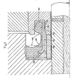
- a sealing body is intended and suitable for installation in an annular cavity 10, which approximately corresponds to a circular-cylindrical recess 12 in the axially inner end face 14 of the axially outer end 16 of a chain link 18, which press-fit on one end 20 of a chain pin 22 stuck, which protrudes with its end 20 from an end 24 of a chain sleeve 26, in which the bolt rotates with a sliding fit.
- the sleeve end 24 itself sits tightly on the axially inner end 28 of another chain link 30, which has an axially outer end face 32 which forms with the end face 14 an annular gap 34 opening into the depression 12 and thus into the cavity 10.
- the depression 12 is delimited axially outwardly by a flat annular base surface 36, radially outwardly by an annular circumferential surface 40 which is coaxial with respect to the axis 38 of the bolt 22 and radially inwardly by the bolt itself.
- the cavity 10 which is slightly smaller than this due to the engagement of the sleeve end 24 in the recess 12, is also through the base 36 and the peripheral surface 40, but also through the axially outer end face 42 of the sleeve end already in the recess and through one limited circular cylindrical spacer ring 44 which, when the tab end 28 and the tab end 16 are pressed onto the sleeve end 24 or the pin end 20, sets a defined vertical distance between the surfaces 36 and 42 lying in parallel planes which are radial with respect to the pin axis 38.
- annular groove 50 Perpendicular to its end face 42, an annular groove 50 with two concentric inner surfaces 52 and 54 is machined into the sleeve end 24 with respect to the pin axis 38 so that the the radially inner inner surface 54 has a larger diameter than the outer circumference of the spacer ring 44.
- annular sealing body 56 is present, the cross-sectional profile drawn in FIG. 1 is similar to a booted skate.
- This sealing body 56 consists of a rigid support member 58 in the form of a J-shaped metal ring and an elastic sealing member 60 made of an elastomer such as polyurethane.
- the sealing body 56 has two legs which form a right-angled transition to form its L-shaped profile, of which the radially extending leg 62 is formed exclusively by the sealing part 60, while the axially extending leg 64 is formed both by the sealing part 60 and by the supporting part 58 is formed, which reinforces the portion of the sealing part 60 which is due to the axial leg, in that its circular cylindrical section 66 on the radial inside of the sealing body 56 and its axially inner section 68 with an approximately semicircular profile are embedded in the sealing part 60 such that they merge flush into this and form part of the surface of the sealing body 56 instead of the sealing part.
- the radial leg 62 of the sealing body 56 has a plurality of projections 72, which are distributed uniformly over its circumference and extend axially outwards, from the annular base surface 36 of the recess 12 have an axial distance, which also applies to the support section 68 with respect to the base 49 of the annular groove 50.
- the sealing body 56 therefore has scope in both opposite axial directions.
- this inner surface has an axial orientation outwardly tapered conical section 76 which smoothly merges at the circular line 74 into an axially inwardly extending cylindrical section 78 of the radially inner inner surface 54.
- the circular line 74 is approximately radially opposite the dynamic sealing lip 70, which touches the circular-cylindrical, radially outer inner surface 52 of the annular groove 50 such that the free end of the curved supporting part section 68 does not touch this inner surface when the axial leg 64 of the sealing body 56 on its sealing lip 70 and the previously designated point 73 of its support member 58 is elastically clamped by the inner surfaces 52 and 54 of the annular groove 50, but along the circular line 74 there is, so to speak, a metallic contact between the sealing body and the chain sleeve 26.
- end-face wear of the spacer ring 44 on the axially opposite side of the chain link which is to be considered as a mirror image of FIG.
- the base surface 49 of the annular groove 50 moves away from the curved supporting part section 68, where the location 73 has the dynamic sealing lip 70 and / Move the transition of the support sections 66 and 68 into each other relatively axially outwards towards the edges of the annular groove 50.
- the support member 58 slides out of the circular line 74 axially outward via the conical inner surface section 76 when the chain sleeve 26 moves to the right with the fixed link plate 30 in FIG. 1.
- the sealing body 156 differs from the sealing body 56 in that its mainly circular cylindrical section 166, with its axially outer end already belonging to the radial leg 162, is bent at right angles into the sealing part 160, so that the supporting part 158 is firmly anchored there , and when its axially front end instead of the curved supporting part section 68 forms a radially inwardly projecting bead 180, which is flush with an axially inner, planar end face 182 of the sealing part 160 and touches the radially inner inner surface 54 of the annular groove 50 again along a circular line 174 .
- the sealing body 156 is similar to the sealing body 56.
- the sealing body 256 consists of a flat, L-shaped profiled, annular support part 258, the axial section of which engages in the annular groove 50 268 has a radially outwardly open rectangular groove 284 which receives an O-ring 286 as a dynamic sealing part of the sealing body, which lies flat against the radially outer inner surface 52 of the annular groove 50; and from a second, static sealing part in the form of a larger O-ring 288, which is seated in a right-angled corner recess 290 and protrudes both radially outside and axially outside over the supporting part 258, which in turn results in an interference fit of the O-ring 288 in the Circumferential surface 40 of the recess 12 results.
- the sealing body 258 does not touch the base 49 of the annular groove 50 and the base 36 of the recess 12. Axially on the inside there is mutual contact between the radially inner inner surface 54 of the annular groove 50 and the axial leg 268 of the supporting part 258 via a radially inwardly projecting rounding 292 which is approximately radially opposite the O-ring 286.
- a groove corresponding to the groove 284 could be provided. If necessary, however, the axial buffering effect of the O-ring 288 would be lost.
Landscapes
- Engineering & Computer Science (AREA)
- Chemical & Material Sciences (AREA)
- Combustion & Propulsion (AREA)
- Transportation (AREA)
- Mechanical Engineering (AREA)
- Sealing Devices (AREA)
Applications Claiming Priority (2)
| Application Number | Priority Date | Filing Date | Title |
|---|---|---|---|
| DE3446070 | 1984-12-18 | ||
| DE19843446070 DE3446070A1 (de) | 1984-12-18 | 1984-12-18 | Dichtungsanordnung fuer spurkettengelenke von kettenfahrzeugen |
Publications (2)
| Publication Number | Publication Date |
|---|---|
| EP0185336A2 true EP0185336A2 (fr) | 1986-06-25 |
| EP0185336A3 EP0185336A3 (fr) | 1987-09-09 |
Family
ID=6253045
Family Applications (1)
| Application Number | Title | Priority Date | Filing Date |
|---|---|---|---|
| EP85115981A Withdrawn EP0185336A3 (fr) | 1984-12-18 | 1985-12-14 | Dispositif d'étanchéité pour articulations de chaínes de véhicules à chenilles |
Country Status (2)
| Country | Link |
|---|---|
| EP (1) | EP0185336A3 (fr) |
| DE (1) | DE3446070A1 (fr) |
Cited By (2)
| Publication number | Priority date | Publication date | Assignee | Title |
|---|---|---|---|---|
| US8113597B2 (en) * | 2007-01-30 | 2012-02-14 | Berco S.P.A. | Track joint seal system |
| WO2012087799A1 (fr) * | 2010-12-23 | 2012-06-28 | Caterpillar Inc. | Ensemble d'étanchéité |
Family Cites Families (3)
| Publication number | Priority date | Publication date | Assignee | Title |
|---|---|---|---|---|
| US3437385A (en) * | 1967-01-24 | 1969-04-08 | Int Harvester Co | Track joint having floating seal |
| US3578343A (en) * | 1969-04-24 | 1971-05-11 | Koppers Co Inc | Annular shoulder assembly for a rotating seal |
| DE3321152C2 (de) * | 1983-06-11 | 1986-07-24 | Prädifa Präzisions-Dichtungs-Fabrik GmbH, 7120 Bietigheim-Bissingen | Dichtung für Spurkettengelenke von Kettenfahrzeugen |
-
1984
- 1984-12-18 DE DE19843446070 patent/DE3446070A1/de not_active Withdrawn
-
1985
- 1985-12-14 EP EP85115981A patent/EP0185336A3/fr not_active Withdrawn
Cited By (4)
| Publication number | Priority date | Publication date | Assignee | Title |
|---|---|---|---|---|
| US8113597B2 (en) * | 2007-01-30 | 2012-02-14 | Berco S.P.A. | Track joint seal system |
| WO2012087799A1 (fr) * | 2010-12-23 | 2012-06-28 | Caterpillar Inc. | Ensemble d'étanchéité |
| JP2014505620A (ja) * | 2010-12-23 | 2014-03-06 | キャタピラー インコーポレイテッド | シール組立体 |
| US8876226B2 (en) | 2010-12-23 | 2014-11-04 | Caterpillar Inc. | Seal assembly |
Also Published As
| Publication number | Publication date |
|---|---|
| EP0185336A3 (fr) | 1987-09-09 |
| DE3446070A1 (de) | 1986-06-19 |
Similar Documents
| Publication | Publication Date | Title |
|---|---|---|
| DE2756403B2 (de) | Dichtung | |
| DE4042201C1 (fr) | ||
| DE102009058216B4 (de) | Dichtungsanordnung und Gelenk einer Kette mit der Dichtungsanordnung | |
| DE102004031302A1 (de) | Ringscheibe für ein Gleitlager | |
| DE102011121281A1 (de) | Maul- oder klauenförmige Spaltdichtung | |
| DE7012843U (de) | Dichtung fuer raupenkettenbolzen oder dergleichen. | |
| DE3016231C2 (de) | Dichtungsanordnung | |
| DE3321152C2 (de) | Dichtung für Spurkettengelenke von Kettenfahrzeugen | |
| DE202011109164U1 (de) | Maul- oder klauenförmige Spaltdichtung | |
| EP3149366B1 (fr) | Bague d'étanchéité ou segment racleur | |
| EP0185336A2 (fr) | Dispositif d'étanchéité pour articulations de chaînes de véhicules à chenilles | |
| EP0116721B1 (fr) | Joint d'arbre | |
| EP0939256B1 (fr) | Système d'étanchéité | |
| DE102004018054B4 (de) | Dichtungsbalg | |
| DE2619335C2 (de) | Anordnung zur Abdichtung von Lagern, insbesondere von Wälzlagern an Förderbandtragrollen, vorzugsweise des Untertagebetriebes | |
| DE2728506A1 (de) | Abgedichtetes gleiskettengelenk | |
| EP0080009B1 (fr) | Joint d'étanchéité pour articulation de chenille | |
| EP2527694A1 (fr) | Joint fendu en forme de griffe ou de mâchoire | |
| DE19726433C2 (de) | Dichtungsanordnung | |
| DE102017107009B4 (de) | Spielfreier Ölabstreifring | |
| DE2905724C2 (de) | Stangen-Dichtung | |
| DE4331013A1 (de) | Abstreifereinheit für ein Lagerelement | |
| DE1948432A1 (de) | Gummielastischer,gewebeverstaerkter Dichtring fuer einen ungeteilten Kolben | |
| DE102007016172B4 (de) | Kugelhülsengelenk | |
| EP0861999B1 (fr) | Anneau d'étanchéité |
Legal Events
| Date | Code | Title | Description |
|---|---|---|---|
| PUAI | Public reference made under article 153(3) epc to a published international application that has entered the european phase |
Free format text: ORIGINAL CODE: 0009012 |
|
| AK | Designated contracting states |
Kind code of ref document: A2 Designated state(s): BE DE FR GB IT SE |
|
| PUAL | Search report despatched |
Free format text: ORIGINAL CODE: 0009013 |
|
| AK | Designated contracting states |
Kind code of ref document: A3 Designated state(s): BE DE FR GB IT SE |
|
| STAA | Information on the status of an ep patent application or granted ep patent |
Free format text: STATUS: THE APPLICATION IS DEEMED TO BE WITHDRAWN |
|
| 18D | Application deemed to be withdrawn |
Effective date: 19880310 |
|
| ITF | It: translation for a ep patent filed | ||
| RIN1 | Information on inventor provided before grant (corrected) |
Inventor name: HOERL, ERNST, ING. |