EP0185365B1 - Système téléphonique à paiement ou système de service à paiement - Google Patents
Système téléphonique à paiement ou système de service à paiement Download PDFInfo
- Publication number
- EP0185365B1 EP0185365B1 EP85116107A EP85116107A EP0185365B1 EP 0185365 B1 EP0185365 B1 EP 0185365B1 EP 85116107 A EP85116107 A EP 85116107A EP 85116107 A EP85116107 A EP 85116107A EP 0185365 B1 EP0185365 B1 EP 0185365B1
- Authority
- EP
- European Patent Office
- Prior art keywords
- pay
- pay phone
- storage means
- phone apparatus
- token
- Prior art date
- Legal status (The legal status is an assumption and is not a legal conclusion. Google has not performed a legal analysis and makes no representation as to the accuracy of the status listed.)
- Expired - Lifetime
Links
Images


Classifications
-
- G—PHYSICS
- G07—CHECKING-DEVICES
- G07F—COIN-FREED OR LIKE APPARATUS
- G07F7/00—Mechanisms actuated by objects other than coins to free or to actuate vending, hiring, coin or paper currency dispensing or refunding apparatus
- G07F7/02—Mechanisms actuated by objects other than coins to free or to actuate vending, hiring, coin or paper currency dispensing or refunding apparatus by keys or other credit registering devices
-
- G—PHYSICS
- G06—COMPUTING OR CALCULATING; COUNTING
- G06Q—INFORMATION AND COMMUNICATION TECHNOLOGY [ICT] SPECIALLY ADAPTED FOR ADMINISTRATIVE, COMMERCIAL, FINANCIAL, MANAGERIAL OR SUPERVISORY PURPOSES; SYSTEMS OR METHODS SPECIALLY ADAPTED FOR ADMINISTRATIVE, COMMERCIAL, FINANCIAL, MANAGERIAL OR SUPERVISORY PURPOSES, NOT OTHERWISE PROVIDED FOR
- G06Q20/00—Payment architectures, schemes or protocols
- G06Q20/30—Payment architectures, schemes or protocols characterised by the use of specific devices or networks
- G06Q20/34—Payment architectures, schemes or protocols characterised by the use of specific devices or networks using cards, e.g. integrated circuit [IC] cards or magnetic cards
- G06Q20/343—Cards including a counter
- G06Q20/3437—Cards including a counter the counter having non-monetary units, e.g. trips
-
- G—PHYSICS
- G06—COMPUTING OR CALCULATING; COUNTING
- G06Q—INFORMATION AND COMMUNICATION TECHNOLOGY [ICT] SPECIALLY ADAPTED FOR ADMINISTRATIVE, COMMERCIAL, FINANCIAL, MANAGERIAL OR SUPERVISORY PURPOSES; SYSTEMS OR METHODS SPECIALLY ADAPTED FOR ADMINISTRATIVE, COMMERCIAL, FINANCIAL, MANAGERIAL OR SUPERVISORY PURPOSES, NOT OTHERWISE PROVIDED FOR
- G06Q20/00—Payment architectures, schemes or protocols
- G06Q20/38—Payment protocols; Details thereof
- G06Q20/40—Authorisation, e.g. identification of payer or payee, verification of customer or shop credentials; Review and approval of payers, e.g. check credit lines or negative lists
- G06Q20/403—Solvency checks
- G06Q20/4037—Remote solvency checks
-
- G—PHYSICS
- G06—COMPUTING OR CALCULATING; COUNTING
- G06Q—INFORMATION AND COMMUNICATION TECHNOLOGY [ICT] SPECIALLY ADAPTED FOR ADMINISTRATIVE, COMMERCIAL, FINANCIAL, MANAGERIAL OR SUPERVISORY PURPOSES; SYSTEMS OR METHODS SPECIALLY ADAPTED FOR ADMINISTRATIVE, COMMERCIAL, FINANCIAL, MANAGERIAL OR SUPERVISORY PURPOSES, NOT OTHERWISE PROVIDED FOR
- G06Q20/00—Payment architectures, schemes or protocols
- G06Q20/38—Payment protocols; Details thereof
- G06Q20/40—Authorisation, e.g. identification of payer or payee, verification of customer or shop credentials; Review and approval of payers, e.g. check credit lines or negative lists
- G06Q20/409—Device specific authentication in transaction processing
-
- G—PHYSICS
- G07—CHECKING-DEVICES
- G07F—COIN-FREED OR LIKE APPARATUS
- G07F17/00—Coin-freed apparatus for hiring articles; Coin-freed facilities or services
- G07F17/0014—Coin-freed apparatus for hiring articles; Coin-freed facilities or services for vending, access and use of specific services not covered anywhere else in G07F17/00
-
- G—PHYSICS
- G07—CHECKING-DEVICES
- G07F—COIN-FREED OR LIKE APPARATUS
- G07F17/00—Coin-freed apparatus for hiring articles; Coin-freed facilities or services
- G07F17/0014—Coin-freed apparatus for hiring articles; Coin-freed facilities or services for vending, access and use of specific services not covered anywhere else in G07F17/00
- G07F17/0021—Access to services on a time-basis
- G07F17/0028—Use of a wired telephone or public communication device
-
- G—PHYSICS
- G07—CHECKING-DEVICES
- G07F—COIN-FREED OR LIKE APPARATUS
- G07F7/00—Mechanisms actuated by objects other than coins to free or to actuate vending, hiring, coin or paper currency dispensing or refunding apparatus
- G07F7/08—Mechanisms actuated by objects other than coins to free or to actuate vending, hiring, coin or paper currency dispensing or refunding apparatus by coded identity card or credit card or other personal identification means
-
- H—ELECTRICITY
- H04—ELECTRIC COMMUNICATION TECHNIQUE
- H04M—TELEPHONIC COMMUNICATION
- H04M17/00—Prepayment of wireline communication systems, wireless communication systems or telephone systems
-
- H—ELECTRICITY
- H04—ELECTRIC COMMUNICATION TECHNIQUE
- H04M—TELEPHONIC COMMUNICATION
- H04M17/00—Prepayment of wireline communication systems, wireless communication systems or telephone systems
- H04M17/02—Coin-freed or check-freed systems, e.g. mobile- or card-operated phones, public telephones or booths
- H04M17/023—Circuit arrangements
Definitions
- the present invention relates to a pay service system comprising at least one pay service apparatus and a remote central computer and in particular a pay phone system comprising at least one pay phone apparatus and a remote central computer.
- token is a generic expression for objects such as magnetic cards, magnetic strips, magnetic discs, optically readable cards, discs and strips or electronically readable objects such as active electronic cards, chip cards, etc.
- Pay phone systems in which the telephone apparatus is operated by means of a token of the above kinds have also been suggested in the art.
- the known pay phone systems are highly similar to known credit card systems in that the tokens employed in the pay phone systems are personal cards issued to a particular person and in that the person in possession of such a card is requested to verify his legitimacy or authenticity by inputting into the pay phone apparatus a personal verification code or personal authenticity code such as a PIN-code (personal identificiation number-code) known to the legitimate card possessor exclusively.
- PIN-code personal identificiation number-code
- the basis of the present invention is totally different from these well known pay phone systems of the credit card concept in that it is realized that token allowing for a service performance or a telephone conversation is not a universal means of payment but a means of payment for a specific sort of goods and further of a limited value. Based on this realisation, a pay service system of a concept highly different from the concept of the known telephone systems is provided.
- a pay service comprising: at least one pay service apparatus and a remote central computer, the pay service apparatus communicating with the central computer through a transmission line, the pay service apparatus being operated by means of a token including data readable from the token and identifying the token and further representing an amount corresponding to an allowable service performance; the pay service apparatus comprising: a means for receiving the token, a reading means for reading said readable data from the token received in the token receiving means, a writing means for writing data in the token, a first storage means connected to the reading means for storing data read from the token by the reading means, and further being connectable to the transmission line for transferring data to the remote central computer through the transmission line, a second storage means adressable from the remote central computer through the transmission line and for storing data transferred therefrom, a comparator means connected to the first storage means and the second storage means for comparing the data stored in the first storage means with the data stored in the second storage means so as to identify the token as a legal token, or alternatively, as an
- the service performance is made possible by means of a token, provided the token has been identified by the pay service apparatus as a legal token, and provided the amount corresponding to an allowable service performance is not below the predetermined threshold, i.e. normally larger than zero.
- the predetermined threshold i.e. normally larger than zero.
- the identification of the token as a legal token is based on a comparison of data read from the token with data input to the second storage means of the pay service apparatus from the remote central computer of the pay service system.
- the data input to the second storage means by the pay service apparatus i.e. the data supplied from the remote central computer, may include positive verification data as well as negative verification data.
- the verification data stored in the second storage means may include data identifying false tokens or tokens tampered with such as tokens in which it has been attempted to alter the data stored in the token by rewriting data representing an amount larger than the amount written in the token at the conclusion of the latest service performance.
- the processing of the data in the remote central computer very easily reveals tampering attempts of this kind by simply cross-checking data input from the individual pay service apparatuses of the pay service system regarding the individual tokens.
- the token in question will be identified as an illegal token the data supplied to the second storage means of the pay service apparatus from the remote central computer.
- the data of the second storage means are updated at intervals and further that the security of the pay service system may be altered, e.g. increased, by increasing the updating cycle and by adapting the processing of the data in the remote central computer to individual requirements.
- the transmission of data from the first storage means to the remote central computer and the transmission of data from the remote central computer to the second storage means of the pay phone apparatus do not occupy service performance time and in particular in a pay phone system telephone conversation time.
- the data transmission to and from the remote central computer may be carried out at any appropriate time when the pay system apparatus is not used, e.g. at low cost time such as by night and further in any appropriate cycle as discussed above.
- the pay service system according to the present invention make constitute a pay phone system.
- the pay service apparatus is a pay phone apparatus
- the transmission line is a telephone line
- the service performance is a telephone call.
- the pay phone apparatus of the pay phone system according to the present invention communicates with a telephone central exchange through the telephone line.
- the pay phone apparatuses are arranged adjacent to one another such as in railway stations, airports, hospitals or other public buildings, and a number of pay phone apparatuses may therefore in a pay phone system according to the present invention commonly comprise the first storage means, the second storage means and the comparator means, thus reducing the overall complexity of the system.
- the pay service apparatus is a pay phone apparatus, and the system further comprises a local computer.
- the pay phone apparatus of the second embodiment of the pay phone system according to the present invention communicates with a telephone central exchange and the local computer through a telephone line and further with a central computer through a data transmission line or a further telephone line.
- the service performance is a telephone call, and the reading means and the writing means are connectable to the telephone line for transferring data to the local computer and receiving data from the local computer, respectively, through the telephone line.
- the first storage means, the second storage means and the comparator means of the pay service apparatus of the pay service system according to the present invention are in this alternative embodiment of the pay phone system according to the present invention included in the local computer.
- the local computer may be assigned to a single pay phone apparatus or in accordance with a further embodiment of this aspect of the present invention be assigned to a plurality of pay phone apparatuses, e.g. assigned to a number of pay phone apparatuses of individual telephone booths of a railway station, an airport or the like.
- the pay phone apparatus is further adapted to be operated by means of a different token representing a credit token and being receivable in the receiving means of the pay phone apparatus and further including data readable from the token and identifying the token, the remote central computer being connected to or being connectable with a further computer of a credit organisation; the comparator means further being adapted to identify the token as a credit token on the basis of the comparision of the data stored in the first storage means with the data stored in the second storage means and to address the first storage means so as to make the first storage means output the data stored therein to the telephone line for transferring the data to the remote central computer, provided the token has been identified as a credit token; the remote central computer further being adapted to address the further computer of the credit organisation when receiving data from the pay phone apparatus regarding the credit token and to transfer the data to the further computer in order to have the further computer verify the authenticity of the credit token, and, provided the credit token has been verified as a legal credit token by the
- the debiting of the telephone call may be limited to an individual maximum limit controlled by the further computer or optionally be limited to a general maximum amount controlled by the remote central computer of the pay phone system.
- the pay phone apparatus of the pay phone system is preferably a direct dialling telephone apparatus.
- dial and dialling refer to the generation of signals addressing selector means at the telephone central by means of any appropriate dial or switch means, such as keyboards, dials or the like.
- the pay phone apparatus of the pay phone system preferably comprises a dial means including manually operable switch means for generating a sequence of tone burst signals and for supplying the sequence to the telephone exchange through the telephone line for addressing selector means of the telephone exchange.
- the teaching of the present invention further renders it possible to adapt the pay phone system into an operational mode in which a telephone subscriber is called and asked if he will accept to pay for the telephone call by providing the pay phone apparatus in an embodiment further comprising a further manually operable switch means and a voice generator means, the further manually operable switch means being connected to the voice generator means and adapted to activate the latter, the first storage means further being adapted to store the sequence of tone burst signals generated by means of the manually operable switch means of the dial means, the voice generator means being adapted to generate a request signal and being connectable to the telephone lines so as to generate and supply the request signal to the telephone line which is activated by the further manually operable switch means, the request signal being further transmitted to the telephone subscriber addressed by the sequence of tone burst signals generated by means of the manually operable switch means of the dial means, and the pay phone apparatus further being adapted to be enabled for the telephone call by an accept signal supplied to the pay phone apparatus from the telephone subscriber apparatus in response to the request signal.
- an accept signal supplied to the telephone apparatus from the telephone subscriber apparatus may be generated in any appropriate manner, e.g. by means of a dial means of the telephone subscriber apparatus, as the request signal may ask the telephone subscriber to activate the dial means of his telephone apparatus in a prescribed manner, i.e. to dial a number mentioned in the request.
- the telephone apparatus of the pay phone system may further comprise a receiver means including at least two electro-acoustic transducers one of which is adapted to convert acoustic energy into electric energy and to supply said acoustic energy to the telephone line when the pay phone apparatus is in operation, and another one of which is adapted to receive electric energy from the telephone line and convert the electric energy into acoustic energy when the pay phone apparatus is in operation.
- a receiver means including at least two electro-acoustic transducers one of which is adapted to convert acoustic energy into electric energy and to supply said acoustic energy to the telephone line when the pay phone apparatus is in operation, and another one of which is adapted to receive electric energy from the telephone line and convert the electric energy into acoustic energy when the pay phone apparatus is in operation.
- the electro-acoustic transducers may be included in an optional or accessory apparatus connected to the pay phone apparatus, e.g. be included in a conventional coin operated telephone apparatus which is further connected to the token operated pay phone apparatus of the pay phone system according to the present invention.
- the first storage means and the second storage means of the pay phone apparatus may be constituted by individual storage means fulfilling any appropriate requirements.
- the first storage means and the second storage means of the pay phone apparatus are constituted by first and second parts, respectively, of a single storage means.
- the second storage means of the pay phone apparatus is preferably constituted by a non-volatile store such as a E2-PROM (electrically eraseable programmable read only memory) whereas the first storage means of the pay phone apparatus may be constituted by a non-volatile or, preferably, a volatile store, such as a RAM (random access memory).
- a non-volatile store such as a E2-PROM (electrically eraseable programmable read only memory)
- the first storage means of the pay phone apparatus may be constituted by a non-volatile or, preferably, a volatile store, such as a RAM (random access memory).
- the pay phone apparatus of the pay phone system according to the invention is basically an autonomic unit operating substantially independently of the remote central computer as the verification of the token is carried out in the pay phone apparatus on the basis of the comparison of the data input token and the data previously supplied to the pay phone apparatus from the remote central computer.
- the pay phone apparatus further comprises a central control means controlling the overall operation of the apparatus.
- the central control means of the pay phone apparatus may preferably be constituted by a micro-computer means.
- the pay phone system may preferably further comprise encryption and/or decryption means in order to transfer data to and from the first storage means and the second storage means of the pay phone apparatus and optionally further transmit data from and to the reading means and the writing means of the pay phone apparatus in an encrypted state.
- encryption and/or decryption means in order to transfer data to and from the first storage means and the second storage means of the pay phone apparatus and optionally further transmit data from and to the reading means and the writing means of the pay phone apparatus in an encrypted state.
- a decryption means is included in the pay phone apparatus for decrypting data read from the token received in the token receiving means by means of the reading means and further for decrypting data output from the second storage means of the pay phone apparatus. Consequently, the data stored in the token are provided in an encrypted state and the data transferred from the remote central computer to the second storage means of the pay phone apparatus are also provided in an encrypted state.
- the decryption means may further or alternatively be adapted to decrypt the data output from the first storage means which renders it possible to have the data stored in the first storage means in an encrypted state.
- an encryption means is interconnected between the first storage means and the telephone line
- a decryption means is interconnected between the telephone line and the second storage means, for supplying the data output from the first storage means to the telephone line in an encrypted state, and for decrypting the data transferred from the remote central computer to the second storage means from an encrypted state to a decrypted state, respectively.
- the pay phone apparatus may preferably comprise a display means connected to the comparator means, to the subtraction means and to the gate means for displaying information corresponding to the accept signal, or alternatively, the reject signal supplied from the comparator means, for displaying said amount supplied from the subtraction means, and further for displaying information supplied from the gate means.
- the token or tokens operating the pay phone system according to the present invention may as discussed above be any of the above tokens including data readable from the token and further rendering it possible to write data in the token. Since the tokens are so to speak consumed by the reduction of the amount represented by data read from the token and are consequently converted into objects of no value, the token in itself is preferably of a construction and configuration representing an extremely low price. An example of a token representing a low price is the magnetic card. Consequently, the token to be employed in connection with the pay phone system according to the invention is preferably a card having a strip of a magnetic material arranged at one side surface of the card, the reading and writing means of the pay phone apparatus being magnetic reading and writing means, respectively.
- the pay phone system is further made compatible with the conventional magnetic cards issued by credit card organisations, etc.
- the magnetic card to be employed in connection with the pay phone system according to the present invention is preferably of the concept described in the Applicants' co-pending PCT-application PCT/DK84/00118, in which a magnetic recording member, preferably a magnetic card having a two-part or two-layer magnetic carrier, is described.
- the magnetic card to be employed in connection with the pay phone system of the present invention is preferably further conform or basically conform to the ISO 2894 Standard regarding magnetic cards.
- the present invention further relates to a pay phone apparatus having any of the above characteristics.
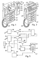
- a first embodiment of the pay phone apparatus of a pay phone system is shown.
- the apparatus is an auxiliary apparatus designated 10 and connected to a conventional coin operated pay phone apparatus 12.
- the apparatus 12 comprises a housing 14, in which a coin container (not shown in the drawing) is enclosed.
- a coin receiving slot 16 is provided together with a return pushbutton 18 and a dial means 20.
- a receiver 24 is received on a hook of the apparatus including switching means for turning the apparatus into operation.
- the receiver 24 is connected to the housing 14 through a coiled cord 26.
- a plate informs an operator how to use the telephone apparatus.
- the auxiliary apparatus 10 comprises a housing 28 and is operated by means of a magnetic card which is received in a magnetic card receiving slit 30 on the front surface of the apparatus housing 24.
- the auxiliary apparatus 10 further comprises a display 32 arranged at the upper end of the front surface of the housing 28 and further two manually operable buttons 33 and 34 serving the purpose of switching the pay phone apparatus assembly comprising the auxiliary apparatus 10 and the coin operated pay phone apparatus 12 into an operational mode in which the telephone call is paid for by the telephone subscriber to whom the telephone call is addressed. This mode of receiving telephone subscriber paying the telephone call is to be described in greater detail below with reference to Fig. 4.
- a presently preferred embodiment of a pay phone apparatus of a pay phone system is shown.
- the pay telephone apparatus is designated 40 in its entirety and comprises the above housing 14 and the receiver 24 received in the recess 22 of the housing 14 and further connected through the cord 26 to the housing 14.
- the dial means 20 and the return pushbutton 18 the embodiment shown in Fig. 2 comprises a card receiving slit 42 basically identical to the slit 30 shown in Fig. 1, a keyboard dial means 44, a display 46 basically corresponding to the display 32 shown in Fig. 1 and two pushbuttons 48 and 49 basically corresponding to the pushbuttons 33 and 34 shown in Fig. 1.
- the operation of the apparatus 40 will be evident from the detailed description below with reference to Fig. 4.
- a schematical view of a pay phone system is shown.
- the system comprises a number of pay phone apparatuses 40, e.g. of the type shown in Fig. 2, which are connected through telephone lines to a local computer 50, e.g. at the telephone central 52, and which are further connected to a remote central computer 54, to which one of the pay phone apparatuses 40 is connected directly.
- the pay phone apparatuses 40 are operated by means of magnetic cards 55, 56, and 57, preferably of the kind described in Applicants' co-pending PCT-application PCT/DK84/00118 and basically conform to ISO Standard 2894.
- the pay telephone apparatuses 40 may be operated by means of a magnetic card issued by a credit card organisation.
- a computer system of a first credit card organisation is shown at 58 and a second computer system of a second credit card organisation is shown at 60.
- the remote central computer 54 further communicates through a telephone line with a terminal 59, e.g. a terminal at a telephone shop.
- a telephone apparatus 40 (at the lower right-hand side of Fig. 3) which communicates with the remote central computer 54 directly, includes a storage means as will be described in greater detail below with reference to Figs. 4 and 5, and which is addressed from the remote central computer 54 and includes data identifying legal magnetic cards and illegal magnetic cards.
- a magnetic card e.g. the card 55 shown in Fig. 3
- the data stored in the magnetic strip on the card is read from the card and input to a storage means of the pay phone apparatus.
- the data read from the magnetic card and the data transferred from the remote central computer 54 to the above storage means of the pay phone apparatus are compared, and on the basis of the comparison, the card is identified as a legal card, or alternatively, as an illegal card, and it is further checked if the amount represented by data read from the card and representing a maximum telephone call duration is different from zero and has not been altered to a value exceeding the value written in the magnetic card at the conclusion of the preceding telephone call paid for by means of the card in question.
- the card is identified as a legal card and further a card allowing for a telephone call in that the amount is different from zero and has not been altered to a higher value
- the pay phone apparatus is enabled for a telephone call, and the operator is through the display means 46 of the apparatus, vide Fig. 2, invited to input a telephone number by means of the keyboard dial means 44.
- the total amount read from the card 55 is not reduced to zero during the telephone call, the reduced amount is written in the card at the conclusion of the telephone call prior to the returning of the card to the operator from the magnetic card receivng slit 42.
- the reduced amount of the card is stored in the apparatus and at a later time transferred to the remote central computer 54, in which the data are processed, the data are cross-checked relative to data input from other pay phone apparatuses and from local computers such as the local computer 50, and on the basis of the data processing in the remote central computer 54, any illegal cards i.e. cards which have been altered or otherwise tampered with are identified, and data identifying these cards are output from the remote central computer 54 to the storage means of the individual pay phone apparatus 40.
- the pay phone apparatuses at the left hand-side of Fig. 3 are connected to a local computer 50, which includes the storage means which is addressed from the remote central computer 54 and includes data identifying legal and illegal cards, and further the storage means into which the data read from the cards 55-57 are stored, together with the comparison block in which the data read from the card and the data previously supplied from the remote central computer 54 are compared to one another in order to identify the card in question as a legal or as an illegal card.
- the pay phone apparatus 40 In case a card issued by a credit card organisation, e.g. the credit card organisation running the computer system 58, is input to the pay phone apparatus 40, the data read from the card identifies the card as a credit card, and the pay phone apparatus addresses the remote central computer 54, which further addresses the credit card computer system in which the authenticity of the card is verified. Provided the authenticity of the card issued by the credit card organization is verified, the pay phone apparatus 40 is enabled for a telephone call, i.e. the operator is invited to input a telephone number by means of the keyboard dial means 44 as discussed above.
- a telephone call i.e. the operator is invited to input a telephone number by means of the keyboard dial means 44 as discussed above.
- the data read from the card issued by the credit card organization is stored in the pay phone apparatus together with the amount representing the telephone call duration and at a later time when the data stored in the pay phone apparatus are transferred to the remote central computer 54, and further transferred therefrom to the computer system 50 so as to debit the telephone call to the credit card account corresponding to the credit card employed for the telephone call.
- the remote central computer 54 may be adapted to automatically limit the duration of the telephone call to a predetermined value.
- the terminal 59 renders it possible to check the history of a particular card by addressing the remote central computer 54 in order to check a complaint regarding a magnetic card.
- a block diagram of the pay phone apparatus 40 is shown.
- the apparatus comprises centrally a microprocessor 62, which controls the overall operation of the apparatus and is connected to the individual block of the apparatus to be described below.
- the microprocessor 62 is connected to the keyboard dial means 44, the display 46 and an audio-circuit block 64, to which the receiver 24 is connected.
- the microprocessor 62 is further connected to a magnetic reading and writing block 66 including the magnetic card receiving slit 42, a magnetic reading head 67, a magnetic writing head 68 and magnetic card advancing pulleys 69 and 70 which may be idler or drive pulleys or combined idler and drive pulleys.
- the microprocessor 62 is also connected to a voice generator block 72, which is further connected to a block 74 including the pushbuttons 48 and 49, which activate switches of the block 74. Furthermore, the microprocessor 62 is connected to a first store 76, into which data read from a card by means of the magnetic reading head 67 are input through the microprocessor 62, and further to a second store 78, into which data identifying legal and illegal parts are input from the remote central computer 54 shown in Fig. 3 through an input/output interface block 82 connected to a telephone line and further through an encryption/decryption block 80. Alternatively, a decryption block may be included in the microprocessor 62 so that data transferred from the remote central computer 54 shown in Fig.
- the data read from the magnetic card or cards, e.g. the cards 55, 56 and 57 shown in Fig. 3 are further in an encrypted state and are stored in the first store 76 in an encrypted state. Consequently, a criminal who attempts to disclose the inherent information stored in the stores 76 and 78 by tampering with the pay phone apparatus 40 is not able to obtain any relevant information regarding the pay phone system as the data stored in the stores 76 and 78 are in an encrypted state.
- the data transferred to and from the individual blocks of the apparatus i.e. to and from the reading and writing block 66 and to and from the stores 76 and 78 and further transferred to the apparatus or from the apparatus through the telephone line are in an encrypted state.
- the data are disclosed in a plain text exclusively.
- data read from cards received in the magnetic card receiving slit 42 are input to the first store 76 and stored therein and further compared to data stored in the second store 78 and representing legal and illegal cards. On the basis of the comparison, it is determined whether the card is a legal card or not. Provided the card is identified as a legal card and the amount allowing for a telephone call and read from the card is an amount larger than zero, the pay phone apparatus is enabled for a telephone call. The operator is informed by means of the display 46 to input a telephone number by means of a keyboard dial means 44. The telephone number dialled is displayed on the display 46 and as the connection is established, the display 46 is switched into displaying the amount allowing for the telephone call.
- the amount is gradually reduced, and the reduced amount is displayed to the operator on the display 46.
- the reduced amount is written into the magnetic card by means of the writing head 68 of the block 66.
- the pay phone apparatus automatically interrupts the telephone call, and the recuced amount, i.e. the amount zero is written into the magnetic card, which is consequently converted into a valueless card.
- the operator activates one of the pushbuttons 48 and 49, which further activates the voice generator block 72 and the microprocessor 62 and converts the apparatus into an operational mode, in which the telephone call is to be debited to the telephone subscriber receiving the telephone call.
- the pushbutton in question i.e. one of the pushbuttons 48 and 49
- the operator is invited to dial the telephone number by means of the keyboard dial means 44 the telephone number being stored in the first store 76, and as the connection has been established, the voice generator block 72 outputs an audio signal to the telephone line asking the telephone subscriber receiving the telephone call, if he will accept to pay for the telephone call.
- the telephone subscriber If the telephone subscriber is willing to accept to pay for the telephone call, he activates the dial means of his telephone apparatus in a prescribed manner, i.e. he dials a number asked for by the signal generated by the voice generator block 72 by means of the dial means of his telephone apparatus in order to generate a sequence of a tone burst signals which are supplied through the telephone line to the pay phone apparatus.
- the amount representing the telephone call duration is also stored in the first store 76 and at a later time, when the data of the store 76 are transferred to the remote central computer 54, debited the account of the telephone subscriber.
- Fig. 5 the verification routine carried out in the pay phone apparatus 40 or alternatively in the auxiliary apparatus 10 connected to the conventional coin operated pay phone apparatus is illustrated in a route diagram.
- Data read from the card 55 identifying the card, e.g. by its number or the like, are compared to data output from the store 78 in a verification block 84.
- Data read from the card 55 and representing an amount allowing for a telephone call are compared to data output from the store 76 in a further verification block 86.
- a further logical decision block 88 enables the pay phone apparatus for a telephone call.
- the keyboard dial means 44 further activates a debiting pulse generator block 90, which supplies debiting pulses to an arithmetric block 92, which further receives the amount read from the card 55 and reduces the amount in response to the debiting pulses supplied from the debiting pulse generator block 90.
- the actual or reduced amount is displayed on the display 46 and input to the store 76 and further supplied to the block 94, which is adapted to interrupt the telephone conversation as the amount is reduced below a predetermined threshold, such as a zero threshold.
- the store 76 outputs the reduced amount to the magnetic writing head 68 shown in Fig. 4 by means of which the amount is written in the card 55.
- the data stored in the store 76 are output to the remote central computer at an appropriate time, e.g. by night, and in the remote central computer, the data are processed as described above, and the data stored in the store 78 and identifying legal and illegal cards are updated in response to the processing of the data in the remote central computer.
- the store 76, the store 78, the verification block 84, the verification block 86, the logical decision block 88 and the microprocessor 62 controlling the overall operation of the apparatus are housed in the local computer 50.
- a number of pay phone apparatuses of the type shown in the lower right-hand side of Fig. 3 may commonly comprise the above identified controlling, storing and dicision blocks, e.g. in applications in which a number of pay phone apparatuses are arranged in adjacent telephone booths, e.g. at railway stations, airports, etc.
- the receiving subscriber paying principle may be adapted to other telephone apparatuses such as conventional telephone subscriber apparatuses and is a universially applicable debiting principle.
Landscapes
- Engineering & Computer Science (AREA)
- Business, Economics & Management (AREA)
- General Physics & Mathematics (AREA)
- Physics & Mathematics (AREA)
- Accounting & Taxation (AREA)
- Computer Security & Cryptography (AREA)
- Theoretical Computer Science (AREA)
- General Business, Economics & Management (AREA)
- Computer Networks & Wireless Communication (AREA)
- Strategic Management (AREA)
- Signal Processing (AREA)
- Finance (AREA)
- Microelectronics & Electronic Packaging (AREA)
- Telephonic Communication Services (AREA)
- Financial Or Insurance-Related Operations Such As Payment And Settlement (AREA)
- Telephone Function (AREA)
- Coin-Freed Apparatuses For Hiring Articles (AREA)
- Control Of Vending Devices And Auxiliary Devices For Vending Devices (AREA)
- Electrochromic Elements, Electrophoresis, Or Variable Reflection Or Absorption Elements (AREA)
- Inert Electrodes (AREA)
- Meter Arrangements (AREA)
Claims (31)
- Un système de service à paiement, comprenant au moins un appareil de service à paiement et un ordinateur central à distance, l'appareil de service à paiement communiquant avec l'ordinateur central par l'intermédiaire d'une ligne de transmission, l'appareil de service à paiement étant mis en oeuvre au moyen d'un jeton comprenant des données, lisibles sur le jeton et identifiant le jeton, et représentant en outre une valeur correspondant à l'exécution d'un service qui peut être autorisée; l'appareil de service à paiement comprenant:
un moyen pour recevoir le jeton,
un moyen de lecture pour lire lesdites données lisibles sur le jeton reçu dans le moyen récepteur de jeton,
un moyen d'écriture pour écrire les données sur le jeton,
un premier moyen de mémorisation relié au moyen de lecture pour mémoriser des données lues sur le jeton par les moyens de lecture, et pouvant en outre être relié à la ligne de transmission pour transférer des données d l'ordinateur central à distance par l'intermédiaire de la ligne de transmission,
un deuxième moyen de mémorisation qui peut être adressé, par l'intermédiaire de la ligne de transmission, à partir de l'ordinateur central à distance et qui est destiné à mémoriser des données transférées depuis ce dernier,
un moyen comparateur relié au premier moyen de mémorisation et au deuxième moyen de mémorisation pour comparer les données mémorisées dans le premier moyen de mémorisation avec les données mémorisées dans le deuxième moyen de mémorisation de façon à identifier le jeton en tant que jeton légal, ou, en variante, en tant que jeton illégal et pour engendrer en outre un signal d'acceptation pour valider l'appareil de service à paiement en vue de l'exécution d'un service, pourvu que le jeton soit identifié en tant que jeton légal ou, en variante, pour engendrer et envoyer un signal de rejet au moyen récepteur, pourvu que le jeton soit identifié en tant que jeton illégal, afin d'amener le moyen récepteur à rejeter le jeton, ledit signal d'acceptation ou, en variante, ledit signal de rejet étant mémorisé dans le premier moyen de mémorisation,
un moyen de débit pour engendrer un signal représentant une valeur à débiter correspondant à la durée de l'exécution d'un service,
un moyen de soustraction relié au premier moyen de mémorisation et au moyen de débit et destiné à soustraire, de ladite valeur représentée par les données lues sur le jeton, le signal de débit de façon à réduire la valeur, la valeur réduite étant mémorisée dans le premier moyen de mémorisation et étant en outre envoyée au moyen d'écriture et écrit dans ledit jeton par le moyen d'écriture à la conclusion de l'exécution du service, et
un moyen de porte relié au moyen de soustraction et recevant ladite valeur réduite pendant l'exécution du service et destiné à comparer la valeur réduite et un seuil prédéterminé afin d'interrompre l'exécution du service lorsque la valeur réduite tombe au-dessous dudit seuil prédéterminé;
l'appareil de service à paiement étant apte à envoyer à la ligne de transmission des données mémorisées dans le premier moyen de mémorisation pour transférer les données à l'ordinateur central à distance en vue d'une mémorisation ou d'un traitement dans celui-ci après la conclusion de l'exécution du service; et
l'ordinateur central à distance étant apte à transférer des données identifiant des jetons légaux et des données identifiant des jetons illégaux au deuxième moyen de mémorisation de l'appareil de service à paiement par l'intermédiaire de la ligne de transmission lorsque l'appareil de service à paiement n'est pas en fonctionnement. - Un système de service à paiement selon la revendication 1, l'appareil de service à paiement étant un appareil téléphonique à paiement, la ligne de transmission étant une ligne téléphonique, et l'exécution du service étant un appel téléphonique, l'appareil téléphonique à paiement communiquant avec un standard téléphonique par l'intermédiaire de la ligne téléphonique.
- Un système de service à paiement selon la revendication 2, plusieurs appareils téléphoniques à paiement comprenant en commun le premier moyen de mémorisation, le deuxième moyen de mémorisation et le moyen comparateur.
- Un système de service à paiement selon la revendication 1, l'appareil de service à paiement étant un appareil téléphonique à paiement, le système comprenant en outre un ordinateur local, l'appareil téléphonique à paiement communiquant avec un standard téléphonique et avec l'ordinateur local par l'intermédiaire d'une ligne téléphonique et, en outre, avec l'ordinateur central à l'aide d'une ligne de transmission de données ou d'une autre ligne téléphonique, l'exécution du service étant un appel téléphonique;
le moyen de lecture pouvant être relié à la ligne téléphonique pour transférer des données à l'ordinateur local par l'intermédiaire de la ligne téléphonique,
le moyen d'écriture pouvant être relié à la ligne téléphonique pour recevoir des données depuis l'ordinateur local par l'intermédiaire de la ligne téléphonique,
le premier moyen de mémorisation, le deuxième moyen de mémorisation et le moyen comparateur étant inclus dans l'ordinateur local,
l'ordinateur local étant apte à envoyer, vers la ligne de transmission de données ou l'autre ligne téléphonique des données mémorisées dans le premier moyen de mémorisation pour transférer des données vers l'ordinateur central à distance en vue d'une mémorisation ou d'un traitement dans ce dernier. - Un système de service à paiement selon la revendication 4, l'ordinateur local étant affecté à plusieurs appareils téléphoniques à paiement.
- Un système de service à paiement selon l'une quelconque des revendications 2 à 5, l'appareil téléphonique à paiement étant en outre apte à être mis en oeuvre au moyen d'un jeton différent, représentant un jeton de crédit et recevable dans le moyen récepteur de l'appareil téléphonique à paiement et comprenant en outre des données qui peuvent être lues dans le jeton et identifiant le jeton, l'ordinateur central à distance étant relié ou pouvant être relié à un ordinateur additionnel d'une organisation de crédit;
le moyen comparateur étant en outre apte à identifier le jeton en tant que jeton de crédit sur la base de la comparaison des données mémorisées dans le premier moyen de mémorisation avec les données mémorisées dans le deuxième moyen de mémorisation et à adresser le premier moyen de mémorisation de façon à amener le premier moyen de mémorisation à envoyer à la ligne téléphonique les données qui y sont mémorisées en vue d'un transfert des données vers l'ordinateur central à distance, pourvu que le jeton ait été identifié en tant que jeton de crédit;
l'ordinateur central à distance étant en outre apte à adresser l'ordinateur additionnel de l'organisation de crédit lorsqu'il reçoit des données provenant de l'appareil téléphonique à paiement concernant le jeton de crédit et pour transférer les données à l'ordinateur additionnel afin d'amener l'ordinateur additionnel à vérifier l'authenticité du jeton de crédit et, pourvu que le jeton de crédit ait été vérifié en tant que jeton de crédit légal par l'ordinateur additionnel, à valider l'appareil téléphonique à paiement en vu d'un appel téléphonique;
et l'appareil téléphonique à paiement étant en outre apte à envoyer à la ligne téléphonique, en vu d'un transfert par l'intermédiaire de celle-ci à l'ordinateur central en cas de validation à distance, le signal de débit engendré par le moyen de débit pendant l'appel téléphonique;
et l'ordinateur central à distance étant en outre apte à transférer à l'ordinateur additionnel le signal de débit reçu depuis l'appareil téléphonique à paiement. - Un système de service à paiement selon l'une quelconque des revendications 2 à 6, l'appareil téléphonique à paiement comprenant en outre un moyen de cadran incluant des moyens commutateurs à mettre en oeuvre manuellement pour engendrer une séquence de signaux de paquets de tonalités et pour envoyer la séquence au standard téléphonique par l'intermédiaire de la ligne téléphonique pour adresser des moyens sélecteurs du standard téléphonique.
- Un système de service à paiement selon la revendication 7, l'appareil téléphonique à paiement comprenant en outre un autre moyen de commutateur à manoeuvrer à la main et un moyen générateur de voix, l'autre moyen commutateur à manoeuvre manuellement étant relié au moyen générateur de voie et apte à activer ce dernier, le premier moyen de mémorisation étant en outre apte à mémoriser la séquence de signaux de paquets de tonalités, engendrée à l'aide du moyen de commutateur à manoeuvrer à la main du moyen du cadran, le moyen générateur de voie étant apte à engendrer un signal de demande et pouvant être relié à la ligne téléphonique de façon à engendrer et à envoyer à la ligne téléphonique le signal de demande lorsqu'il est activé par l'autre moyen de commutateur à manoeuvrer manuellement, le signal de demande étant en outre envoyé à l'abonné téléphonique auquel est adressé la séquence de signaux de paquets de tonalités engendrée au moyen du moyen commutateur à manoeuvrer à la main du moyen de cadran, et l'appareil téléphonique à paiement étant en outre apte à être validé pour l'appel téléphonique par un signal d'acceptation fourni à l'appareil téléphonique à paiement à partir de l'appareil de l'abonné téléphonique en réponse au signal de demande.
- Un système de service à paiement selon l'une quelconque des revendications 2 à 8, l'appareil téléphonique à paiement comprenant en outre un moyen récepteur incluant au moins deux transducteurs électro-acoustiques dont l'un est apte à convertir l'énergie acoustique en énergie électrique et envoyer ladite énergie acoustique à la ligne téléphonique lorsque l'appareil téléphonique à paiement est en fonctionnement, et dont un autre est adapté à recevoir l'énergie électrique provenant de la ligne téléphonique et à convertir l'énergie électrique en énergie acoustique, lorsque l'appareil téléphonique à paiement est en fonctionnement.
- Un système de service à paiement selon l'une quelconque des revendications 2 à 9, le premier moyen de mémorisation et le deuxième moyen de mémorisation de l'appareil téléphonique à paiement étant constitués par un premier et un deuxième éléments, respectivement, d'un moyen de mémorisation unique.
- Un système de service à paiement selon l'une quelconque des revendications 2 à 10, le premier moyen de mémorisation de l'appareil téléphonique à paiement étant constitué par une mémoire volatile, et un deuxième moyen de mémorisation de l'appareil téléphonique à paiement étant constitué par la mémoire non volatile.
- Un système de service à paiement selon l'une quelconque des revendications 2 à 11, l'appareil téléphonique à paiement comprenant en outre un moyen central de commande commandant le fonctionnement d'ensemble de l'appareil.
- Un système de service à paiement selon la revendication 12, le moyen central de commande de l'appareil téléphonique à paiement étant constitué par un moyen de micro-ordinateur.
- Un système de service à paiement selon l'une quelconque des revendications 2 à 13 le système téléphonique à paiement comprenant en outre des moyens de chiffrement et de déchiffrement, un moyen de chiffrement étant interconnecté entre le premier moyen de mémorisation et la ligne téléphonique et un moyen de déchiffrement étant interconnecté entre la ligne téléphonique et le deuxième moyen de mémorisation, pour fournir à la ligne téléphonique sous une forme chiffrée des données envoyées par le premier moyen de mémorisation, et pour déchiffrer, depuis un état chiffré vers un état déchiffré, les données transférées depuis l'ordinateur central à distance vers le deuxième moyen de mémorisation respectivement.
- Un système de service à paiement selon l'une quelconque des revendications 2 à 14, l'appareil téléphonique à paiement comprenant en outre un moyen d'affichage relié au moyen comparateur, au moyen soustracteur et au moyen de porte pour afficher l'information correspondant au signal d'acceptation ou, ³en variante, au signal de rejet, fourni par le moyen comparateur afin d'afficher ladite valeur fournie par le moyen soustracteur et pour afficher en outre une information fournie par le moyen de porte.
- Un système de service à paiement selon l'une quelconque des revendications 2 à 15, le jeton étant une carte portant une bande de matière magnétique agencée sur une surface de côté de la carte, les moyens de lecture et d'écriture de l'appareil téléphonique à paiement étant des moyens de lecture et d'écriture magnétiques, respectivement.
- Un appareil téléphonique à paiement dans un système de service à paiement selon la revendication 2 et comprenant:
le moyen de recevoir le jeton,
le moyen de lecture,
le moyen d'écriture,
le premier moyen de mémorisation,
le deuxième moyen de mémorisation,
le moyen de débit,
le moyen de soustraction, et
le moyen de porte de l'appareil téléphonique à paiement du système de service à paiement selon la revendication 2. - Un appareil téléphonique à paiement dans un système de service à paiement selon la revendication 4 et comprenant:
le moyen récepteur du jeton,
le moyen de lecture,
le moyen d'écriture,
le moyen de débit,
le moyen de soustraction, et
le moyen de porte de l'appareil téléphonique à paiement du système de service à paiement selon la revendication 4. - Un appareil téléphonique à paiement selon l'une quelconque des revendications 17 ou 18, l'appareil téléphonique à paiement étant en outre apte à être mis en oeuvre au moyen d'un jeton différent, représentant un jeton de crédit et recevable dans le moyen récepteur de l'appareil téléphonique à paiement et comprenant en outre des données qui peuvent être lues dans le jeton et identifiant le jeton, l'ordinateur central à distance étant relié ou pouvant être relié à un ordinateur additionnel d'une organisation de crédit;
le moyen comparateur étant en autre apte à identifier le jeton en tant que jeton de crédit sur la base de la comparaison des données mémorisées dans le premier moyen de mémorisation avec les données mémorisées dans le deuxième moyen de mémorisation et à adresser le premier moyen de mémorisation de façon à amener le premier moyen de mémorisation à envoyer à la ligne téléphonique les données qui y sont mémorisées en vue d'un transfert des données vers l'ordinateur central à distance, pourvu que le jeton ait été identifié en tant que jeton de crédit;. - Un appareil téléphonique à paiement selon ` l'une quelconque des revendications 17 à 19, l'appareil téléphonique à paiement comprenant en outre un moyen de cadran incluant des moyens commutateurs à mettre en oeuvre manuellement pour engendrer une séquence de signaux de paquets de tonalités et pour envoyer la séquence au standard téléphonique par l'intermédiaire de la ligne téléphonique pour adresser des moyens sélecteurs du standard téléphonique.
- Un appareil téléphonique à paiement selon la revendication 20, l'appareil téléphonique à paiement comprenant en outre un autre moyen de commutateur à manoeuvrer à la main et un moyen générateur de voix, l'autre moyen commutateur à manoeuvre manuellement étant relié au moyen générateur de voie et apte à activer ce dernier, le premier moyen de mémorisation étant en outre apte à mémoriser la séquence de signaux de paquets de tonalités, engendrée à l'aide du moyen de commutateur à manoeuvrer à la main du moyen du cadran, le moyen générateur de voie étant apte à engendrer un signal de demande et pouvant être relié à la ligne téléphonique de façon à engendrer et à envoyer à la ligne téléphonique le signal de demande lorsqu'il est activé par l'autre moyen de commutateur à manoeuvrer manuellement, le signal de demande étant en outre envoyé à l'abonné téléphonique auquel est adressé la séquence de signaux de paquets de tonalités engendrée au moyen du moyen commutateur à manoeuvrer à la main du moyen de cadran, et l'appareil téléphonique à paiement étant en outre apte à être validé pour l'appel téléphonique par un signal d'acceptation fourni à l'appareil téléphonique à paiement à partir de l'appareil de l'abonné téléphonique en réponse au signal de demande.
- Un appareil téléphonique à paiement selon l'une quelconque des revendications 17 à 21, l'appareil téléphonique à paiement comprenant en outre un moyen récepteur incluant au moins deux transducteurs électro-acoustiques dont l'un est apte à convertir l'énergie acoustique en énergie électrique et envoyer ladite énergie acoustique à la ligne téléphonique lorsque l'appareil téléphonique à paiement est en fonctionnement, et dont un autre est adapté à recevoir l'énergie électrique provenant de la ligne téléphonique et à convertir l'énergie électrique en énergie acoustique, lorsque l'appareil téléphonique à paiement est en fonctionnement.
- Un appareil téléphonique à paiement selon l'une quelconque des revendications 17 ou 19 à 22, le premier moyen de mémorisation et le deuxième moyen de mémorisation de l'appareil téléphonique à paiement étant constitués par un premier et un deuxième éléments respectivement d'un moyen de mémorisation unique.
- Un appareil téléphonique à paiement selon l'une quelconque des revendications 17 ou 19 à 23, le premier moyen de mémorisation de l'appareil téléphonique à paiement étant constitué par une mémoire volatile, et un deuxième moyen de mémorisation de l'appareil téléphonique à paiement étant constitué par la mémoire non volatile.
- Un appareil téléphonique à paiement selon l'une quelconque des revendication 16 à 20, l'appareil téléphonique à paiement comprenant en outre un moyen central de commande commandant le fonctionnement d'ensemble de l'appareil.
- Un appareil téléphonique à paiement selon la revendication 25, le moyen central de commande de l'appareil téléphonique à paiement étant constitué par un moyen de micro-ordinateur.
- Un appareil téléphonique à paiement selon l'une quelconque des revendications 17 ou 19 à 25, le système téléphonique à paiement comprenant en outre des moyens de chiffrement et de déchiffrement, un moyen de chiffrement étant interconnecté entre le premier moyen de mémorisation et la ligne téléphonique et un moyen de déchiffrement étant interconnecté entre la ligne téléphonique et le deuxième moyen de mémorisation, pour fournir à la ligne téléphonique sous une forme chiffrée des données envoyées par le premier moyen de mémorisation, et pour déchiffrer, depuis un état chiffré vers un état déchiffré, les données transférées depuis l'ordinateur central à distance vers le deuxième moyen de mémorisation respectivement.
- Un appareil téléphonique à paiement selon l'une quelconque des revendications 17 à 27, l'appareil téléphonique à paiement comprenant en outre un moyen d'affichage relié au moyen comparateur, au moyen soustracteur et au moyen de porte pour afficher l'information correspondant au signal d'acceptation ou, ²en variante, au signal de rejet, fourni par le moyen comparateur afin d'afficher ladite valeur fournie par le moyen soustracteur et pour afficher en outre une information fournie par le moyen de porte.
- Un appareil téléphonique à paiement selon l'une quelconque des revendications 17 à 28, le jeton étant une carte portant une bande de matière magnétique agencée sur une surface de côté de la carte, les moyens de lecture et d'écriture de l'appareil téléphonique à paiement étant des moyens de lecture et d'écriture magnétiques, respectivement.
- Un ordinateur local dans un système de service à paiement selon la revendication 4 et comprenant:
le premier moyen de mémorisation,
le deuxième moyen de mémorisation,
le moyen comparateur de l'ordinateur local du système de service à paiement selon la revendication 4. - Un ordinateur local selon la revendication 30, l'ordinateur local étant affecté à plusieurs appareils téléphoniques à paiement.
Priority Applications (1)
| Application Number | Priority Date | Filing Date | Title |
|---|---|---|---|
| AT85116107T ATE64051T1 (de) | 1984-12-18 | 1985-12-17 | Fernsprechbezahlsystem oder servicebezahlsystem. |
Applications Claiming Priority (2)
| Application Number | Priority Date | Filing Date | Title |
|---|---|---|---|
| DK6086/84 | 1984-12-18 | ||
| DK608684A DK608684D0 (da) | 1984-12-18 | 1984-12-18 | Betalingstelefon |
Publications (2)
| Publication Number | Publication Date |
|---|---|
| EP0185365A1 EP0185365A1 (fr) | 1986-06-25 |
| EP0185365B1 true EP0185365B1 (fr) | 1991-05-29 |
Family
ID=8147299
Family Applications (1)
| Application Number | Title | Priority Date | Filing Date |
|---|---|---|---|
| EP85116107A Expired - Lifetime EP0185365B1 (fr) | 1984-12-18 | 1985-12-17 | Système téléphonique à paiement ou système de service à paiement |
Country Status (6)
| Country | Link |
|---|---|
| EP (1) | EP0185365B1 (fr) |
| AT (1) | ATE64051T1 (fr) |
| DE (1) | DE3583007D1 (fr) |
| DK (1) | DK608684D0 (fr) |
| NO (1) | NO171879C (fr) |
| WO (1) | WO1986003915A1 (fr) |
Cited By (4)
| Publication number | Priority date | Publication date | Assignee | Title |
|---|---|---|---|---|
| RU2115256C1 (ru) * | 1990-04-19 | 1998-07-10 | Телефоника де Эспанья С.А. | Система управления модульными телефонами-автоматами |
| DE19814165A1 (de) * | 1998-03-30 | 1999-10-07 | Siemens Ag | Kommunikationsendgerät zur Aufnahme und Auswertung von Wertkarten oder Münzen |
| US6704563B1 (en) | 1998-08-11 | 2004-03-09 | Boston Communications Group, Inc. | Systems and methods for prerating costs for a communication event |
| US7187928B1 (en) | 1998-11-24 | 2007-03-06 | Boston Communications Group, Inc. | Call delivery systems for roaming prepaid subscribers |
Families Citing this family (63)
| Publication number | Priority date | Publication date | Assignee | Title |
|---|---|---|---|---|
| GB2179524B (en) * | 1985-08-12 | 1989-08-02 | Oki Electric Ind Co Ltd | Radio telephone equipment |
| GB8522427D0 (en) * | 1985-09-10 | 1985-10-16 | Plessey Co Plc | Credit transaction arrangments |
| EP0257596B1 (fr) * | 1986-08-26 | 1992-11-11 | Siemens Aktiengesellschaft | Procédé pour reconnaître un usage illicite d'une carte à circuit intégré |
| CA1276239C (fr) * | 1986-10-01 | 1990-11-13 | Arlene J. Harris | Systeme radio mobile cellulaire pour cartes de credit |
| FI77550C (fi) * | 1987-07-29 | 1989-03-10 | Nokia Mobira Oy | Foerfarande foer sammankoppling till anvaendarens kort vid en mobilradiotelefon. |
| GB2211050A (en) * | 1987-10-15 | 1989-06-21 | Gen Electric Co Plc | Telephone system |
| GB2211376B (en) * | 1987-10-19 | 1991-07-10 | Mars Inc | Telephone set |
| JPH0648838B2 (ja) * | 1988-07-18 | 1994-06-22 | 株式会社田村電機製作所 | 公衆電話機 |
| GB2225915A (en) * | 1988-10-13 | 1990-06-13 | In Business Enhancement Limite | Phone card only allows use of stored numbers thereon |
| US4920562A (en) * | 1989-01-23 | 1990-04-24 | Intellicall, Inc. | Automatic generation of billing records at a telephone paystation |
| US4933966A (en) * | 1989-01-23 | 1990-06-12 | Intellicall, Inc. | Method and apparatus for performing an automated collect call |
| US4908852A (en) * | 1989-01-23 | 1990-03-13 | Intellicall, Inc. | Method and apparatus for altering the access format of telephone calls |
| US5960072A (en) * | 1989-01-23 | 1999-09-28 | Intellicall, Inc. | Method and apparatus for altering the access format of telephone calls |
| US4975942A (en) * | 1989-07-21 | 1990-12-04 | The Boston Communications Group | Credit/calling card pay telephone method and system employing telephone unit local card-checking and other intelligence cooperative with local personal host computer |
| CA2020240C (fr) * | 1989-07-31 | 1994-05-24 | Gary Lewis Dorst | Dispositif assistance semi-automatique pour les telecommunications |
| JP2686502B2 (ja) * | 1989-11-20 | 1997-12-08 | 株式会社田村電機製作所 | プリペイドカード管理システム |
| DE68917606T2 (de) * | 1989-12-01 | 1995-01-26 | Bell Telephone Mfg | Fernsprechbezahlsystem. |
| FI88842C (fi) * | 1990-03-22 | 1993-07-12 | Nokia Mobile Phones Ltd | Kontroll av kortsanslutning |
| AT399599B (de) * | 1990-10-04 | 1995-06-26 | Uher Ag | Vorrichtung zur elektrizitätszählung |
| JPH04156757A (ja) * | 1990-10-19 | 1992-05-29 | Nec Corp | 加入電話システムにおける課金方式 |
| US5177342A (en) † | 1990-11-09 | 1993-01-05 | Visa International Service Association | Transaction approval system |
| CA2076433C (fr) * | 1991-10-31 | 1998-08-18 | Brenda B. Amarant | Surveillance des frais debites a un compte a limite fixee |
| KR950003793B1 (ko) * | 1992-06-19 | 1995-04-18 | 한국전기통신공사 | 주화처리장치 |
| KR940001633A (ko) * | 1992-06-19 | 1994-01-11 | 이해욱 | 주화 및 카드 겸용 공중전화기 및 그 제어방법 |
| US5351290A (en) * | 1992-09-11 | 1994-09-27 | Intellicall, Inc. | Telecommunications fraud prevention system and method |
| DE59307854D1 (de) * | 1992-12-01 | 1998-01-29 | Landis & Gyr Business Support | Verfahren zur Abgeltung von Dienstleistungen und/oder Waren und Einrichtung zur Durchführung des Verfahrens |
| US5463679A (en) * | 1993-04-27 | 1995-10-31 | Tamura Electrics Works, Ltd. | Public telephone system |
| JP2852845B2 (ja) * | 1993-04-27 | 1999-02-03 | 株式会社田村電機製作所 | 公衆電話システム |
| NL9301271A (nl) * | 1993-07-20 | 1995-02-16 | Nederland Ptt | Werkwijze en inrichting voor het registreren van gebruiksgegevens van op een betaalkaart werkende toestellen. |
| US5914471A (en) * | 1993-07-20 | 1999-06-22 | Koninklijke Ptt Nederland N.V. | Method and apparatus for recording usage data of card operated devices |
| NZ513722A (en) * | 1994-12-02 | 2001-09-28 | British Telecomm | Communications terminal |
| AU760401B2 (en) * | 1994-12-02 | 2003-05-15 | British Telecommunications Public Limited Company | A communications apparatus and a communications signal |
| AU743450B2 (en) * | 1994-12-02 | 2002-01-24 | British Telecommunications Public Limited Company | A communications terminal |
| US5946614A (en) * | 1996-06-13 | 1999-08-31 | Qualcomm Incorporated | Payphone metering in a wireless telephone system |
| RU2126169C1 (ru) * | 1997-12-03 | 1999-02-10 | Веселов Владимир Федорович | Способ защиты частной информации пользователя коллективной системы обработки информации |
| JP2002503058A (ja) * | 1998-02-05 | 2002-01-29 | ミツビシ インターナショナル ゲゼルフシャフト ミット ベシュレンクテル ハフツング | アドレスディレクトリ生成方法 |
| EP0963097A1 (fr) * | 1998-06-05 | 1999-12-08 | Siemens Aktiengesellschaft | Terminal de communications avec traitement des cartes de paiement ou des pièces de monnaie |
| DE29812711U1 (de) * | 1998-07-16 | 1998-10-01 | Siemens AG, 80333 München | Öffentlich zugängliches Kommunikationsendgerät |
| EP0984611A1 (fr) * | 1998-08-31 | 2000-03-08 | Siemens Aktiengesellschaft | Terminal de communications avec appareil téléphonique à cartes et appareil récepteur de pièces de monnaie |
| US6639981B1 (en) | 1999-04-05 | 2003-10-28 | Tekelec | Methods and systems for routing signaling messages associated with ported subscribers in a communications network |
| FR2793979B1 (fr) * | 1999-05-18 | 2001-06-29 | Schlumberger Systems & Service | Procede de gestion de donnees par un module de securite |
| DE10012392B4 (de) * | 1999-06-21 | 2004-01-29 | T-Mobile Deutschland Gmbh | Verfahren und Einrichtung zum Zugang zu einem Telekommunikationsnetz und zur Abrechnung von Telekommunikationsdienstleistungen |
| EA003306B1 (ru) * | 1999-08-13 | 2003-04-24 | Казовский Наум Иосифович | Способ предоставления транспортных и телекоммуникационных услуг, автоматизированная система для предоставления транспортных и телекоммуникационных услуг и транспортная карта с магнитной полосой, предназначенная для предоставления телекоммуникационных услуг |
| RU2246795C2 (ru) * | 2000-09-26 | 2005-02-20 | Общество с ограниченной ответственностью "Аллайд Глобал" (ООО "Allied Global") | Таксофонный комплекс |
| US7899167B1 (en) | 2003-08-15 | 2011-03-01 | Securus Technologies, Inc. | Centralized call processing |
| US8000269B1 (en) | 2001-07-13 | 2011-08-16 | Securus Technologies, Inc. | Call processing with voice over internet protocol transmission |
| US7505406B1 (en) | 2001-07-13 | 2009-03-17 | Evercom Systems, Inc. | Public telephone control with voice over internet protocol transmission |
| US9026468B2 (en) | 2002-04-29 | 2015-05-05 | Securus Technologies, Inc. | System and method for proactively establishing a third-party payment account for services rendered to a resident of a controlled-environment facility |
| US7916845B2 (en) | 2006-04-13 | 2011-03-29 | Securus Technologies, Inc. | Unauthorized call activity detection and prevention systems and methods for a Voice over Internet Protocol environment |
| US9020114B2 (en) | 2002-04-29 | 2015-04-28 | Securus Technologies, Inc. | Systems and methods for detecting a call anomaly using biometric identification |
| US7860222B1 (en) | 2003-11-24 | 2010-12-28 | Securus Technologies, Inc. | Systems and methods for acquiring, accessing, and analyzing investigative information |
| BR0302530A (pt) * | 2003-07-25 | 2005-04-05 | Siemens Ltda | Sistema centralizado de controle e bloqueio de telefones, gateway e método de controle e bloqueio de telefones |
| US7529357B1 (en) | 2003-08-15 | 2009-05-05 | Evercom Systems, Inc. | Inmate management and call processing systems and methods |
| WO2006009929A2 (fr) | 2004-06-18 | 2006-01-26 | Tekelec | Procedes, systemes et progiciels de selection ou de generation d'article unique de detail d'appel a partir d'une pluralite de ces articles associes a un appel a plusieurs segments |
| US9379898B2 (en) | 2007-05-04 | 2016-06-28 | Tekelec, Inc. | Methods, systems, and computer program products for providing billing and usage data to downstream applications |
| US10796392B1 (en) | 2007-05-22 | 2020-10-06 | Securus Technologies, Llc | Systems and methods for facilitating booking, bonding and release |
| US9584959B2 (en) | 2008-11-24 | 2017-02-28 | Tekelec Global, Inc. | Systems, methods, and computer readable media for location-sensitive called-party number translation in a telecommunications network |
| US9219677B2 (en) | 2009-01-16 | 2015-12-22 | Tekelec Global, Inc. | Methods, systems, and computer readable media for centralized routing and call instance code management for bearer independent call control (BICC) signaling messages |
| US9712341B2 (en) | 2009-01-16 | 2017-07-18 | Tekelec, Inc. | Methods, systems, and computer readable media for providing E.164 number mapping (ENUM) translation at a bearer independent call control (BICC) and/or session intiation protocol (SIP) router |
| US9319318B2 (en) | 2010-03-15 | 2016-04-19 | Tekelec, Inc. | Methods, systems, and computer readable media for performing PCRF-based user information pass through |
| US8903974B2 (en) | 2010-10-05 | 2014-12-02 | Tekelec, Inc. | Methods, systems, and computer readable media for user controlled policy sharing |
| US9332036B2 (en) | 2010-10-15 | 2016-05-03 | Tekelec, Inc. | Methods, systems, and computer readable media for providing user receptivity driven policy in a communications network |
| US8996670B2 (en) | 2011-08-05 | 2015-03-31 | Tekelec, Inc. | Methods, systems, and computer readable media for network metadata based policy control |
Family Cites Families (6)
| Publication number | Priority date | Publication date | Assignee | Title |
|---|---|---|---|---|
| GB1080071A (en) * | 1964-01-26 | 1967-08-23 | Halpern John Wolfgang | Automatic fee charging system |
| IT1023691B (it) * | 1974-09-30 | 1978-05-30 | S I D A S P A | Sistema per effettuare comunica zioni telefoniche in uscita a mezzo di scheda magnetica ed apparecchia tupa per attuare detto sistema |
| CH646026A5 (de) * | 1979-12-03 | 1984-10-31 | Landis & Gyr Ag | Einrichtung zum bargeldlosen telefonieren. |
| IT1128788B (it) * | 1980-06-02 | 1986-06-04 | Sip | Apparecchio telefonico a pregamento con scheda elettronica |
| US4439636A (en) * | 1982-03-09 | 1984-03-27 | Martha Newkirk | Credit card actuated telecommunication access network |
| SE432041B (sv) * | 1982-09-07 | 1984-03-12 | Kurt Katzeff | Anordning vid ett betalkort utnyttjande betalningssystem |
-
1984
- 1984-12-18 DK DK608684A patent/DK608684D0/da not_active Application Discontinuation
-
1985
- 1985-12-17 EP EP85116107A patent/EP0185365B1/fr not_active Expired - Lifetime
- 1985-12-17 AT AT85116107T patent/ATE64051T1/de not_active IP Right Cessation
- 1985-12-17 WO PCT/DK1985/000122 patent/WO1986003915A1/fr not_active Ceased
- 1985-12-17 DE DE8585116107T patent/DE3583007D1/de not_active Expired - Lifetime
-
1986
- 1986-08-14 NO NO863277A patent/NO171879C/no not_active IP Right Cessation
Cited By (5)
| Publication number | Priority date | Publication date | Assignee | Title |
|---|---|---|---|---|
| RU2115256C1 (ru) * | 1990-04-19 | 1998-07-10 | Телефоника де Эспанья С.А. | Система управления модульными телефонами-автоматами |
| DE19814165A1 (de) * | 1998-03-30 | 1999-10-07 | Siemens Ag | Kommunikationsendgerät zur Aufnahme und Auswertung von Wertkarten oder Münzen |
| US6704563B1 (en) | 1998-08-11 | 2004-03-09 | Boston Communications Group, Inc. | Systems and methods for prerating costs for a communication event |
| US7486945B2 (en) | 1998-08-11 | 2009-02-03 | Boston Communications Group, Inc. | Systems and methods for prerating costs for a communication event |
| US7187928B1 (en) | 1998-11-24 | 2007-03-06 | Boston Communications Group, Inc. | Call delivery systems for roaming prepaid subscribers |
Also Published As
| Publication number | Publication date |
|---|---|
| NO863277L (no) | 1986-10-17 |
| WO1986003915A1 (fr) | 1986-07-03 |
| NO171879C (no) | 1993-05-12 |
| ATE64051T1 (de) | 1991-06-15 |
| DK608684D0 (da) | 1984-12-18 |
| NO863277D0 (no) | 1986-08-14 |
| EP0185365A1 (fr) | 1986-06-25 |
| NO171879B (no) | 1993-02-01 |
| DE3583007D1 (de) | 1991-07-04 |
Similar Documents
| Publication | Publication Date | Title |
|---|---|---|
| EP0185365B1 (fr) | Système téléphonique à paiement ou système de service à paiement | |
| US7991694B2 (en) | Mobile electronic commerce system | |
| CN1084007C (zh) | 资金交易装置 | |
| US6332133B1 (en) | Personal electronic settlement system, its terminal, and management apparatus | |
| US4962531A (en) | Transaction system comprising one or more host exchanges and a number of distributed terminal stations | |
| US3938090A (en) | Terminal apparatus | |
| CA1294052C (fr) | Systeme de pari en direct a cartes de saisie programmables | |
| US4882779A (en) | Apparatus for communicating with data systems and a method of communicating with data systems | |
| JP3542603B2 (ja) | Icカードで記憶されたトークンの再評価用システムおよび方法 | |
| EP2287783A1 (fr) | Carte de crédit électronique | |
| KR20000016729A (ko) | 퓨스(puce)카드 시스템에서의보안 프로세스 및 보안 시스템 | |
| AU2331892A (en) | Electronic travel pass | |
| HU213819B (en) | Electronic monetary system, banknote, transfer system, further methods for accepting transacting module, for renewing its voucher, for accepting,removing electronic money, for transfering electronic money among transacting modules, for changing ... | |
| EP0637004B1 (fr) | Méthode pour l'enregistrement de données d'utilisation de dispositifs actionnés par carte | |
| AU763262B2 (en) | Electronic payment method | |
| GB2211050A (en) | Telephone system | |
| EP0818762A2 (fr) | Dispositif codeur, dispositif décodeur et circuit intégré | |
| DK167833B1 (da) | Betalingstelefonanlaeg eller betalingsserviceanlaeg | |
| GB2225915A (en) | Phone card only allows use of stored numbers thereon | |
| US20070226151A1 (en) | Method for Processing a Cashless Payment Transaction | |
| KR0185270B1 (ko) | 텔레뱅킹을 이용한 예매 서비스 장치 및 방법 | |
| EP0341219A2 (fr) | Point d'informations et de téléphone integré et automatique | |
| JP3010152B2 (ja) | 通信不正傍受阻止システム | |
| US7463725B1 (en) | Telephone line use enablement of lottery or fund participation | |
| BG63283B1 (bg) | Метод и система за интерактивен достъп при телематични залози в игри, базиращи се на прогнози |
Legal Events
| Date | Code | Title | Description |
|---|---|---|---|
| PUAI | Public reference made under article 153(3) epc to a published international application that has entered the european phase |
Free format text: ORIGINAL CODE: 0009012 |
|
| AK | Designated contracting states |
Kind code of ref document: A1 Designated state(s): AT BE CH DE FR GB IT LI LU NL SE |
|
| 17P | Request for examination filed |
Effective date: 19861203 |
|
| 17Q | First examination report despatched |
Effective date: 19890216 |
|
| RAP1 | Party data changed (applicant data changed or rights of an application transferred) |
Owner name: GN COMMUNICATIONS A/S |
|
| GRAA | (expected) grant |
Free format text: ORIGINAL CODE: 0009210 |
|
| RAP1 | Party data changed (applicant data changed or rights of an application transferred) |
Owner name: GN COMMUNICATIONS A/S |
|
| AK | Designated contracting states |
Kind code of ref document: B1 Designated state(s): AT BE CH DE FR GB IT LI LU NL SE |
|
| PG25 | Lapsed in a contracting state [announced via postgrant information from national office to epo] |
Ref country code: CH Effective date: 19910529 Ref country code: LI Effective date: 19910529 |
|
| REF | Corresponds to: |
Ref document number: 64051 Country of ref document: AT Date of ref document: 19910615 Kind code of ref document: T |
|
| REF | Corresponds to: |
Ref document number: 3583007 Country of ref document: DE Date of ref document: 19910704 |
|
| ITF | It: translation for a ep patent filed | ||
| REG | Reference to a national code |
Ref country code: CH Ref legal event code: PL |
|
| ET | Fr: translation filed | ||
| NLR4 | Nl: receipt of corrected translation in the netherlands language at the initiative of the proprietor of the patent | ||
| PLBI | Opposition filed |
Free format text: ORIGINAL CODE: 0009260 |
|
| PLBI | Opposition filed |
Free format text: ORIGINAL CODE: 0009260 |
|
| 26 | Opposition filed |
Opponent name: TELENORMA GMBH Effective date: 19920210 |
|
| 26 | Opposition filed |
Opponent name: SIEMENS AKTIENGESELLSCHAFT, BERLIN UND MUENCHEN Effective date: 19920226 Opponent name: TELENORMA GMBH Effective date: 19920210 |
|
| NLR1 | Nl: opposition has been filed with the epo |
Opponent name: TELENORMA GMBH. |
|
| NLR1 | Nl: opposition has been filed with the epo |
Opponent name: SIEMENS AKTIENGESELLSCHAFT |
|
| EPTA | Lu: last paid annual fee | ||
| EAL | Se: european patent in force in sweden |
Ref document number: 85116107.5 |
|
| PLBN | Opposition rejected |
Free format text: ORIGINAL CODE: 0009273 |
|
| STAA | Information on the status of an ep patent application or granted ep patent |
Free format text: STATUS: OPPOSITION REJECTED |
|
| 27O | Opposition rejected |
Effective date: 19950210 |
|
| NLR2 | Nl: decision of opposition | ||
| NLT1 | Nl: modifications of names registered in virtue of documents presented to the patent office pursuant to art. 16 a, paragraph 1 |
Owner name: MONETEL NORDIC A/S |
|
| REG | Reference to a national code |
Ref country code: FR Ref legal event code: CD |
|
| NLT1 | Nl: modifications of names registered in virtue of documents presented to the patent office pursuant to art. 16 a, paragraph 1 |
Owner name: ASCOM NORDIC A/S |
|
| REG | Reference to a national code |
Ref country code: FR Ref legal event code: CD |
|
| BECN | Be: change of holder's name |
Effective date: 19960111 |
|
| REG | Reference to a national code |
Ref country code: FR Ref legal event code: CL |
|
| REG | Reference to a national code |
Ref country code: GB Ref legal event code: 732E |
|
| PGFP | Annual fee paid to national office [announced via postgrant information from national office to epo] |
Ref country code: FR Payment date: 20001130 Year of fee payment: 16 |
|
| NLUE | Nl: licence registered with regard to european patents |
Effective date: 20000926 |
|
| PGFP | Annual fee paid to national office [announced via postgrant information from national office to epo] |
Ref country code: GB Payment date: 20001201 Year of fee payment: 16 |
|
| PGFP | Annual fee paid to national office [announced via postgrant information from national office to epo] |
Ref country code: DE Payment date: 20001215 Year of fee payment: 16 |
|
| PGFP | Annual fee paid to national office [announced via postgrant information from national office to epo] |
Ref country code: NL Payment date: 20001218 Year of fee payment: 16 |
|
| PGFP | Annual fee paid to national office [announced via postgrant information from national office to epo] |
Ref country code: AT Payment date: 20001221 Year of fee payment: 16 |
|
| PGFP | Annual fee paid to national office [announced via postgrant information from national office to epo] |
Ref country code: LU Payment date: 20010110 Year of fee payment: 16 |
|
| PGFP | Annual fee paid to national office [announced via postgrant information from national office to epo] |
Ref country code: BE Payment date: 20010122 Year of fee payment: 16 |
|
| PGFP | Annual fee paid to national office [announced via postgrant information from national office to epo] |
Ref country code: SE Payment date: 20011126 Year of fee payment: 17 |
|
| PG25 | Lapsed in a contracting state [announced via postgrant information from national office to epo] |
Ref country code: LU Free format text: LAPSE BECAUSE OF NON-PAYMENT OF DUE FEES Effective date: 20011217 Ref country code: AT Free format text: LAPSE BECAUSE OF NON-PAYMENT OF DUE FEES Effective date: 20011217 Ref country code: GB Free format text: LAPSE BECAUSE OF NON-PAYMENT OF DUE FEES Effective date: 20011217 |
|
| PG25 | Lapsed in a contracting state [announced via postgrant information from national office to epo] |
Ref country code: SE Free format text: LAPSE BECAUSE OF NON-PAYMENT OF DUE FEES Effective date: 20011218 |
|
| PG25 | Lapsed in a contracting state [announced via postgrant information from national office to epo] |
Ref country code: BE Free format text: LAPSE BECAUSE OF NON-PAYMENT OF DUE FEES Effective date: 20011231 |
|
| REG | Reference to a national code |
Ref country code: GB Ref legal event code: IF02 |
|
| BERE | Be: lapsed |
Owner name: ASCOM NORDIC A/S Effective date: 20011231 |
|
| PG25 | Lapsed in a contracting state [announced via postgrant information from national office to epo] |
Ref country code: NL Free format text: LAPSE BECAUSE OF NON-PAYMENT OF DUE FEES Effective date: 20020701 |
|
| PG25 | Lapsed in a contracting state [announced via postgrant information from national office to epo] |
Ref country code: DE Free format text: LAPSE BECAUSE OF NON-PAYMENT OF DUE FEES Effective date: 20020702 |
|
| EUG | Se: european patent has lapsed |
Ref document number: 85116107.5 |
|
| GBPC | Gb: european patent ceased through non-payment of renewal fee |
Effective date: 20011217 |
|
| PG25 | Lapsed in a contracting state [announced via postgrant information from national office to epo] |
Ref country code: FR Free format text: LAPSE BECAUSE OF NON-PAYMENT OF DUE FEES Effective date: 20020830 |
|
| NLV4 | Nl: lapsed or anulled due to non-payment of the annual fee |
Effective date: 20020701 |
|
| REG | Reference to a national code |
Ref country code: FR Ref legal event code: ST |