EP0185483A2 - Aiguisoirs à couteaux - Google Patents
Aiguisoirs à couteaux Download PDFInfo
- Publication number
- EP0185483A2 EP0185483A2 EP85308735A EP85308735A EP0185483A2 EP 0185483 A2 EP0185483 A2 EP 0185483A2 EP 85308735 A EP85308735 A EP 85308735A EP 85308735 A EP85308735 A EP 85308735A EP 0185483 A2 EP0185483 A2 EP 0185483A2
- Authority
- EP
- European Patent Office
- Prior art keywords
- scabbard
- knife
- blade
- sharpening
- sharpening device
- Prior art date
- Legal status (The legal status is an assumption and is not a legal conclusion. Google has not performed a legal analysis and makes no representation as to the accuracy of the status listed.)
- Withdrawn
Links
- 230000037431 insertion Effects 0.000 claims description 2
- 238000003780 insertion Methods 0.000 claims description 2
- 230000001960 triggered effect Effects 0.000 claims description 2
- 238000004140 cleaning Methods 0.000 abstract description 3
- 239000000463 material Substances 0.000 description 4
- 210000001364 upper extremity Anatomy 0.000 description 4
- 230000000994 depressogenic effect Effects 0.000 description 2
- 210000003414 extremity Anatomy 0.000 description 2
- 239000010985 leather Substances 0.000 description 2
- 229920003023 plastic Polymers 0.000 description 2
- 239000004033 plastic Substances 0.000 description 2
- 230000000694 effects Effects 0.000 description 1
- 238000000605 extraction Methods 0.000 description 1
- 210000003141 lower extremity Anatomy 0.000 description 1
- 229910052751 metal Inorganic materials 0.000 description 1
- 239000002184 metal Substances 0.000 description 1
- UONOETXJSWQNOL-UHFFFAOYSA-N tungsten carbide Chemical compound [W+]#[C-] UONOETXJSWQNOL-UHFFFAOYSA-N 0.000 description 1
Images



Classifications
-
- B—PERFORMING OPERATIONS; TRANSPORTING
- B26—HAND CUTTING TOOLS; CUTTING; SEVERING
- B26B—HAND-HELD CUTTING TOOLS NOT OTHERWISE PROVIDED FOR
- B26B29/00—Guards or sheaths or guides for hand cutting tools; Arrangements for guiding hand cutting tools
- B26B29/02—Guards or sheaths for knives
- B26B29/025—Knife sheaths or scabbards
-
- B—PERFORMING OPERATIONS; TRANSPORTING
- B24—GRINDING; POLISHING
- B24D—TOOLS FOR GRINDING, BUFFING OR SHARPENING
- B24D15/00—Hand tools or other devices for non-rotary grinding, polishing, or stropping
- B24D15/06—Hand tools or other devices for non-rotary grinding, polishing, or stropping specially designed for sharpening cutting edges
- B24D15/08—Hand tools or other devices for non-rotary grinding, polishing, or stropping specially designed for sharpening cutting edges of knives; of razors
- B24D15/084—Hand tools or other devices for non-rotary grinding, polishing, or stropping specially designed for sharpening cutting edges of knives; of razors the sharpening elements being fitted to knife sheaths, holders or handles
Definitions
- the invention relates to knife sharpeners in which a scabbard is provided for receiving a knife blade and in which a sharpening device is included for sharpening an edge of the knife blade.
- a knife sharpener of the kind comprising a scabbard for receiving a blade of a knife and a sharpening device carried by the scabbard characterised in that the sharpening device is movable relatively to the scabbard to pass with a sharpening action along an edge of a blade within the scabbard.
- the sharpening device is constrained by the scabbard to move in a path in which the device contacts the whole length of the blade edge.
- the sharpening device may be movable into and out of engagement with a blade edge within the scabbard.
- the invention also includes within its scope a sharpening device of any of the kinds referred to above in combination with a knife having a blade received within the scabbard.
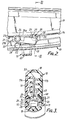
- the sharpener comprises a scabbard 10 and a sharpening device 11.
- the scabbard is shaped to receive a knife 12 having a blade 13 with a cutting edge 14 and a back edge 15 (see Figure 4), and a handle 16.
- the cutting edge 14 has a nearly straight portion leading from the handle to a more highly curved portion which terminates at the tip of the blade.
- the scabbard 10 is formed from any suitable metal, wooden or plastics material, but most conveniently it is moulded from a plastics material. As best seen in Figure 3, the scabbard 10 is of generally rectangular cross-section with two parallel side walls 17a, 17b, a top wall 18, and a bottom wall 19 which follows the curvature of the blade edge i.e. it has a nearly flat portion 19a which is followed by and merges with a more highly curved portion 19b (see Figure 1).
- One side wall 17b is formed with a slot 21 (see Figures 1 to 3) extending along the length thereof.
- a guide rib 45 runs along and parallel to the length of the slot 21 for a purpose to be described below.
- the scabbard 10 is formed with a removable part 46 adjacent the open end of the scabbard 10 and formed by lower parts of the side walls 17, containing an end of the slot 21, and a portion of the bottom wall 19.
- This removable part thus forms a removable U-shaped carrier whose purpose will be described below.
- the carrier 46 may be provided with grooves which engage corresponding rails on the remainder of the scabbard 10 to allow the carrier 46 to be slid into and out of engagement with the remainder of the scabbard 10.
- the sharpening device 11 which is best seen in Figures 2 and 3, includes a carriage 22 mounted within the scabbard and shaped to be slidable in engagement with the inside face of the side wall 17b.
- the carriage 22 is of generally rectangular cross-section and has formed thereon, at the end thereof closer to the entrance to the scabbard 10, a hollow bush 24 formed with a guide slot 24a which cleans the cutting edge 14.
- the bush 24 receives a road 50 (see Figure 2) which engages in the slot 21 and is integral with a slider 23 of the sharpening device so that the carriage 22 is mounted on the slider 23 for pivotal movement about the rod 50.
- An end of the roller 24 remote from the slider 23 engages between two flanges 51 formed on the side wall 17a, which thus guide the carriage 22 in sliding movement.
- the slider 23 engages the outer face of the side wall 17b and extends downwardly before turning under the scabbard 10 to form a handle for moving the carriage 22 along the slot 21.
- the other end of the slider 23 is provided with a boss 20 which also engages in the slot 21 to guide the slider 23.
- a sharpener is located at the end of the carriage remote from the entrance to the scabbard 10 and comprises two or more sharpening plates 27 or the like, which are fixed on the carriage 22 and which extend transversely to the direction of movement of the carriage.
- the plates 27 define between them a V-shaped slot for engagement with the cutting edge 14 of the blade.
- These plates 27 can be of tungsten carbide or other blade sharpening material, or can be replaced by any other suitable form of knife sharpening device.
- a stop 48 Adjacent the plates 27 is a stop 48 which engages the guide rib 45 to limit the pivoting movement of the carriage 22 towards the blade edge 14a.
- a U-shaped spring 28 is secured at one end to the carriage 22 and at its opposite end engages the bottom wall 19 of the scabbard 10 to tend to pivot the sharpener relative to the sldier 23 into contact with the cutting edge 14 of the knife blade.
- a releasable locking device 31 is provided to lock the knife within the scabbard.
- the locking device as seen in Figures 4 to 8, comprises a press-button 32 movable between a raised (see Figure 4) and a depressed (see Figure 7) position in a slot 33, formed in the upper wall 19 of the scabbard 10.
- a plate 34 which is formed integrally with, and depends from, the press-button 32, is provided with a cut-out 35 of inverted L-shape. The plate 34 lies to one side of the knife blade 13.
- a U-shaped slide 36 is guided by flanges 47 formed on the interior of the scabbard 10 (see Figure 6) to be movable horizontally between an extended inoperative position (shown in Figure 7) and a retracted operative position (shown in Figure 4).
- An upper limb 36a of the slide 36 carries a pin 37 intermediate its ends which engages in the cut-out 35 on the plate 34. The free end 36a of this upper limb extends from the scabbard 10, in the extended position of the slide 36.
- a lower limb 36b of the slide 36 carries at its free end a segment-shaped pawl 38 and a cam block 39 which is of generally trapezoidal section (see Figures 5 and 8) and which is received in a complementarily shaped cam slot 40 formed in a lower part of the side wall 17a.
- the slot 40 lies in a plane normal to the plane of the knife blade 13 and to one side of the blade.
- the slot 40 has side walls 40a which, when viewed as in Figures 5 and 8, have a reverse slant relative to the blade 13.
- a torsion spring 41 is carried on a peg 42 formed on the interior of the scabbard 10 and has two arms 41a, 41b, one of which, 41a, engages a lug 43 on the slider 36 to urge the slider 36 towards the extended position and the other of which, 41b, engages a lug 44 on the plate 34 to urge the press-button 32 into the raised position.
- the knife 12 is positioned in the scabbard 10 with the handle 16 forced into the entrance of the scabbard 10 and the back edge 15 of the blade forced into engagement with part of the slide 36 (see Figures 4 and 6) and with a flange 53 provided in the scabbard 10 (see Figure 3).
- the press-button is depressed. This moves the L-shaped cut-out 35 downwardly, thus allowing the pin 37 to enter the horizontal arm of this cut-out 35.
- the slide 36 is thus released for movement by the spring 41 to the extended position, during which movement, the cam block 39 is forced into the slot 40 so moving the pawl 38 out of engagement with the cut-out 14a on the knife blade.
- the free end of the upper limb 36a of the slide is extended out of the scabbard 10, so pushing the handle 16 out of the scabbard to commence removal of the knife from the scabbard 10. This removal is then continued manually to effect complete removal.
- the knife blade is inserted into the scabbard 10.
- the handle engages the projecting end of the upper limb 36a of the slide 36 and continued insertion of the blade 13 causes the slide to be moved against the spring force to the retracted position.
- This movement cams the block 39 out of the slot 40 and so engages the pawl 38 with the cut-out 14a to hold the knife in the scabbard 10.
- the pin 37 is moved into alignment with the vertical limb of the cut-out 35, so allowing the press-button 32 to be raised by the spring 41 and re-triggered for releasing movement.
- the sharpening device 11 when in the retracted position shown in chain line in Figure 1, may either be out of engagement with the blade edge or may be in light engagement with the blade edge. This is determined by appropriate arrangement of the position of the guide rib 45 in relation to the blade edge 14a. When at rest the sharpening device can be located in the position shown in chain line in Figure 1, i.e. adjacent the open end of the scabbard, or at the tip as shown in full line in Figure 1, or at an intermediate position.
- the shape of the sharpening blades 27 may be so arranged that, in one direction of movement, the blades 27 may sharpen theblade 14 and, in the opposite direction, they may hone the blade.
- the correspondence of the shape of the slot 21 with the shape of the cutting edge ensures that both the relatively straight portion of the blade edge and the curved portion of the blade edge are satisfactorily sharpened and also ensures that the sharpening device maintains the same or similar attitude to the blade edge throughout its movement.
- the cutting edge 14 of the blade is sharpened (and honed) while it is still within the scabbard 10. This means that the edge 14 is completely protected during such sharpening so that there is no danger to the user or to surrounding objects during the sharpening action.
- sharpening which may be by one or a number of movements of the sharpening device 11 to-and-fro along the slot, the locking device 31 is released and the blade 14 is withdrawn from the scabbard ready for use.
- the sharpening device 11 If the sharpening device 11 is located at rest near the blade tip, the blade can be inserted into and withdrawn from the scabbard without being sharpened. There is no danger, therefore, of the blade edge 14 being over- sharpened.
- the disposition of the guide rib 45 may be such that, when the sharpening device is in the position shown in chain line in Figure 1, the sharpening device is retracted out of engagement with the blade so that no sharpening is effected by withdrawing the blade from the scabbard.
- the removable scabbard carrier 46 at the open end of the scabbard 10 may be detached from the remainder of the scabbard 10, along with the sharpening device 11, so that the sharpening device 11 can be cleaned and then replaced.
- the carrier maybe only partly disengaged, to an extent necessary to allow the sharpening device 11 to be removed for cleaning.
- the open end of the scabbard is provided with a cuff 43 (see Figure 9) into which the forward end of the handle fits when the knife is fully inserted into the scabbard.
- This cuff may be arranged to locate the knife handle accurately relative to the scabbard. Alternatively, location maybe achieved by locating the knife on a tray, which can be at least partially withdrawn from the scabbard, and then inserting the tray, with the knife blade, into the scabbard.
- a knife wiper can be mounted in the cuff 43 adjacent the open end of the scabbard to wipe the cutting edge as the knife is withdrawn.
- a leather pad or pad of other material can be provided on the scabbard on which the cutting edge can be stropped. Such a leather pad is preferably removable for cleaning or replacement.
- the sharpener has been described as including a sharpening device whose position relative to the blade is the same in each direction of movement, a sharpening device could be provided which has different positions relative to the blade in the two opposite directions of movement of the sharpening device.
- the slider has been described as being movable manually, it will be appreciated that it may be moved by power-operated means.
- the scabbard 10 has been described in relation to a knife having a blade edge 14 of a particular curvature. It will be appreciated that a scabbard can be produced to accommodate any required shape of blade edge, including straight blade edges with the sharpening device passing along the whole blade edge.
Landscapes
- Engineering & Computer Science (AREA)
- Mechanical Engineering (AREA)
- Life Sciences & Earth Sciences (AREA)
- Forests & Forestry (AREA)
- Finish Polishing, Edge Sharpening, And Grinding By Specific Grinding Devices (AREA)
- Fats And Perfumes (AREA)
Applications Claiming Priority (4)
| Application Number | Priority Date | Filing Date | Title |
|---|---|---|---|
| GB848431456A GB8431456D0 (en) | 1984-12-13 | 1984-12-13 | Knife sharpeners |
| GB8431456 | 1984-12-13 | ||
| GB08529042A GB2168275B (en) | 1984-12-13 | 1985-11-26 | Knife sharpeners |
| GB8529042 | 1985-11-26 |
Publications (2)
| Publication Number | Publication Date |
|---|---|
| EP0185483A2 true EP0185483A2 (fr) | 1986-06-25 |
| EP0185483A3 EP0185483A3 (fr) | 1987-01-14 |
Family
ID=26288566
Family Applications (1)
| Application Number | Title | Priority Date | Filing Date |
|---|---|---|---|
| EP85308735A Withdrawn EP0185483A3 (fr) | 1984-12-13 | 1985-12-02 | Aiguisoirs à couteaux |
Country Status (10)
| Country | Link |
|---|---|
| US (1) | US4654968A (fr) |
| EP (1) | EP0185483A3 (fr) |
| AU (1) | AU563262B2 (fr) |
| BR (1) | BR8506233A (fr) |
| CA (1) | CA1234986A (fr) |
| DK (1) | DK580585A (fr) |
| FI (1) | FI854847A7 (fr) |
| GB (1) | GB2168275B (fr) |
| NO (1) | NO854997L (fr) |
| NZ (1) | NZ214558A (fr) |
Cited By (2)
| Publication number | Priority date | Publication date | Assignee | Title |
|---|---|---|---|---|
| EP0243048A1 (fr) * | 1986-04-25 | 1987-10-28 | Fiskars Limited | Aiguisoir pour couteau |
| FR2715340A1 (fr) * | 1994-01-26 | 1995-07-28 | Seb Sa | Fourreau aiguiseur adapté à recevoir un couteau et combinaison d'un tel fourreau et d'un couteau. |
Families Citing this family (19)
| Publication number | Priority date | Publication date | Assignee | Title |
|---|---|---|---|---|
| USD628022S1 (en) * | 1919-02-24 | 2010-11-30 | Bisbell Magnetic Products Limited | Knife blade protector |
| USD625967S1 (en) * | 2009-02-24 | 2010-10-26 | Bisbell Magnetic Products Limited | Knife blade protector |
| AU685322B2 (en) * | 1994-10-05 | 1998-01-15 | Mcpherson's Limited | A blade scabbard |
| CA2201879A1 (fr) * | 1994-10-05 | 1996-04-18 | Mcpherson's Limited | Fourreau de lame |
| AUPP749198A0 (en) * | 1998-12-04 | 1998-12-24 | Mcpherson's Limited | Blade sharpener |
| AU766688B2 (en) * | 1998-12-04 | 2003-10-23 | Mcpherson's Housewares Ip Pty Ltd | Blade sharpener |
| USD424906S (en) * | 1999-02-26 | 2000-05-16 | The Pampered Chef, Ltd. | Sharpener sheath |
| US6224475B1 (en) * | 1999-02-26 | 2001-05-01 | The Pampered Chef, Ltd. | Sharpener sheath |
| GB0029396D0 (en) * | 2000-12-04 | 2001-01-17 | Record Tools Ltd | Chisel scabbard |
| IL148599A0 (en) * | 2002-03-10 | 2002-09-12 | Gotit Ltd | Sharpening apparatus |
| DE20280428U1 (de) * | 2002-03-28 | 2004-11-25 | Wong, Wai Yip | Sicherheitsmesserscheide |
| US7214127B1 (en) | 2006-09-08 | 2007-05-08 | Thompson Timothy L | Butchering tool |
| US9452508B2 (en) | 2013-07-24 | 2016-09-27 | Bar 3 Products Group, Llc | Adjustable knife holder adapted to maintain sharpness of a knife blade and method of manufacturing the adjustable knife holder |
| USD789077S1 (en) * | 2016-01-21 | 2017-06-13 | Lifetime Brands, Inc. | Shears sheath |
| US20190351570A1 (en) * | 2018-05-15 | 2019-11-21 | John Siffermann | Knife and Sheath with Retention System |
| US11376713B1 (en) * | 2021-03-09 | 2022-07-05 | Sharkninja Operating Llc | Knife sharpening systems |
| GB2608099A (en) * | 2021-05-06 | 2022-12-28 | Masson Paul | A sheath for sharpening and retaining a knife |
| US20220395271A1 (en) * | 2021-06-15 | 2022-12-15 | Covidien Lp | Staple cartridge with knife sharpener |
| USD1005818S1 (en) * | 2022-02-10 | 2023-11-28 | Sharkninja Operating Llc | Knife sharpener |
Family Cites Families (10)
| Publication number | Priority date | Publication date | Assignee | Title |
|---|---|---|---|---|
| US2337158A (en) * | 1943-05-07 | 1943-12-21 | Earl L Frank | Knife with built-in sharpener |
| US2416929A (en) * | 1944-11-08 | 1947-03-04 | Bertha M Kjorsvik | Pocketknife |
| US2618057A (en) * | 1951-04-20 | 1952-11-18 | Fred H Gibson | Self-locking knife sheath |
| US2744320A (en) * | 1953-05-19 | 1956-05-08 | Vincent J Palermo | Knife |
| US3339313A (en) * | 1964-06-08 | 1967-09-05 | Carl L Lindhag | Blade honing device |
| US3524570A (en) * | 1968-09-04 | 1970-08-18 | Merle W Seguine | Retainer for sheath knives |
| US3846909A (en) * | 1973-10-29 | 1974-11-12 | R Clarke | Combination of a knife and sharpener |
| FI58270C (fi) * | 1975-08-22 | 1981-01-12 | Wiltshire Cutlery Co Pty | Knivvaessningsanordning |
| AT360862B (de) * | 1977-05-27 | 1980-02-10 | Glock Gaston Ing | Vorrichtung zur loesbaren verbindung eines mit einem handgriff versehenen werkzeuges mit einem behaeltnis |
| GB2111415B (en) * | 1981-11-26 | 1985-07-03 | Wilkinson Sword Ltd | Knife sharpeners |
-
1985
- 1985-11-26 GB GB08529042A patent/GB2168275B/en not_active Expired
- 1985-12-02 EP EP85308735A patent/EP0185483A3/fr not_active Withdrawn
- 1985-12-09 FI FI854847A patent/FI854847A7/fi not_active IP Right Cessation
- 1985-12-10 US US06/807,398 patent/US4654968A/en not_active Expired - Fee Related
- 1985-12-11 AU AU51116/85A patent/AU563262B2/en not_active Ceased
- 1985-12-12 CA CA000497481A patent/CA1234986A/fr not_active Expired
- 1985-12-12 BR BR8506233A patent/BR8506233A/pt unknown
- 1985-12-12 NO NO854997A patent/NO854997L/no unknown
- 1985-12-13 DK DK580585A patent/DK580585A/da not_active Application Discontinuation
- 1985-12-13 NZ NZ214558A patent/NZ214558A/en unknown
Cited By (3)
| Publication number | Priority date | Publication date | Assignee | Title |
|---|---|---|---|---|
| EP0243048A1 (fr) * | 1986-04-25 | 1987-10-28 | Fiskars Limited | Aiguisoir pour couteau |
| FR2715340A1 (fr) * | 1994-01-26 | 1995-07-28 | Seb Sa | Fourreau aiguiseur adapté à recevoir un couteau et combinaison d'un tel fourreau et d'un couteau. |
| EP0665086A1 (fr) * | 1994-01-26 | 1995-08-02 | Seb S.A. | Fourreau aiguiseur adapté à recevoir un couteau et combinaison d'un tel fourreau et d'un couteau |
Also Published As
| Publication number | Publication date |
|---|---|
| BR8506233A (pt) | 1986-08-26 |
| FI854847A0 (fi) | 1985-12-09 |
| FI854847L (fi) | 1986-06-14 |
| AU5111685A (en) | 1986-06-19 |
| NO854997L (no) | 1986-06-16 |
| GB8529042D0 (en) | 1986-01-02 |
| DK580585D0 (da) | 1985-12-13 |
| GB2168275B (en) | 1987-12-23 |
| DK580585A (da) | 1986-06-14 |
| FI854847A7 (fi) | 1986-06-14 |
| GB2168275A (en) | 1986-06-18 |
| AU563262B2 (en) | 1987-07-02 |
| CA1234986A (fr) | 1988-04-12 |
| EP0185483A3 (fr) | 1987-01-14 |
| US4654968A (en) | 1987-04-07 |
| NZ214558A (en) | 1988-03-30 |
Similar Documents
| Publication | Publication Date | Title |
|---|---|---|
| US4654968A (en) | Knife sharpeners | |
| AU2010265834B2 (en) | Blade scabbard, sharpener and sharpening cassette | |
| EP1171257B1 (fr) | Gaine d'aiguisoir | |
| US5036731A (en) | Razor sharpening device | |
| US5431597A (en) | Skate blade edge resurfacer | |
| RU2023574C1 (ru) | Устройство для заточки лезвия | |
| US2601723A (en) | Scraper employing razor blade | |
| US11806839B2 (en) | Knife sharpening systems | |
| US6718639B1 (en) | Self-sharpening utility knife | |
| US5848471A (en) | Windshield wiper reconditioning device | |
| US2237331A (en) | Cutting device | |
| US4974322A (en) | Self sharpening cutting element | |
| US2700819A (en) | Combined knife and sharpener | |
| US1954259A (en) | Shaving device | |
| US1133329A (en) | Razor. | |
| JPS61197152A (ja) | ナイフシヤ−プナ | |
| US2631415A (en) | Safety razor blade holder and support therefor | |
| US1088220A (en) | Razor. | |
| US2641091A (en) | Apparatus for sharpening razor blades and other blades | |
| US2596098A (en) | Lawn mower sharpener | |
| US1230833A (en) | Safety-razor. | |
| US3153307A (en) | Razor blade sharpener | |
| US2921418A (en) | Razor blade sharpener | |
| HK1168328A (en) | Blade scabbard, sharpener and sharpening cassette | |
| GB230641A (en) | Improvements in safety razors |
Legal Events
| Date | Code | Title | Description |
|---|---|---|---|
| PUAI | Public reference made under article 153(3) epc to a published international application that has entered the european phase |
Free format text: ORIGINAL CODE: 0009012 |
|
| AK | Designated contracting states |
Kind code of ref document: A2 Designated state(s): AT BE CH DE FR IT LI LU NL SE |
|
| 17P | Request for examination filed |
Effective date: 19860724 |
|
| PUAL | Search report despatched |
Free format text: ORIGINAL CODE: 0009013 |
|
| AK | Designated contracting states |
Kind code of ref document: A3 Designated state(s): AT BE CH DE FR IT LI LU NL SE |
|
| 17Q | First examination report despatched |
Effective date: 19880315 |
|
| RAP1 | Party data changed (applicant data changed or rights of an application transferred) |
Owner name: FISKARS LIMITED |
|
| STAA | Information on the status of an ep patent application or granted ep patent |
Free format text: STATUS: THE APPLICATION IS DEEMED TO BE WITHDRAWN |
|
| 18D | Application deemed to be withdrawn |
Effective date: 19881026 |
|
| RIN1 | Information on inventor provided before grant (corrected) |
Inventor name: DUNCAN, DAVID STEPHEN Inventor name: GATLEY, DERRICK RAYMOND |