EP0185485A2 - Überwachungsanlagen - Google Patents
Überwachungsanlagen Download PDFInfo
- Publication number
- EP0185485A2 EP0185485A2 EP85308771A EP85308771A EP0185485A2 EP 0185485 A2 EP0185485 A2 EP 0185485A2 EP 85308771 A EP85308771 A EP 85308771A EP 85308771 A EP85308771 A EP 85308771A EP 0185485 A2 EP0185485 A2 EP 0185485A2
- Authority
- EP
- European Patent Office
- Prior art keywords
- image
- charge
- imaging
- rate
- moving object
- Prior art date
- Legal status (The legal status is an assumption and is not a legal conclusion. Google has not performed a legal analysis and makes no representation as to the accuracy of the status listed.)
- Withdrawn
Links
Images

Classifications
-
- G—PHYSICS
- G08—SIGNALLING
- G08B—SIGNALLING SYSTEMS, e.g. PERSONAL CALLING SYSTEMS; ORDER TELEGRAPHS; ALARM SYSTEMS
- G08B13/00—Burglar, theft or intruder alarms
- G08B13/18—Actuation by interference with heat, light, or radiation of shorter wavelength; Actuation by intruding sources of heat, light, or radiation of shorter wavelength
- G08B13/189—Actuation by interference with heat, light, or radiation of shorter wavelength; Actuation by intruding sources of heat, light, or radiation of shorter wavelength using passive radiation detection systems
- G08B13/194—Actuation by interference with heat, light, or radiation of shorter wavelength; Actuation by intruding sources of heat, light, or radiation of shorter wavelength using passive radiation detection systems using image scanning and comparing systems
- G08B13/196—Actuation by interference with heat, light, or radiation of shorter wavelength; Actuation by intruding sources of heat, light, or radiation of shorter wavelength using passive radiation detection systems using image scanning and comparing systems using television cameras
- G08B13/19602—Image analysis to detect motion of the intruder, e.g. by frame subtraction
-
- G—PHYSICS
- G01—MEASURING; TESTING
- G01P—MEASURING LINEAR OR ANGULAR SPEED, ACCELERATION, DECELERATION, OR SHOCK; INDICATING PRESENCE, ABSENCE, OR DIRECTION, OF MOVEMENT
- G01P13/00—Indicating or recording presence, absence, or direction, of movement
-
- G—PHYSICS
- G08—SIGNALLING
- G08B—SIGNALLING SYSTEMS, e.g. PERSONAL CALLING SYSTEMS; ORDER TELEGRAPHS; ALARM SYSTEMS
- G08B13/00—Burglar, theft or intruder alarms
- G08B13/18—Actuation by interference with heat, light, or radiation of shorter wavelength; Actuation by intruding sources of heat, light, or radiation of shorter wavelength
- G08B13/189—Actuation by interference with heat, light, or radiation of shorter wavelength; Actuation by intruding sources of heat, light, or radiation of shorter wavelength using passive radiation detection systems
- G08B13/194—Actuation by interference with heat, light, or radiation of shorter wavelength; Actuation by intruding sources of heat, light, or radiation of shorter wavelength using passive radiation detection systems using image scanning and comparing systems
- G08B13/196—Actuation by interference with heat, light, or radiation of shorter wavelength; Actuation by intruding sources of heat, light, or radiation of shorter wavelength using passive radiation detection systems using image scanning and comparing systems using television cameras
- G08B13/19617—Surveillance camera constructional details
- G08B13/1963—Arrangements allowing camera rotation to change view, e.g. pivoting camera, pan-tilt and zoom [PTZ]
Definitions
- This invention relates to surveillance systems of the type which scan a given field-of-view, can detect a moving object within that field-of-view and produce an image representative of the moving object.
- a passive surveillance system for detecting and for providing an identifiable image of a moving object with respect to the background including:
- the image of a moving object in the viewed scene is held substantially stationary by varying the rate of charge transfer from the photosensitive portion to the storage means and thence to the transport register according to a predetermined sequence in conjunction with the derived electrical signals.
- each device has its own discrete charge transfer rate. Additionally, each imaging device may have a variable charge transfer rate so as to extend the range of possible object speeds which each device may detect.
- the invention described herein is a rotating surveillance system which scans a field-of-view up to 360° in azimuth.
- the system is capable of detecting and 'freezing' the motion of an image of a moving object, for example a target, within the field-of-view so that an operator can identify the moving object on a conventional TV monitor.
- the range of motion which would normally be required to be detected and 'frozen' would fall between the extremes corresponding to an air attack (fast-moving) and a ground attack (slow-moving). It is found that the moving object is frozen with respect to the background which will, in general, remain blurred.
- the invention distinguishes from our UK Patent No. 1523192 which gives only a whole frozen frame and the particular object to be identified will not stand out sufficiently.
- Figure 1 shows a rotatable platform 1 which rotates about a fixed vertical axis 2 in the direction given by arrow 'X'.
- a solid state imaging system shown generally at 3, is mounted on the platform 1 and rotates with it so as to scan a scene in azimuth.
- the system 3 comprises a converging lens system 4 which focusses light from the viewed scene onto an imaging device 5 which is positioned at the focal plane of the lens system 4.
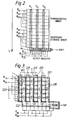
- the imaging device 5 may be a frame transfer charge-cougled device (FTCCD) or an interline transfer charge-coupled device (I T CCD), and the operation of each device is better explained with reference to figures 2 and 3 respectively.
- FCCD frame transfer charge-cougled device
- I T CCD interline transfer charge-coupled device
- the FTCCD has vertical columns V 1 , V 2 and V 3 which form shift registers comprising photosensitive elements isolated from one another by diffusions (the clear areas in figure 2) which the charge carriers are unable to cross.
- the image is produced by the generation of charge over the surface of the device in response to light from the image.
- Each potential well collects the charge carriers in its vicinity so that the stored charge is indicative of the average light falling on the area surrounding the conductor biased to form the potential well.
- the image is broken up into an array of elements which are arranged in rows and columns similar to a television picture.
- image data is transferred from the photosensitive array to a temporary storage array and thence to the output or transport register in response to a composite synchronisation signal.
- Each cycle of the synchronisation signal comprises a number of line synchronisation pulses corresponding to the nunber of rows in the photosensitive array, and a frame synchronisation pulse.
- voltages are selectively applied to 0 ⁇ A1 , 0 ⁇ A2 , 0 ⁇ A3 and 0 ⁇ B1 , 0 ⁇ B2 and 0 ⁇ B3 .
- a charge can be transferred from a potential "well" under a 0 ⁇ A1 electrode by creating a deeper potential well under the 0 ⁇ A2 electrode, after which the potential well under the 0 ⁇ A1 electrode can be eliminated and the "depth" of that under the 0 ⁇ A2 electrode can be reduced.
- charge can be transferred by the application of suitably timed asymmetric drive pulses, all of the same amplitude, to the connections.
- the temporary storage array has been emptied by the line synchronisation pulses and a further set of image-representing charge data therefore can then be transferred from the photosensitive array into the temporary storage array.
- the time between successive frame synchronisation pulses therefore represents the integration time of the charge coupled imager.
- Each line synchronisation pulse feeds a clocking pulse by the 0 ⁇ B1 , 0 ⁇ B2 and 0 ⁇ B3 inputs of the temporary storage array ( Figure 2) so that a row of information is transferred from the temporary storage array into the transport shift register.
- This row of data is clocked out by 0 ⁇ C1 , 0 ⁇ C2 and 0 ⁇ C3 during the interval before the next line synchronisation pulse.
- the generator (not shown) operates in response to each frame synchronisation pulse to transfer data from the photosensitive array into the empty temporary storage array. This is achieved by clocking the 0 ⁇ A1 , 0 ⁇ A2 , 0 ⁇ A3 inputs and the 0 ⁇ B1 , 0 ⁇ B2 , 0 ⁇ B3 inputs in unison with one another.
- 0 ⁇ A1 , 0 ⁇ A2 , 0 ⁇ A3 are clocked during the interval between the frame pulses, that is to say during the integration period of the device, so that the charge pattern follows the image.
- the image is considered to move across the device from the top of the photosensitive array, eventually passing over the temporary storage array, and then off the device altogether.
- the transfer of charge into the storage area is used to correct for image movement, and this charge kept in correct relation with the rost of the image charge pattern.
- An interline transfer charge coupled device as shown in figure 3, can be used instead of the FTCCD of figure 2.
- This device has vertical charge-coupled shift registers 20 to transfer charge into a horizontal output or transport shift register 22.
- the generated charge is stored in adjacent integration areas or sites 26 which can be isolated from the registers by a photogate 28.
- the accumulated charge is then transferred from these integration sites 26 into the columns, to be clocked out, line by line, by opening the photogate.
- the CCD 5 is arranged so that the image traverses the device in the direction of arrow 'Y' and the output or transport register is mounted perpendicular to the plane of the platform 1 but parallel to the axis 2.
- the clocking frequency of the CCD 5 is chosen so that it is directly proportional to the rotational frequency, and compensates for the anticipated speed of a moving object, ie the image of the moving object is held stationary with respect to the device.
- the clocking frequency ie the rate of charge transfer is varied according to a predetermined sequence so that objects travelling at different speeds may be detected.
- the shift registers are clocked in the opposite direction to the direction of rotation ie in the direction of arrow 'Y' so as to compensate for the relative movement between a moving object in the viewed scene and the CCD is achieved as mentioned previously. Therefore, by varying the clocking frequency, when one imaging device is used, a range of possible object speeds can be anticipated. If, on the other hand, more than one imaging device is used (as shown in figure 4), each device is clocked to anticipate one discrete object speed ie the clocking frequency of each device forms a different but constant ratio with the rotational frequency.
- the devices may be arranged to form a vertical bank as shown in figure 4.
- the devices may be arranged in some other way eq around the periphery of the platform 1, depending on the coverage required.
- the clocking frequency is higher than if the object is moving in the direction 'Y', the CCD still being clocked in the direction 'Y'.
- the images of the stationary background are blurred and will average out to a constant 'grey' level, and a moving object travelling through the background at a rate coinciding with the clocking frequency will form an image which appears in sharp contrast on the CCD.
- the clock frequency relating to the CCD concerned may be further tuned to match the object speed perfectly, and the object may then be displayed on a conventional TV monitor for recognition.
- the output register and the vertical column shift registers have to operate at compatible frequencies eg 15625 Hz to empty the output register, and 50 Hz to load lines into the output register.
- the azimuth resolution will be 40 mrads and for a similar elevation resolution, using a 400 horizontal element sensor, the field-of-view will be 9.2°.
- a more versatile method of processing the output information from the CCD is to store it in a limited capacity digital frame store before displaying it as a TV raster.
- the main advantage of doing this is that the object can be further defined by applying suitable algorithms to the stored data.
- the stored information may also be strobed in such a way that any particular sector of 12.3° out of the total field of 360° may be displayed eg a sector containing a moving object.
- the surveillance system described operates in the visible or near infrared region of the electromagnetic spectrum but a 'night-time' capability may be achieved by including suitable image intensifiers.
- the rotation rate of the platform may be checked using an optical pick-off method but this is not essential. However, by accurately controlling the rate of rotation undesirable variations can be removed.
Landscapes
- Physics & Mathematics (AREA)
- General Physics & Mathematics (AREA)
- Engineering & Computer Science (AREA)
- Computer Vision & Pattern Recognition (AREA)
- Transforming Light Signals Into Electric Signals (AREA)
- Closed-Circuit Television Systems (AREA)
- Image Analysis (AREA)
Applications Claiming Priority (2)
| Application Number | Priority Date | Filing Date | Title |
|---|---|---|---|
| GB8431082 | 1984-12-10 | ||
| GB8431082 | 1984-12-10 |
Publications (2)
| Publication Number | Publication Date |
|---|---|
| EP0185485A2 true EP0185485A2 (de) | 1986-06-25 |
| EP0185485A3 EP0185485A3 (de) | 1988-03-16 |
Family
ID=10570931
Family Applications (1)
| Application Number | Title | Priority Date | Filing Date |
|---|---|---|---|
| EP85308771A Withdrawn EP0185485A3 (de) | 1984-12-10 | 1985-12-02 | Überwachungsanlagen |
Country Status (2)
| Country | Link |
|---|---|
| US (1) | US4707735A (de) |
| EP (1) | EP0185485A3 (de) |
Cited By (1)
| Publication number | Priority date | Publication date | Assignee | Title |
|---|---|---|---|---|
| EP0408980A3 (en) * | 1989-07-17 | 1993-01-07 | Siemens Aktiengesellschaft | Passive infrared movement detector with angular resolution |
Families Citing this family (11)
| Publication number | Priority date | Publication date | Assignee | Title |
|---|---|---|---|---|
| DE3750347T2 (de) * | 1986-04-07 | 1994-12-08 | Fuji Photo Film Co Ltd | Festkörper-Farbbildaufnahmegerät. |
| US5990822A (en) * | 1989-04-14 | 1999-11-23 | Honigsbaum; Richard F. | Process and apparatus for finding stealthcraft |
| FR2665600A1 (fr) * | 1990-08-03 | 1992-02-07 | Thomson Csf | Procede de detection pour camera panoramique, camera pour sa mise en óoeuvre, et systeme de veille equipe d'une telle camera. |
| US5155597A (en) * | 1990-11-28 | 1992-10-13 | Recon/Optical, Inc. | Electro-optical imaging array with motion compensation |
| US5692062A (en) * | 1994-10-03 | 1997-11-25 | Recon/Optical, Inc. | Electro-optical imaging array with profiled foward motion compensation |
| US6111523A (en) * | 1995-11-20 | 2000-08-29 | American Traffic Systems, Inc. | Method and apparatus for photographing traffic in an intersection |
| US5948038A (en) * | 1996-07-31 | 1999-09-07 | American Traffic Systems, Inc. | Traffic violation processing system |
| GB9625619D0 (en) * | 1996-12-10 | 1997-01-29 | Barr & Stroud Ltd | Imaging systems |
| US6166373A (en) * | 1998-07-21 | 2000-12-26 | The Institute For Technology Development | Focal plane scanner with reciprocating spatial window |
| US7015954B1 (en) * | 1999-08-09 | 2006-03-21 | Fuji Xerox Co., Ltd. | Automatic video system using multiple cameras |
| US20050138749A1 (en) * | 2003-12-29 | 2005-06-30 | Keck Laura E. | Combination dry and absorbent floor mop/wipe |
Family Cites Families (6)
| Publication number | Priority date | Publication date | Assignee | Title |
|---|---|---|---|---|
| US3851096A (en) * | 1972-11-03 | 1974-11-26 | Texas Instruments Inc | Surveillance system |
| US4064533A (en) * | 1975-10-24 | 1977-12-20 | Westinghouse Electric Corporation | CCD focal plane processor for moving target imaging |
| GB1523192A (en) * | 1977-03-31 | 1978-08-31 | British Aircraft Corp Ltd | Recording images on a record medium |
| US4442457A (en) * | 1981-12-17 | 1984-04-10 | Hughes Aircraft Company | Charge coupled device focal zoom |
| US4396950A (en) * | 1982-02-26 | 1983-08-02 | Honeywell Inc. | CCD Camera |
| GB2157526B (en) * | 1983-05-16 | 1986-08-28 | Barr & Stroud Ltd | Imaging systems |
-
1985
- 1985-12-02 EP EP85308771A patent/EP0185485A3/de not_active Withdrawn
- 1985-12-10 US US06/807,486 patent/US4707735A/en not_active Expired - Fee Related
Cited By (1)
| Publication number | Priority date | Publication date | Assignee | Title |
|---|---|---|---|---|
| EP0408980A3 (en) * | 1989-07-17 | 1993-01-07 | Siemens Aktiengesellschaft | Passive infrared movement detector with angular resolution |
Also Published As
| Publication number | Publication date |
|---|---|
| EP0185485A3 (de) | 1988-03-16 |
| US4707735A (en) | 1987-11-17 |
Similar Documents
| Publication | Publication Date | Title |
|---|---|---|
| US4707735A (en) | Surveillance systems | |
| CA2097179C (en) | Electro-optical imaging array with motion compensation | |
| US5692062A (en) | Electro-optical imaging array with profiled foward motion compensation | |
| US4800435A (en) | Method of driving a two-dimensional CCD image sensor in a shutter mode | |
| EP0776124A3 (de) | Verfahren und Gerät zur Objektabbildung | |
| EP0599470B1 (de) | System für eine Panorama-Kamera | |
| EP0941612A4 (de) | Elektro-optischer bildsensor mit zeitratenbildbewegungskompensation | |
| EP0005972A1 (de) | Infraroteinrichtungen zur Zielentdeckung | |
| WO1999021354A1 (en) | System and method for image motion compensation of a ccd image sensor | |
| GB2302472A (en) | Compensation for relative motion during aerial scanning | |
| US4442457A (en) | Charge coupled device focal zoom | |
| US5309230A (en) | High-sensitivity infrared detector and an infrared camera using such a detector | |
| KR940013150A (ko) | 움직임 벡터 검출 장치 및 고체 촬상 장치 | |
| US4799108A (en) | Method of recording and storing images in rapid sequence | |
| Olson | Image motion compensation with frame transfer CCDs | |
| GB2162019A (en) | Compensating for camera movement | |
| EP0498662B1 (de) | Ein Verfahren zum Auslesen von Signalen aus einer Festkörper-Bildaufnahmevorrichtung | |
| EP0876053B1 (de) | Verfahren zur Steuerung eines Festkörper-Bildsensors | |
| EP0539897A2 (de) | Weitwinkelbild-Erzeugungssystem | |
| EP1313308B1 (de) | Vorrichtung zur elektro-optischen fernerkundung mit bewegungskompensation | |
| US5297762A (en) | Optical navigation sensor with single two-dimensional CCD | |
| JPH0537861A (ja) | 固体撮像装置 | |
| USH1740H (en) | Synchronized rotating prism and CCD electrical readout color camera | |
| JP2000261728A (ja) | 固体撮像装置 | |
| JPS63193678A (ja) | 二次元固体撮像装置 |
Legal Events
| Date | Code | Title | Description |
|---|---|---|---|
| PUAI | Public reference made under article 153(3) epc to a published international application that has entered the european phase |
Free format text: ORIGINAL CODE: 0009012 |
|
| 17P | Request for examination filed |
Effective date: 19851216 |
|
| AK | Designated contracting states |
Kind code of ref document: A2 Designated state(s): DE FR GB |
|
| PUAL | Search report despatched |
Free format text: ORIGINAL CODE: 0009013 |
|
| AK | Designated contracting states |
Kind code of ref document: A3 Designated state(s): DE FR GB |
|
| 17Q | First examination report despatched |
Effective date: 19900920 |
|
| STAA | Information on the status of an ep patent application or granted ep patent |
Free format text: STATUS: THE APPLICATION IS DEEMED TO BE WITHDRAWN |
|
| 18D | Application deemed to be withdrawn |
Effective date: 19910131 |
|
| RIN1 | Information on inventor provided before grant (corrected) |
Inventor name: BUSBY, PETER WILLIAMARMY WEAPONS DIVISION |