EP0185505A2 - Module de séparation d'espaces - Google Patents
Module de séparation d'espaces Download PDFInfo
- Publication number
- EP0185505A2 EP0185505A2 EP85308969A EP85308969A EP0185505A2 EP 0185505 A2 EP0185505 A2 EP 0185505A2 EP 85308969 A EP85308969 A EP 85308969A EP 85308969 A EP85308969 A EP 85308969A EP 0185505 A2 EP0185505 A2 EP 0185505A2
- Authority
- EP
- European Patent Office
- Prior art keywords
- space partition
- partition module
- ceiling
- panel
- module
- Prior art date
- Legal status (The legal status is an assumption and is not a legal conclusion. Google has not performed a legal analysis and makes no representation as to the accuracy of the status listed.)
- Withdrawn
Links
Images


Classifications
-
- E—FIXED CONSTRUCTIONS
- E04—BUILDING
- E04B—GENERAL BUILDING CONSTRUCTIONS; WALLS, e.g. PARTITIONS; ROOFS; FLOORS; CEILINGS; INSULATION OR OTHER PROTECTION OF BUILDINGS
- E04B2/00—Walls, e.g. partitions, for buildings; Wall construction with regard to insulation; Connections specially adapted to walls
- E04B2/74—Removable non-load-bearing partitions; Partitions with a free upper edge
- E04B2/7407—Removable non-load-bearing partitions; Partitions with a free upper edge assembled using frames with infill panels or coverings only; made-up of panels and a support structure incorporating posts
- E04B2/7416—Removable non-load-bearing partitions; Partitions with a free upper edge assembled using frames with infill panels or coverings only; made-up of panels and a support structure incorporating posts with free upper edge, e.g. for use as office space dividers
-
- A—HUMAN NECESSITIES
- A47—FURNITURE; DOMESTIC ARTICLES OR APPLIANCES; COFFEE MILLS; SPICE MILLS; SUCTION CLEANERS IN GENERAL
- A47B—TABLES; DESKS; OFFICE FURNITURE; CABINETS; DRAWERS; GENERAL DETAILS OF FURNITURE
- A47B87/00—Sectional furniture, i.e. combinations of complete furniture units, e.g. assemblies of furniture units of the same kind such as linkable cabinets, tables, racks or shelf units
-
- A—HUMAN NECESSITIES
- A47—FURNITURE; DOMESTIC ARTICLES OR APPLIANCES; COFFEE MILLS; SPICE MILLS; SUCTION CLEANERS IN GENERAL
- A47B—TABLES; DESKS; OFFICE FURNITURE; CABINETS; DRAWERS; GENERAL DETAILS OF FURNITURE
- A47B2200/00—General construction of tables or desks
- A47B2200/0066—Workstations
- A47B2200/0067—Enclosure type with computer
- A47B2200/007—Enclosure type with computer with incorporated desk and chair
-
- A—HUMAN NECESSITIES
- A47—FURNITURE; DOMESTIC ARTICLES OR APPLIANCES; COFFEE MILLS; SPICE MILLS; SUCTION CLEANERS IN GENERAL
- A47B—TABLES; DESKS; OFFICE FURNITURE; CABINETS; DRAWERS; GENERAL DETAILS OF FURNITURE
- A47B2200/00—General construction of tables or desks
- A47B2200/0066—Workstations
- A47B2200/0067—Enclosure type with computer
- A47B2200/0071—Booth like
-
- E—FIXED CONSTRUCTIONS
- E04—BUILDING
- E04B—GENERAL BUILDING CONSTRUCTIONS; WALLS, e.g. PARTITIONS; ROOFS; FLOORS; CEILINGS; INSULATION OR OTHER PROTECTION OF BUILDINGS
- E04B2/00—Walls, e.g. partitions, for buildings; Wall construction with regard to insulation; Connections specially adapted to walls
- E04B2/74—Removable non-load-bearing partitions; Partitions with a free upper edge
- E04B2002/7483—Details of furniture, e.g. tables or shelves, associated with the partitions
Definitions
- the present invention relates to partition arrangements for open office space, and in particular to a space partition module.
- partition panels are interconnected to form a series of walls that define separate cubicles.
- wall partitions do not extend to the ceiling, but have a height that is slightly above the line of sight of the average individual, so that each office cubicle has some degree of privacy.
- the sense of "privacy" is ° greatly reduced.
- the common ceiling that is shared by prior office cubicles normally contains all of the room's overhead lighting, as well as the room's heating and cooling. Hence, a flickering overhead light, or a whistling air duct will be sensed by the workers in many, if not all of the office cubicles in the room. Such factors do not support a feeling of privacy within the office cubicle.
- the large gap or space which normally exists between the top of the wall partitions and the ceiling of the room permits noises, odors, and other distracting stimuli to be readily transmitted between neighbouring office cubicles.
- an average height worker can look over the typical, sixty-five inch (1.65m) wall partitions, and peer into any particular office cubicle, without going through the designated entrance. Those workers that are above average height have no trouble whatsoever in looking over sixty-five inch (1.65m) wall partitions, and furthermore, their heads are readily visible to the occupants of the office cubicles as these individuals pass by.
- a space partition module is characterised by first and second sidewall panels positioned in a generally vertical, oppositely facing orientation, and having upper, lower and side edges; means for supporting the first and second sidewall panels in a generally parallel, spaced apart, and freestanding condition; and a ceiling having opposite end edges connected with the upper edges of the first and second sidewall panels, and extending therebetween to form a canopy which, in conjunction with said first and second sidewall panels, defines a workstation within the open space.
- a space partition module for subdividing an open office space in a building envelope, which is defined by a building ceiling, a building floor having a predetermined area and perimeter, and fixed building walls having a predetermined height is characterised by first and second sidewall panels positioned in a generally vertical, oppositely facing orientation; said first and second sidewall panels having upper edges, lower edges, and side edges, with said lower edges extending along the building floor; means for supporting said first and second sidewall panels in a generally parallel, spaced apart, and freestanding condition; a ceiling having opposite end edges connected with the upper edges of said first and second sidewall panels, and spanning said first and second sidewall panels without any intermediate support; said ceiling being supported by said first and second sidewall panels being spaced apart and arranged in a manner that defines an interior area and a perimeter which are substantially less than the area and the perimeter of the open office space in the building envelope, whereby said space partition module can be freely positioned on the building floor at any desired location; said ceiling forming a canopy with sufficient
- the invention thus provides a unique space partition module that creates private, three-dimensional work stations within an open office plan.
- the office module includes two sidewall panels, which are positioned in a generally vertical, oppositely facing orientation, and are supported in a spaced apart, freestanding condition, i.e., without attachment to the room ceiling or walls.
- the office module is also preferably self-supporting, so that it need not be fastened to the floor of the building.
- a ceiling may include a central aperture through which light in the open office space can be transmitted into the interior of the space partition module.
- the ceiling may also have opposite end edges connected with the upper edges of the sidewall panels, and spans between then without any intermediate support.
- a central aperture through which light in the open office space can be transmitted into the interior of the space partition module may be provided.
- An overhead light panel may also be provided which is shaped for reception in the central aperture of the ceiling and may also include means for emitting light into the interior of the space partition module.
- a ceiling may also, if desired, comprise a panel having a substantially rectangular plan shape.
- the office module has a height and girth which are substantially smaller than the respective dimensions of the open office space which is to be divided, so that the office module can be easily transported and placed in any desired location within the room.
- the ceiling is located well above the head height of the average worker, and forms a canopy, which in conjunction with the sidewall panels, defines a three-dimensional work station that has a degree of privacy for more efficient work performance, without evoking a sense of claustrophobia.
- Cover panels are preferably provided to interconnect the side panels and the ceiling, and are inclined inwardly to provide a smooth transition therebetween.
- a privacy panel may be connected with a side edge of one of the sidewall panels to partially or completely close off one of the open ends of the office module to create a private work area, and also to provide lateral stability.
- a generally L-shaped reception area panel may also be connected with a side edge of one of the sidewall panels to provide extra stability to the module, and also to form a two-dimensional, semi-private reception area adjacent to the three-dimensional work station.
- the first and second sidewall panels and/or the ceiling may include at least one closed conduit therein. Means may also be provided for communicating the said conduit with overhead utilities in the open office space, or with floor mounted utilities in the said open office space.
- a desirable object of the present invention is to provide a unique space partition module that is particularly designed for use in. open office layouts.
- the office module gives workers the sensation of having their very own private room, without causing claustrophobia, thereby alleviating "close work" fatigue.
- the office module is a sturdy, freestanding and self-supporting unit, and can be easily positioned at any desired location within the room. Since each office module has its own walls and ceiling, the transmission of sound, light, odors and other distracting stimuli between neighbouring offices can be greatly reduced.
- the modules have maximum sound absorption in a particular direction of orientation, so that multiple modules can be arranged to achieve the desired degree of audio isolation. Sound making may also be provided in each module to alleviate the disruptive effect of external conversations, and other noises.
- the first and second sidewalls, the core panels, the ceiling, the privacy panel and the reception area panel have an acoustic interior side for noise abatement.
- Each office module can have its own controlled lighting to suit the specific task being performed in the work station. Furthermore, a greater degree of air circulation and temperature control can be achieved in each separate work station.
- the present invention is particularly adapted for renovating old buildings, since utilities such as power lines, telephone lines, heating and cooling facilities, and the like can be brought to the work stations through the sidewalls and ceiling of the module, thereby avoiding the need to remove and/or replace existing building facilities.
- the office module is also modular in construction, so that a plurality of units can be interconnected to form an integrated office system in which the various modules are mutually oriented in a predetermined pattern in accordance with the task to be performed, so as to achieve maximum work efficiency.
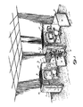
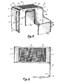
- the reference numeral 1 ( Figure 1) generally designates a space partition module embodying the present invention.
- the office module 1 includes two sidewall panels 2 and 3, which are positioned in a generally vertical, oppositely facing orientation, and are supported in a mutually spaced apart and freestanding condition.
- a ceiling 4 has opposite end edges connected with the upper edges of sidewall panels 2 and 3, and extends therebetween without any intermediate support.
- the office module 1 has a height and a girth which are substantially smaller than the respective dimensions of the open office space, so that the office module 1 can be easily transported and placed at any desired location within the room.
- the ceiling 4 is located well above the head height of the average worker, and forms a canopy, which in conjunction with the sidewall panels 2 and 3, defines a three-dimensional work station that has a degree of privacy for more efficient work performance, without evoking a sense of claustrophobia.
- the sidewall panels 2 and 3 are flat, have a generally rectangular plan shape, and include side edges 10 and 11, and upper and lower edges 12 and 13 respectively.
- the lower edges 13 of the sidewall panels 2 and 3 abut the floor of the open office space, and support the office module 1 thereon.
- the sidewall panels 2 and 3 are held effect and self-supported or freestanding through their connection to ceiling panel 4. Laterally extending feet (not shown) may be attached to the sidewall panels 2 and 3 to provide additional stability.
- the sidewall panel 2 includes a rectangularly shaped aperture or window 14 that is designed to provide light and visual communication between adjacent offices, when such communication is desired.
- the window 14 may assume different shapes, sizes, and positions, and that the illustrated embodiment is merely exemplary of one suitable window configuration.
- the longitudinal axis of the illustrated window 14 is oriented in a vertical direction.
- the window 14 is positioned adjacent to the forward edge 10 of the sidewall panel 2, and may include a panel of glass, or other suitable transparent material, to reduce the transmission of noise and odors between offices.
- the sidewall panels 2 and 3 preferably have a height and width in the range of 5-7 feet (1.52m - 2.13m).
- One particular example of the sidewall panels 2 and 3 has a height of approximately 75 inches (190cm), and a width of approximately 75 inches (190cm).
- the ceiling 4 illustrates in Figures 1 - 13 is in the nature of a panel, having a generally rectangular plan configuration, with opposite side edges 22 and 23, and end edges 24 and 25, and is attached to the sidewall panels 2 and 3 by a pair of cove panels 20 and 21.
- the cove panels 20 and 21 have their opposite side edges connected with the upper edges 12 of the sidewall panels 2 and 3, and the end edges 24 and 25 of ceiling panel 4, and are inclined inwardly towards the ceiling panel 4.
- the cove panels 20 and 21 have a generally arcuate, end elevational shape, in the nature of one quarter of a cylinder.
- the cove panels 20 and 21 provide a smooth transition between the sidewall panels 2 and 3 and the ceiling panel 4, and assist in creating a canopy effect for the office module 1.
- One particular example of the cove panels 20 and 21 has a length of approximately 75 inches (190cm), and a radius of approximately 16 inches (4lcm).
- the ceiling panel 4 ( Figures 2 and 3) is flat, and preferably includes a central aperture or window 30 through which air and light in the open office space can be transmitted into the interior of the office module 1.
- the illustrated ceiling window 30 has a generally rectangular plan configuration, and is rather large, encompassing a major portion of the entire surface of the ceiling panel 4.
- the ceiling window 30 also permits overhead fire sprinkling systems in the room to introduce water to the interior of office module 1 in the event of a fire.
- On particular example of ceiling panel 4 has a width of approximately 75 inches (190cm), and a length of approximately 88 inches (224cm).
- a grid-like light deflector panel 33 is mounted in the window 30 of the ceiling panel 4.
- the light deflector 33 is of the open grid type so that light, water and air can pass freely therethrough.
- the light deflector 33 is designed to diffuse incoming overhead light to alleviate shadows and/or any glare that might appear on work surfaces, video display tubes (VDT), and the like.
- An additional light source such as the light units 34 illustrated in Figures 8 - 10, can also be mounted in the window 30 to provide an additional source of light for the office module 1.
- the office module 1 preferably includes at least one laterally extending panel connected with one of the sidewall panels 2 and 3, in the nature of an outrigger panel, to improve the lateral stability of the module.
- the outrigger panel is positioned in a non-parallel relationship with the sidewall panels 2 and 3, and has a lower edge which is supported on the floor of the building.
- Two different types of outrigger panels are disclosed in the present application, and comprise a reception area panel 40 ( Figure 1) and a privacy panel 50.
- the reception area panel 4,0 is attached to a side edge 10 or 11 of one of the sidewall panels 2 and 3.
- the reception area panel 40 has a generally L-shaped plan configuration.
- the reception area panel 40 is connected to the forward edge 10 of the sidewall panel 3, and provide extra lateral stability to the office module 1, and also forms a two-dimensional, semi-private reception area, similar to a curtilage, adjacent to the three-dimensional work station.
- the , reception area panel 40 includes a flat side section 41, a flat end section 42, and an arcuate intermediate section 43.
- the reception area panel 40 is generally chest to shoulder high, and in this example, includes an arcuate, upwardly oriented transition section 44 that blends smoothly into the forward edge 10 of sidewall panel 3.
- One particular reception area panel 40 has a height of approximately 55 inches (1.40m), and the side section 41 has a length of around 75 inches (1.90m), with the end section 42 approximately 70-90 inches (1.52 - 2.27m) long.
- a privacy panel 50 is attached to the rear edge of the sidewall panel 3, and extends laterally across the rear end of the office module 1 to form a closed corner area.
- the illustrated privacy panel 50 extends approximately halfway across the open, rear end of the office module 1, and has a height approximately three-quarters of the height of the office module.
- the privacy panel 50 has a flat lower section 51, and an arcuate, inwardly inclined upper section 52.
- One particular privacy panel 50 has a width of approximately 60 inches (1.52m), and a height of around 71 inches (1.80m).
- the privacy panel 50 may have different widths and heights, and may extend any length across the open, rear end of office module 1, including completely across the open end to maximize privacy.
- the office module 1 preferably includes acoustical characteristics which provide a very quiet, soundproof work space.
- the sidewall panels 2 and 3, the cove panels 20 and 21, the ceiling panel 4, the reception area panel 40, and the privacy panel 50 each have a hard exterior surface that reflects ambient sounds emanating from the open office, and a soft, sound absorbent interior surface that absorbs sound, and abates the transmission of noise generated from within the office module to neighbouring work stations.
- the area at which the privacy panel 50 abuts the sidewall panel 3 provides an excellent area to locate a work surface, such as the area shown in broken lines in Figure 6, and noted by the reference numeral 55.
- the forward right-hand corner of the work surface 55 provides a very good area in which to locate a telephone. This area is in the nature of a phone booth, and provides improved privacy, and reduced sound transmission.
- the reception area panel 40 creates a semi-private reception area, which is also shown in broken lines in Figure 6, and is noted by the reference numeral 56.
- the office module 1 includes two entrance and exit areas 57 and 58 through which workers can access the work station.
- the interconnection of the adjacent panel portions of the office module 2 are preferably achieved by hinges 60, which permit the unit to be folded up for storage and/or transportation.
- the office module 1 illustrated in Figure 4 includes a utility duct 62, which can be used to provide electrical power, telephone lines, air conditioning, and other utilities to the office module.
- the utility duct 62 has a generally vertical section 63 which extends through the interior of sidewall panel 2 and the cove panel 20, and a generally horizontal section 64 which extends through the interior of ceiling panel 4.
- the opposite sidewall and cove panels 3 and 21 have an identical vertical duct section (not shown) which communicate with the ceiling duct 64, so as to form a continuous utility duct which can be used not only to service the office module 1, but also to connect the utilities with adjacent office modules.
- the utility duct 62 can supply conditioned or recirculated air to a register (not shown) in the ceiling panel 4, so that the work station has independent temperature control.
- An auxiliary air-conditioner unit (not shown) can also be mounted in the ceiling panel 4 to provide extra cooling for sensitive machinery, such as computers, and the like.
- the flowing, curved lines of the office module 1 are achieved through an upper section 52 of the privacy panel 50, the curved corner portion 43 of the reception area panel 40, and the cove panels 20 and 21.
- This arcuate overall shape makes the office module 1 aesthetically pleasing, and gives the office module a sense of roominess far beyond its actual dimensions.
- a plurality of office modules 1 can be arranged in various configurations to achieve an integrated, overall office plan or scheme, and maximize efficient use of floor space.
- the office modules 1 can be arranged so as to create a common, private area 65, which can be used for conferences, library facilities, secretarial services, or the like.
- Figure 11 shows four office modules 1 in a laterally staggered, or overlapping configuration, which creates an inner corridor or hallway 66.
- the reference numeral la ( Figure 12) designates another embodiment of the present invention. Since the office module la is similar to the previously described office module 1, similar parts appearing in Figures 1 - 11 and 12 respectively are represented by the same, corresponding reference numeral, except for the suffix "a" in the numerals of the latter.
- the office module la does not include separate cove panels, a reception area panel, or a privacy panel, but is otherwise identical to the previously described office module 1.
- the reference numeral lb ( Figure 13) designates yet another embodiment of the present invention. Since the office module lb is similar to the previously described office module 1, similar parts appearing in Figures 1 - 11 and 13 respectively are represented by the same, corresponding reference numeral, except for the suffix "b" in the numerals of the latter. In the office module lb, the cove panels 20b and 21b are generally trapezoidal in shape, and the ceiling panel 4b does not include a window.
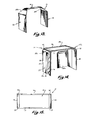
- the reference numeral lc ( Figures 14 - 18) designates yet another embodiment of the present invention. Since the office module lc is similar to the previously described office module 1, similar parts appearing in Figures 1 - 11 and 14 - 18 respectively are represented by the same, corresponding reference numeral, except for the suffix "c" in the numerals of the latter.
- the ceiling 4c comprises a pair of straight, horizontally oriented posts or struts 70 and 71, which have their ends connected with the upper side edges of cove panels 20c and 21c.
- the window 30c has a rectangular plan shape, and is formed between the inside edges of the struts 70 and 71, and the upper edges of cove panels 20- and 21c.
- the struts 70 and 71 form only the sides of the window 30c.
- the struts 70 and 71 are straight and rigid, and laterally interconnect the sidewall panels 2c and 3c to support the same in a freestanding or self-supporting condition, as does the ceiling panel 4 in the office module 1.
- the struts 70 and 71 are tubular, with a hollow interior to form enclosed channels or ducts through which utilities may be provided to the office module lc.
- the struts 70 and 71 have a rectangular lateral cross-sectional shape, and in one particular example, have a length of approximately 88 inches (2.24m), a width in the nature of 3 to 4 inches (7.6 - 10.2cm), and a thickness of approximately 2-3 inches (5.1 - 7.6cm).
- the cove panels 20c and 21c of the office module lc have a three-piece construction, comprising a pair of curved frame sections 72 and 73, and a centre panel 74 connected therebetween.
- the cove frame sections 72 and 73 preferably have a hollow tubular construction that is similar in lateral cross-sectional shape to that of the struts 70 and 71, so that these members interconnect in a telescoping fashion, and form continuous utility ducts along both the front and the rear of the office module lc.
- the centre panel 74 is preferably detachably connected with the interior side edges of the cove frame sections 72 and 73, and the upper edges 12 of the sidewall panels 2 and 3 by suitable fasteners, such as screws, clips, or the like, so that the centre panel 74 can be removed from the office module lc as illustrated in Figures 16 - 18.
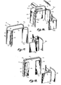
- the sidewall panels 2c and 3c of the office module lc have a four-piece construction, comprising a pair of straight, vertically oriented frame sections 75 and 7.6, and a two-piece centre panel 77 connected therebetween.
- the sidewall frame sections 75 and 76 preferably have a hollow, tubular construction, which is similar in lateral cross-sectional shape to that of both the struts 70 and 71, and the cove frame sections 72 and 73, so that these members are interconnected in a telescoping fashion, and form two continuous utility ducts along both the front and the rear of the office module lc.
- the struts 70 and 71 in conjunction with the cove frame sections 72 and 73 and sidewall frame sections 75 and 76 form two, rigid arches at the front and rear of office module lc, which define the structural skeleton of the office module.
- the sidewall centre panel 77 comprises a pair of rectangular panels 78 and 79 positioned side-by-side, having their adjacent, inner edge 80 pivotally interconnected by a hinge, or the like, and their opposite, outer edges pivotally connected with an adjacent one of the sidewall frame sections 75 and 76 by a hinge, or other similar device.
- the privacy panel 50c and reception area panel 40c of the office module lc are also detachably connected to the office module, so that they can be readily removed for storage and/or transport.
- the cove centre panels 74, the privacy panel 50c, and the reception area panel 40c are first detached and removed from the office module, lc, as shown in Figure 16.
- the two sidewall centre panels 78 and 79 are then rotated inwardly, along their adjacent inner edges, as shown in Figure 17, until the office module lc assumes the fully folded condition illustrated in Figure 18.
- the office modules, 1, la, lb and lc all provide a unique, space partition module that creates private, three-dimensional work stations within an open office space.
- Each office module personalizes the work station, and provides the worker with the sensation of having his or her very own private room, even within extremely large open office plans.
- Each office module includes a private area in which work can be performed efficiently and without distractions, as well as open areas to avoid evoking a sense of claustrophobia.
- the office module is aesthetically pleasing, and can be arranged in many different manners to achieve a particular office configuration.
Landscapes
- Engineering & Computer Science (AREA)
- Architecture (AREA)
- Physics & Mathematics (AREA)
- Electromagnetism (AREA)
- Civil Engineering (AREA)
- Structural Engineering (AREA)
- Building Environments (AREA)
- Conveying And Assembling Of Building Elements In Situ (AREA)
- External Artificial Organs (AREA)
Applications Claiming Priority (2)
| Application Number | Priority Date | Filing Date | Title |
|---|---|---|---|
| US680282 | 1984-12-10 | ||
| US06/680,282 US4715154A (en) | 1984-12-10 | 1984-12-10 | Space partition module |
Publications (2)
| Publication Number | Publication Date |
|---|---|
| EP0185505A2 true EP0185505A2 (fr) | 1986-06-25 |
| EP0185505A3 EP0185505A3 (fr) | 1988-07-06 |
Family
ID=24730469
Family Applications (1)
| Application Number | Title | Priority Date | Filing Date |
|---|---|---|---|
| EP85308969A Withdrawn EP0185505A3 (fr) | 1984-12-10 | 1985-12-10 | Module de séparation d'espaces |
Country Status (6)
| Country | Link |
|---|---|
| US (1) | US4715154A (fr) |
| EP (1) | EP0185505A3 (fr) |
| JP (1) | JPS61137971A (fr) |
| AU (1) | AU5041985A (fr) |
| CA (1) | CA1252978A (fr) |
| ES (1) | ES296367Y (fr) |
Cited By (5)
| Publication number | Priority date | Publication date | Assignee | Title |
|---|---|---|---|---|
| GB2216919A (en) * | 1988-04-08 | 1989-10-18 | Stc Plc | Telephone kiosk with hinged panel for access to electronic equipment |
| GB2265396A (en) * | 1992-03-26 | 1993-09-29 | Victor Brian Pye | Mobile workstation |
| FR2697733A1 (fr) * | 1992-11-09 | 1994-05-13 | Productions Metalliques Tubula | Agencement de mobilier avec amortissement phonique, notamment de tables et de sièges pour collectivités. |
| GB2308296A (en) * | 1995-12-21 | 1997-06-25 | Okamura Corp | Multimedia tower and booth |
| AT523390B1 (de) * | 2020-02-28 | 2021-08-15 | Oberascher Manuel | Raumtrennsystem |
Families Citing this family (46)
| Publication number | Priority date | Publication date | Assignee | Title |
|---|---|---|---|---|
| US4856242A (en) * | 1984-12-10 | 1989-08-15 | Steelcase Inc. | Space partition arrangement |
| US4843788A (en) * | 1988-01-11 | 1989-07-04 | Moduform, Inc. | Modular seclusion room |
| DE3917954A1 (de) * | 1989-06-02 | 1990-12-06 | Dornier Gmbh | Kabine |
| US5511348A (en) | 1990-02-14 | 1996-04-30 | Steelcase Inc. | Furniture system |
| US6003275A (en) | 1990-02-14 | 1999-12-21 | Steelcase Development Inc. | Furniture system |
| US6134844A (en) | 1990-02-14 | 2000-10-24 | Steelcase Inc. | Method and apparatus for displaying information |
| US6170200B1 (en) | 1990-02-14 | 2001-01-09 | Steelcase Development Inc. | Furniture system |
| US5282341A (en) * | 1992-01-10 | 1994-02-01 | Steelcase Inc. | Dynamic workspace module |
| US5461916A (en) | 1992-08-21 | 1995-10-31 | Nippondenso Co., Ltd. | Mechanical force sensing semiconductor device |
| US5651219A (en) * | 1993-10-29 | 1997-07-29 | Steelcase Inc. | Dynamic workspace module |
| DE4414389A1 (de) * | 1994-04-26 | 1995-11-02 | Gemuenden Manfred | Ein wandelbares Büro |
| JP2789451B2 (ja) * | 1996-05-21 | 1998-08-20 | 株式会社岡村製作所 | 視聴覚ブース |
| US6540094B1 (en) | 1998-10-30 | 2003-04-01 | Steelcase Development Corporation | Information display system |
| US6374547B1 (en) | 1998-10-30 | 2002-04-23 | Steelcase Development Inc. | Workstation |
| US6971197B1 (en) | 1998-10-30 | 2005-12-06 | Steelcase Development Corporation | Display board system |
| US6892650B2 (en) | 2001-06-22 | 2005-05-17 | Steelcase Development Corporation | Movable display support system |
| US6463701B1 (en) | 1998-10-30 | 2002-10-15 | Steelcase Development Corporation | Work environment |
| US6931795B1 (en) | 1998-10-30 | 2005-08-23 | Steelcase Development Corporation | Utility distribution system |
| US6272779B1 (en) | 1998-10-30 | 2001-08-14 | Steelcase Development Inc. | Display board system |
| US6647652B1 (en) | 1998-10-30 | 2003-11-18 | Steelcase Development Inc. | Display board system |
| US6279761B1 (en) | 1999-03-01 | 2001-08-28 | Steelcase Development Inc. | Information display system |
| US6941691B2 (en) | 2000-09-25 | 2005-09-13 | Steelcase Development Corporation | Display board system |
| US6817478B2 (en) | 2001-05-31 | 2004-11-16 | Frank Venegas, Jr. | Modular office furniture |
| US20030002692A1 (en) * | 2001-05-31 | 2003-01-02 | Mckitrick Mark A. | Point sound masking system offering visual privacy |
| US6739096B2 (en) | 2001-06-22 | 2004-05-25 | Steelcase Development Corporation | Movable office support system |
| US7117802B2 (en) | 2002-09-06 | 2006-10-10 | Hoke Jr Gary Dale | Cubicle shield |
| US7032523B2 (en) | 2003-04-03 | 2006-04-25 | Steelcase Development Corporation | Workstation with a moveable apparatus |
| DE20313111U1 (de) * | 2003-08-26 | 2005-01-05 | Dauphin Entwicklungs- Und Beteiligungs-Gmbh | Arbeitsraum-Modul |
| US7677182B2 (en) | 2004-05-27 | 2010-03-16 | Steelcase Development Corporation | Two person work environment |
| US20070283631A1 (en) * | 2006-06-07 | 2007-12-13 | Jay Grandin | Workspace Dividing System |
| NZ576211A (en) * | 2006-10-06 | 2012-02-24 | Formway Furniture Ltd | Workstation screen with transparent and opaque regions |
| US8621787B2 (en) * | 2010-01-25 | 2014-01-07 | Ironstate Development, Llc | Prefabricated building modules for multi-unit housing |
| JP2014037671A (ja) * | 2012-08-10 | 2014-02-27 | Itoki Corp | ブース装置及びその天井部ユニット |
| US9603457B2 (en) | 2013-05-31 | 2017-03-28 | Steelcase Inc. | Lounge assemblies for supporting portable electronics devices |
| JP6292823B2 (ja) * | 2013-11-01 | 2018-03-14 | 株式会社岡村製作所 | 間仕切り装置 |
| JP2015085107A (ja) * | 2013-11-01 | 2015-05-07 | 株式会社岡村製作所 | 什器システム |
| USD758777S1 (en) | 2015-02-13 | 2016-06-14 | Steelcase, Inc. | Personal workspace furniture |
| USD778653S1 (en) | 2015-02-13 | 2017-02-14 | Steelcase Inc. | Table top |
| USD758115S1 (en) | 2015-02-13 | 2016-06-07 | Steelcase, Inc. | Personal workspace furniture |
| US9622570B1 (en) | 2015-02-13 | 2017-04-18 | Steelcase Inc. | Personal workspace assembly |
| USD758776S1 (en) | 2015-02-13 | 2016-06-14 | Steelcase, Inc. | Personal workspace furniture |
| US20160374468A1 (en) | 2015-06-29 | 2016-12-29 | Ipic-Gold Class Entertainment, Llc | Theater Seating |
| USD895988S1 (en) * | 2018-06-29 | 2020-09-15 | Senator International Limited | Screen |
| JP7010394B2 (ja) * | 2021-01-13 | 2022-01-26 | コクヨ株式会社 | ブース |
| US12224069B2 (en) | 2021-03-29 | 2025-02-11 | International Business Machines Corporation | Workstation assignment |
| WO2023048938A1 (fr) | 2021-09-22 | 2023-03-30 | Steelcase Inc. | Ensemble de panneaux et accessoires et procédé d'utilisation et d'assemblage de ceux-ci |
Family Cites Families (40)
| Publication number | Priority date | Publication date | Assignee | Title |
|---|---|---|---|---|
| CA613513A (en) * | 1961-01-31 | Beardsworth George | Partitions | |
| US2608726A (en) * | 1952-09-02 | Collapsible tcoy building | ||
| US2089059A (en) * | 1935-05-24 | 1937-08-03 | Bertron G Harley | Diner |
| US2751635A (en) * | 1950-03-09 | 1956-06-26 | Thomas C Donnahue | Portable prefabricated shelter |
| BE551867A (fr) * | 1955-10-18 | |||
| US3550601A (en) * | 1968-12-04 | 1970-12-29 | Donald F Peters | Portable collapsible child's play enclosure |
| US3611907A (en) * | 1969-10-16 | 1971-10-12 | Industrial Acoustics Co | Ventilated portable structure |
| US3564787A (en) * | 1969-12-03 | 1971-02-23 | Raymond Sherman | Modular design block |
| FR2095412A5 (fr) * | 1970-03-02 | 1972-02-11 | Berce Jacques | |
| US3828492A (en) * | 1970-05-06 | 1974-08-13 | J Borgos | Structural module |
| US3683100A (en) * | 1970-11-04 | 1972-08-08 | John V Deal | Modular wall and ceiling system |
| US3807105A (en) * | 1971-05-10 | 1974-04-30 | Rudkin Wiley Corp | Modular building units |
| US3719768A (en) * | 1971-05-27 | 1973-03-06 | American Modular Syst Designs | Construction panel |
| US3838545A (en) * | 1971-06-09 | 1974-10-01 | E Kump | Modular environmental space module |
| US3774357A (en) * | 1971-11-23 | 1973-11-27 | Misterhouse Toys Inc | Children{40 s play garage with self-contained storage compartment |
| US3802133A (en) * | 1972-05-30 | 1974-04-09 | J Gregory | Building structure |
| US3871146A (en) * | 1972-07-28 | 1975-03-18 | Trebron Holdings Ltd | Constant module system |
| US3865429A (en) * | 1973-05-18 | 1975-02-11 | Joseph K Barker | Portable collapsible shelter |
| US3841037A (en) * | 1973-07-05 | 1974-10-15 | L Clark | Portable window-service counter unit |
| US3863404A (en) * | 1973-08-09 | 1975-02-04 | Building Components Research I | Building Construction |
| US3916972A (en) * | 1973-09-28 | 1975-11-04 | Steelcase Inc | Partition system |
| US3848375A (en) * | 1973-10-03 | 1974-11-19 | B White | Portable furniture device |
| US3905167A (en) * | 1973-11-09 | 1975-09-16 | Berne A Watkins | Modularized building system |
| GB1460111A (en) * | 1974-02-22 | 1976-12-31 | Galvagni M | Three-dimensional pre-fabricated structural elements to be assembled in habitation units |
| US4037385A (en) * | 1974-11-11 | 1977-07-26 | Building Components Research, Inc. | Portable room construction and method |
| US3921348A (en) * | 1975-05-13 | 1975-11-25 | Space A Maze Inc | Double-hinged, modular panel system especially suited for playgrounds and playrooms |
| US3984621A (en) * | 1975-09-15 | 1976-10-05 | Merritt Foods Company | Electrically wired floor construction |
| US4060294A (en) * | 1975-09-22 | 1977-11-29 | Haworth Mfg., Inc. | Wall panel with prewired power system |
| US4124964A (en) * | 1975-10-31 | 1978-11-14 | Juriss Ivan B | Buildings |
| US4038796A (en) * | 1975-12-23 | 1977-08-02 | Eckel Industries, Inc. | Wall panel assembly |
| US4037380A (en) * | 1976-01-29 | 1977-07-26 | Pollock Gordon J | Interior partition structure with resiliently-biased panels |
| USD245430S (en) | 1976-03-22 | 1977-08-16 | Commins Peter J | Passenger shelter |
| US4173024A (en) * | 1978-01-16 | 1979-10-30 | Miller Griffith C | Audio-visual reproduction carrel |
| US4181095A (en) * | 1978-01-18 | 1980-01-01 | Michael Sylogye | Screen assembly for animal litter station |
| IT1104959B (it) * | 1978-03-13 | 1985-10-28 | Menosso Ennio | Perfezionamenti agli elementi modulari da stanza autoportanti prefabbricati,tendenti a migliorare le loro prestazioni ed i relativi sistemi di giunzione fra di essi |
| USD265685S (en) | 1979-12-10 | 1982-08-03 | Decaux Jean C | Enclosure for toilet |
| US4372087A (en) * | 1980-06-12 | 1983-02-08 | Kump Ernest J | Modular building structures |
| US4351475A (en) * | 1980-06-24 | 1982-09-28 | Hudson James W | Environmental control room dividers |
| US4433880A (en) * | 1982-09-20 | 1984-02-28 | Deck The Halls, Inc. | Free standing modular unit for storing, displaying, and selling merchandise |
| DE3429640A1 (de) * | 1984-08-11 | 1986-02-20 | Uwe 4930 Detmold Dorn | Mobile wandung |
-
1984
- 1984-12-10 US US06/680,282 patent/US4715154A/en not_active Expired - Lifetime
-
1985
- 1985-11-27 AU AU50419/85A patent/AU5041985A/en not_active Abandoned
- 1985-11-29 CA CA000496538A patent/CA1252978A/fr not_active Expired
- 1985-12-09 ES ES1985296367U patent/ES296367Y/es not_active Expired
- 1985-12-10 JP JP60276198A patent/JPS61137971A/ja active Pending
- 1985-12-10 EP EP85308969A patent/EP0185505A3/fr not_active Withdrawn
Cited By (8)
| Publication number | Priority date | Publication date | Assignee | Title |
|---|---|---|---|---|
| GB2216919A (en) * | 1988-04-08 | 1989-10-18 | Stc Plc | Telephone kiosk with hinged panel for access to electronic equipment |
| GB2216919B (en) * | 1988-04-08 | 1991-11-13 | Stc Plc | Kiosk housing for telephone equipment |
| GB2265396A (en) * | 1992-03-26 | 1993-09-29 | Victor Brian Pye | Mobile workstation |
| FR2697733A1 (fr) * | 1992-11-09 | 1994-05-13 | Productions Metalliques Tubula | Agencement de mobilier avec amortissement phonique, notamment de tables et de sièges pour collectivités. |
| GB2308296A (en) * | 1995-12-21 | 1997-06-25 | Okamura Corp | Multimedia tower and booth |
| GB2308296B (en) * | 1995-12-21 | 1999-05-19 | Okamura Corp | Multimedia booth |
| AT523390B1 (de) * | 2020-02-28 | 2021-08-15 | Oberascher Manuel | Raumtrennsystem |
| AT523390A4 (de) * | 2020-02-28 | 2021-08-15 | Oberascher Manuel | Raumtrennsystem |
Also Published As
| Publication number | Publication date |
|---|---|
| ES296367U (es) | 1987-08-16 |
| JPS61137971A (ja) | 1986-06-25 |
| CA1252978A (fr) | 1989-04-25 |
| AU5041985A (en) | 1986-06-19 |
| EP0185505A3 (fr) | 1988-07-06 |
| US4715154A (en) | 1987-12-29 |
| ES296367Y (es) | 1988-03-16 |
Similar Documents
| Publication | Publication Date | Title |
|---|---|---|
| US4715154A (en) | Space partition module | |
| US4856242A (en) | Space partition arrangement | |
| US5784843A (en) | Integrated prefabricated furniture system for fitting-out open plan building space | |
| US6286275B1 (en) | Workspace wall system with elevated raceway | |
| US6128873A (en) | Integrated prefabricated furniture system for fitting-out open plan building space | |
| US6128877A (en) | Variable width end panel | |
| US11788308B2 (en) | Soundproof enclosure | |
| US6629386B1 (en) | Furniture system | |
| JPH06240786A (ja) | 家具システム | |
| JP2002506155A (ja) | 壁パネル仕切りシステム | |
| US6681532B1 (en) | Modular bi-fold door | |
| US11280086B2 (en) | Subarchitectural office system | |
| US6134844A (en) | Method and apparatus for displaying information | |
| JP2022517379A (ja) | 通気システムを備える可動キャビン及びその通気方法 | |
| JP2021050582A (ja) | 防音ブース | |
| EP1633939B1 (fr) | Systeme de recouvrement souple et modules correspondants pour parois, plafonds et autres elements de limite | |
| CN116498003B (zh) | 一种吊顶装配构造综合体系 | |
| JP3940025B2 (ja) | 間仕切式の半開放個室装置 | |
| US20090056249A1 (en) | Modular space dividing system | |
| EP1947982B1 (fr) | Système de station de travail | |
| WO2021004206A1 (fr) | Espace mobile | |
| JPS6332273Y2 (fr) | ||
| JPH081393Y2 (ja) | フリーアクセスフロア | |
| JPS6310048Y2 (fr) | ||
| JPS6332272Y2 (fr) |
Legal Events
| Date | Code | Title | Description |
|---|---|---|---|
| PUAI | Public reference made under article 153(3) epc to a published international application that has entered the european phase |
Free format text: ORIGINAL CODE: 0009012 |
|
| AK | Designated contracting states |
Kind code of ref document: A2 Designated state(s): BE CH DE FR GB IT LI LU NL |
|
| PUAL | Search report despatched |
Free format text: ORIGINAL CODE: 0009013 |
|
| AK | Designated contracting states |
Kind code of ref document: A3 Designated state(s): BE CH DE FR GB IT LI LU NL |
|
| 17P | Request for examination filed |
Effective date: 19881229 |
|
| 17Q | First examination report despatched |
Effective date: 19891205 |
|
| STAA | Information on the status of an ep patent application or granted ep patent |
Free format text: STATUS: THE APPLICATION IS DEEMED TO BE WITHDRAWN |
|
| 18D | Application deemed to be withdrawn |
Effective date: 19900418 |
|
| RIN1 | Information on inventor provided before grant (corrected) |
Inventor name: BALOGA, MARK ANDREW |