EP0185531A1 - Seilscheibe - Google Patents
Seilscheibe Download PDFInfo
- Publication number
- EP0185531A1 EP0185531A1 EP85309124A EP85309124A EP0185531A1 EP 0185531 A1 EP0185531 A1 EP 0185531A1 EP 85309124 A EP85309124 A EP 85309124A EP 85309124 A EP85309124 A EP 85309124A EP 0185531 A1 EP0185531 A1 EP 0185531A1
- Authority
- EP
- European Patent Office
- Prior art keywords
- groove
- seat zone
- insert
- sheave
- zone
- Prior art date
- Legal status (The legal status is an assumption and is not a legal conclusion. Google has not performed a legal analysis and makes no representation as to the accuracy of the status listed.)
- Withdrawn
Links
- 230000006835 compression Effects 0.000 claims abstract description 24
- 238000007906 compression Methods 0.000 claims abstract description 24
- 239000000463 material Substances 0.000 claims abstract description 14
- 239000002131 composite material Substances 0.000 claims description 10
- 239000012858 resilient material Substances 0.000 claims description 3
- 239000007769 metal material Substances 0.000 claims 1
- 238000000034 method Methods 0.000 claims 1
- 239000004809 Teflon Substances 0.000 description 3
- 229920006362 Teflon® Polymers 0.000 description 3
- 229910052751 metal Inorganic materials 0.000 description 3
- 239000002184 metal Substances 0.000 description 3
- BFKJFAAPBSQJPD-UHFFFAOYSA-N tetrafluoroethene Chemical compound FC(F)=C(F)F BFKJFAAPBSQJPD-UHFFFAOYSA-N 0.000 description 3
- -1 for example Substances 0.000 description 2
- 230000015572 biosynthetic process Effects 0.000 description 1
- 230000003750 conditioning effect Effects 0.000 description 1
- 230000001419 dependent effect Effects 0.000 description 1
- 238000005755 formation reaction Methods 0.000 description 1
- 230000037431 insertion Effects 0.000 description 1
- 238000003780 insertion Methods 0.000 description 1
- 238000003754 machining Methods 0.000 description 1
- 230000014759 maintenance of location Effects 0.000 description 1
- 238000004519 manufacturing process Methods 0.000 description 1
- 229910001092 metal group alloy Inorganic materials 0.000 description 1
- 150000002739 metals Chemical class 0.000 description 1
- 238000005065 mining Methods 0.000 description 1
- 239000000203 mixture Substances 0.000 description 1
Images
Classifications
-
- F—MECHANICAL ENGINEERING; LIGHTING; HEATING; WEAPONS; BLASTING
- F16—ENGINEERING ELEMENTS AND UNITS; GENERAL MEASURES FOR PRODUCING AND MAINTAINING EFFECTIVE FUNCTIONING OF MACHINES OR INSTALLATIONS; THERMAL INSULATION IN GENERAL
- F16H—GEARING
- F16H55/00—Elements with teeth or friction surfaces for conveying motion; Worms, pulleys or sheaves for gearing mechanisms
- F16H55/32—Friction members
- F16H55/36—Pulleys
- F16H55/50—Features essential to rope pulleys
Definitions
- THIS invention relates to sheaves or sheave wheels and more particularly but not exclusively it relates to sheave wheels of the type used in walking drag line arrangements as currently used in open pit mining operations.
- Sheave wheels are commonly constituted by a hub, a rim and a plurality of spokes (or a diaphragm] interconnecting the hub and the rim.
- the rim defines a circumferential rope receiving groove presenting a wearing surface which defines the effective circumference of the sheave.
- This wearing surface is often disposed between and transversely to a pair of generally radially extending flange formations which diverge outwardly from the wearing surface.
- the flanges serve a guiding function in that they guide a rope or line which is received partway about the sheave towards the wearing surface.
- the wearing surfaces of sheaves of the type in question are subjected to considerable frictional forces and accordingly require regular conditioning. It is known in the trade to provide a sheave having a wearing surface constituted by a plurality of segmental inserts of wedge-like shape which are captively held in the base zone of the circumferential groove in the rim of the sheave being firmly wedged in the groove.
- the inserts presently used in sheaves of the type in question are produced from a resilient material which allows a degree of compression of the inserts when they are urged into the slot.
- the material is often a polymeric material which has wearing characteristics substantially inferior to the wearing characteristics of some known rigid materials, such as metals or rigid polymeric compositions.
- a sheave assembly comprises a rim provided with a circumferential rope receiving groove, the groove being bordered by a base surface and opposing side surfaces, the groove defining a seat zone towards the inner extremity thereof and a guide zone towards the outer extremity thereof; the opposing surfaces of the groove in the guide zone diverging relative to one another in the outward direction and the opposing surfaces of the groove in the seat zone converging relative to one another in the outward direction, the seat zone of the groove being fitted with a replaceable circumferential wearing arrangement constituted by a plurality of paired wedge-like rigid insert members, the cross-sectional configuration of the pairs when in operative disposition corresponding substantially with the cross-sectional configuration of the seat zone of the groove and the arrangement further including resilient compression means firmly sandwiched between one surface of the seat zone of the groove and the facing surface of an insert pair located in the seat zone.
- the seat zone of the groove of the sheave is constituted by a base and opposing walls extending upwardly from the base and symmetrically converging towards one another.
- the seat zone may be said to have a trapezoidal cross-sectional configuration.
- trapezoidal as used in this specification is intended to refer to a quadrilateral having only one pair of parallel sides.
- the insert elements may comprise insert pairs, each of which pairs in operative registration of its members with one another collectively defining a composite elongated block of generally trapezoidal cross-sectional configuration defining a wear surface and a base surface parallel thereto, the base surface being of larger surface area than the wear surface, each insert pair registering along a split surface which extends at an angle to a notional longitudinal centre line of the composite block and at right angles to the base surface of the composite block constituted by the pairs.
- the inserts may be of any suitable wear resistant material and may be either metallic or of synthetic or natural polymeric material.
- the compression means may be in the form of a pad which may be of any suitable resilient material and of a thickness dependent on its degree of resilience.
- each compression pad is sandwiched between the base surfaces of the insert elements.
- each compression pad may be bonded to the base surface of an insert element.
- the compression pad is sandwiched between a side surface of the seat zone of the groove and the facing surface of one of the members of the insert pairs.
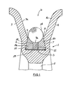
- Figure i of the accompanying drawings is a cross-section through the rim section of a sheave wheel according to the invention but is not drawn to scale.
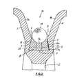
- Figure 2 of the accompanying drawings is a view similar to Figure I but illustrating a second preferred form of the invention.
- a sheave wheel is shown to have a rim i connected via spokes (one of which is shown at 2] to a hub [not shown].
- the rim I is provided with a circumferential groove ia which is bordered by a pair of flanges 3 and 4 and a transverse base 5 at the inner extremity of the groove.
- the outer segments of the flanges 3 and 4 having facing wall surfaces 3 a and 4 a which diverge from one another in the outward direction and which define between them a guide zone of the groove.
- the inner segments of the flanges have facing wall sections 6 and 7 which converge towards one another which collectively define a seat zone in the groove with the base 5.
- a wearing insert arrangement 8 is provided in the seat zone of the groove.
- the wearing insert comprises a pair of insert elements 8a and 8b which in operative alignment and registration collectively define an elongated block of truncated triangular or trapezoidal cross-sectional configuration.
- the insert elements 8a and 8b are substantially of identical shape and mate with one another along a split surface which extends substantially normally to the parallel surfaces 9 and Io of the block and at an angle of about 5° to the longitudinal axis of the composite block. The extremities of the split surface are indicated at II and 12.
- a resilient compression pad 13 is sandwiched between the lower surface I o of the composite block 8 and the base surface 5 of the slot.
- the compression pad 13 may be of any durable compressible material such as for example, TEFLON or HYTREL.
- a wearing insert arrangement 8 is provided in the seat zone of the groove.
- the wearing insert comprises a pair of insert elements 8a and 8b which in operative alignment and registration collectively define an elongated block of truncated triangular or trapezoidal cross-sectional configuration.
- the insert elements 8a and 8b are substantially of identical shape and mate with one another along a split surface which extends substantially normally to the parallel surfaces 9 and Io of the block and at an angle of about 5° to the longitudinal axis of the composite block. The extremities of the split surface are indicated at II and I2.
- a resilient compression pad 13 is sandwiched between the lower surface 10 of the composite block 8 and the base surface 5 of the slot.
- the compression pad 13 may be of any durable compressible material such as for example, TEFLON or HYTREL.
- the compression pad 13 is located in the slot and the two insert elements are located in off-set relationship relative to one another in the slot.
- the two elements 8a and 8b are then moved into registration with one another thereby firmly wedging the elements in the slot and compressing the compression pad 13 between the base 5 and the lower surface 10 of the insert elements.
- the insert elements may have a height of 70mm and the pad may be a HYTREL sheet of 12 . 5 mm thickness.
- the pad is compressed to a final thickness in the slot of between about 9.4 mm and II.2 mm.
- HYTREL and TEFLON are both trade marks for a polymeric material produced and marketed by E.I. du Pont de Nemours & Co. Inc.
- This arrangement is considered to have particular advantages over known arrangements and even over the arrangement shown in Figure 1 .
- One such advantage is that a thinner compression pad [I3a] may be used and using HYTREL to produce the compression pad its thickness may be between about 3 - 4 mm.
- Another advantage is that the insert element 8b and pad I3a may be located in place in the groove as shown and the insert clement 8a may then be driven home while it slides on metal surfaces on all three of its contact surfaces. Hence no sliding of metal over polymeric material is required and it will be appreciated that this feature greatly improves the tight seating of the inserts in the groove.
- the wearing surface 9 may be grooved as shown at 9 a to provide a seat for a cable or rope indicated at 14 .
Landscapes
- Engineering & Computer Science (AREA)
- General Engineering & Computer Science (AREA)
- Mechanical Engineering (AREA)
- Pulleys (AREA)
Applications Claiming Priority (2)
| Application Number | Priority Date | Filing Date | Title |
|---|---|---|---|
| ZA849880 | 1984-12-19 | ||
| ZA849880 | 1984-12-19 |
Publications (1)
| Publication Number | Publication Date |
|---|---|
| EP0185531A1 true EP0185531A1 (de) | 1986-06-25 |
Family
ID=25577658
Family Applications (1)
| Application Number | Title | Priority Date | Filing Date |
|---|---|---|---|
| EP85309124A Withdrawn EP0185531A1 (de) | 1984-12-19 | 1985-12-16 | Seilscheibe |
Country Status (3)
| Country | Link |
|---|---|
| EP (1) | EP0185531A1 (de) |
| AU (1) | AU5131085A (de) |
| ZW (1) | ZW23085A1 (de) |
Cited By (6)
| Publication number | Priority date | Publication date | Assignee | Title |
|---|---|---|---|---|
| DE19816327A1 (de) * | 1998-04-11 | 1999-10-14 | Wilhelm Kaechele Gmbh Elastome | Seilrolle |
| US8020669B2 (en) | 2000-12-08 | 2011-09-20 | Kone Corporation | Elevator and traction sheave of an elevator |
| CN103195911A (zh) * | 2013-04-19 | 2013-07-10 | 苏州铉动三维空间科技有限公司 | 一种导向轮 |
| US9212029B2 (en) * | 2010-03-11 | 2015-12-15 | Kone Corporation | Traction sheave elevator |
| EP3770100A1 (de) * | 2019-07-22 | 2021-01-27 | Otis Elevator Company | Aufzugsseilrollenauskleidung |
| US12188202B2 (en) | 2021-08-23 | 2025-01-07 | Caterpillar Global Mining Llc | Walking system with replaceable wear surfaces |
Citations (9)
| Publication number | Priority date | Publication date | Assignee | Title |
|---|---|---|---|---|
| DE505235C (de) * | 1930-08-16 | Pohlig Akt Ges J | Seiltreibscheibe | |
| DE809616C (de) * | 1948-10-06 | 1951-07-30 | Walter Oxe | Treib- und Seilscheibenfutter mit trapez- oder schwalbenschwanz-foermigem Querschnitt |
| DE810216C (de) * | 1948-10-06 | 1951-08-06 | Walter Oxe | Treib- und Seilscheibenfutter aus Metall, insbesondere Leichtmetall |
| DE838383C (de) * | 1949-09-10 | 1952-05-12 | Becorit Ges Wilhelm Beckmann & | Treib- oder Seilscheibe |
| DE934318C (de) * | 1948-10-06 | 1955-10-20 | Walter Oxe | Treib- und Seilscheibenfutter aus Metall, insbesondere Leichtmetall |
| DE957267C (de) * | 1950-04-27 | 1957-01-31 | Walter Oxe | Treib- und Seilscheibe |
| DE968615C (de) * | 1952-11-09 | 1958-03-13 | Walter Oxe | Treib- und Seilscheibe |
| DE1077009B (de) * | 1956-06-13 | 1960-03-03 | Becorit Ges Wilhelm Beckmann & | Futter fuer mit Drahtseilen zusammenarbeitende Seilscheiben, insbesondere Treibscheiben |
| DE1179055B (de) * | 1959-08-26 | 1964-10-01 | Walter Oxe | Treib- und Seilscheibenfutter aus im spitzen Winkel zur Umfangsrichtung geteilten Futter-kloetzen aus Leichtmetall mit Einlagen aus nachgiebigerem Material |
-
1985
- 1985-12-12 ZW ZW230/85A patent/ZW23085A1/xx unknown
- 1985-12-13 AU AU51310/85A patent/AU5131085A/en not_active Abandoned
- 1985-12-16 EP EP85309124A patent/EP0185531A1/de not_active Withdrawn
Patent Citations (9)
| Publication number | Priority date | Publication date | Assignee | Title |
|---|---|---|---|---|
| DE505235C (de) * | 1930-08-16 | Pohlig Akt Ges J | Seiltreibscheibe | |
| DE809616C (de) * | 1948-10-06 | 1951-07-30 | Walter Oxe | Treib- und Seilscheibenfutter mit trapez- oder schwalbenschwanz-foermigem Querschnitt |
| DE810216C (de) * | 1948-10-06 | 1951-08-06 | Walter Oxe | Treib- und Seilscheibenfutter aus Metall, insbesondere Leichtmetall |
| DE934318C (de) * | 1948-10-06 | 1955-10-20 | Walter Oxe | Treib- und Seilscheibenfutter aus Metall, insbesondere Leichtmetall |
| DE838383C (de) * | 1949-09-10 | 1952-05-12 | Becorit Ges Wilhelm Beckmann & | Treib- oder Seilscheibe |
| DE957267C (de) * | 1950-04-27 | 1957-01-31 | Walter Oxe | Treib- und Seilscheibe |
| DE968615C (de) * | 1952-11-09 | 1958-03-13 | Walter Oxe | Treib- und Seilscheibe |
| DE1077009B (de) * | 1956-06-13 | 1960-03-03 | Becorit Ges Wilhelm Beckmann & | Futter fuer mit Drahtseilen zusammenarbeitende Seilscheiben, insbesondere Treibscheiben |
| DE1179055B (de) * | 1959-08-26 | 1964-10-01 | Walter Oxe | Treib- und Seilscheibenfutter aus im spitzen Winkel zur Umfangsrichtung geteilten Futter-kloetzen aus Leichtmetall mit Einlagen aus nachgiebigerem Material |
Cited By (14)
| Publication number | Priority date | Publication date | Assignee | Title |
|---|---|---|---|---|
| DE19816327A1 (de) * | 1998-04-11 | 1999-10-14 | Wilhelm Kaechele Gmbh Elastome | Seilrolle |
| WO1999053223A1 (de) | 1998-04-11 | 1999-10-21 | Wilhelm Kächele GmbH Elastomertechnik | Seilrolle |
| DE19816327C2 (de) * | 1998-04-11 | 2002-06-13 | Wilhelm Kaechele Gmbh Elastome | Seilrolle |
| CN1109831C (zh) * | 1998-04-11 | 2003-05-28 | 威廉·卡彻勒合成橡胶技术股份有限公司 | 绳轮 |
| US6881166B1 (en) | 1998-04-11 | 2005-04-19 | Wilhelm Kaechele Gmbh Elastomertechnik | Pulley |
| US8069955B2 (en) * | 2000-12-08 | 2011-12-06 | Kone Corporation | Elevator and traction sheave of an elevator |
| US8020669B2 (en) | 2000-12-08 | 2011-09-20 | Kone Corporation | Elevator and traction sheave of an elevator |
| US9212029B2 (en) * | 2010-03-11 | 2015-12-15 | Kone Corporation | Traction sheave elevator |
| CN103195911A (zh) * | 2013-04-19 | 2013-07-10 | 苏州铉动三维空间科技有限公司 | 一种导向轮 |
| CN103195911B (zh) * | 2013-04-19 | 2016-04-20 | 丽水学院 | 一种导向轮 |
| EP3770100A1 (de) * | 2019-07-22 | 2021-01-27 | Otis Elevator Company | Aufzugsseilrollenauskleidung |
| CN112279049A (zh) * | 2019-07-22 | 2021-01-29 | 奥的斯电梯公司 | 电梯滑轮衬套 |
| US11117787B2 (en) | 2019-07-22 | 2021-09-14 | Otis Elevator Company | Elevator sheave liner |
| US12188202B2 (en) | 2021-08-23 | 2025-01-07 | Caterpillar Global Mining Llc | Walking system with replaceable wear surfaces |
Also Published As
| Publication number | Publication date |
|---|---|
| ZW23085A1 (en) | 1986-03-19 |
| AU5131085A (en) | 1986-06-26 |
Similar Documents
| Publication | Publication Date | Title |
|---|---|---|
| AU622183B2 (en) | Ring valve | |
| US5066147A (en) | Means for mounting a bearing ring | |
| US4130325A (en) | Thrust plate for the bearing pins of a trunnion in a universal joint | |
| US20080283720A1 (en) | Plate for a compressible elastomeric spring | |
| DE3027133C2 (de) | Gleitringdichtung | |
| EP0886078A3 (de) | Reibungsdämpfer mit einem Elastomerfederlement | |
| JP2002511555A (ja) | ロープ車 | |
| EP0185531A1 (de) | Seilscheibe | |
| DE4028951A1 (de) | Scheibenbremsvorrichtung | |
| US6635000B2 (en) | Roller for a running-gear mechanism or for a roller battery | |
| KR100563332B1 (ko) | 구동 벨트와 상기 구동 벨트의 요소 및 구동 벨트가 사용되는구조물. | |
| DE102004045327A1 (de) | Bremsscheibenanordung für Fahrzeugräder | |
| DE2624001C2 (de) | Zweiteiliges, in einer senkrecht zur Drehachse der Pumpenwelle liegenden Ebene geteiltes Gehäuse für eine mit hohem Druck betriebene Zentrifugalpumpe | |
| EP0692647A2 (de) | Lagereinheit | |
| US4700443A (en) | Method for the assembly of an inner race for a roller bearing and an annular cage whose openings contain rolling elements | |
| GB2102896A (en) | Rolling bearing arrangement | |
| US5372430A (en) | Bearing assembly | |
| US4629340A (en) | Roller bearing assembly | |
| RU2021900C1 (ru) | Колесо для железнодорожного транспортного средства | |
| GB1585501A (en) | Roller bearings | |
| DE2433928A1 (de) | Kombiniertes radial-axialgleitlager | |
| US4932509A (en) | Blade for liquid friction couplings | |
| US4542778A (en) | Tread for pneumatic vehicle tires | |
| DE19611677C2 (de) | Berührungsfreie Dichtung mit einem schwimmenden Ring | |
| US4573367A (en) | Closed rolling nut for transforming a rotary movement of a shaft into a thrust movement of the rolling nut |
Legal Events
| Date | Code | Title | Description |
|---|---|---|---|
| PUAI | Public reference made under article 153(3) epc to a published international application that has entered the european phase |
Free format text: ORIGINAL CODE: 0009012 |
|
| AK | Designated contracting states |
Kind code of ref document: A1 Designated state(s): DE GB |
|
| STAA | Information on the status of an ep patent application or granted ep patent |
Free format text: STATUS: THE APPLICATION IS DEEMED TO BE WITHDRAWN |
|
| 18D | Application deemed to be withdrawn |
Effective date: 19861229 |
|
| RIN1 | Information on inventor provided before grant (corrected) |
Inventor name: PILLINER, REGINALD SPENCER HYLTON |