EP0185582A1 - Interferometrischer Fühler mit optischer Faser - Google Patents
Interferometrischer Fühler mit optischer Faser Download PDFInfo
- Publication number
- EP0185582A1 EP0185582A1 EP85402374A EP85402374A EP0185582A1 EP 0185582 A1 EP0185582 A1 EP 0185582A1 EP 85402374 A EP85402374 A EP 85402374A EP 85402374 A EP85402374 A EP 85402374A EP 0185582 A1 EP0185582 A1 EP 0185582A1
- Authority
- EP
- European Patent Office
- Prior art keywords
- coupler
- wave
- arm
- optical
- laser source
- Prior art date
- Legal status (The legal status is an assumption and is not a legal conclusion. Google has not performed a legal analysis and makes no representation as to the accuracy of the status listed.)
- Granted
Links
- 230000003287 optical effect Effects 0.000 title claims abstract description 8
- 239000000835 fiber Substances 0.000 claims description 21
- 239000013307 optical fiber Substances 0.000 claims description 11
- 238000005259 measurement Methods 0.000 claims description 9
- 238000005260 corrosion Methods 0.000 description 2
- 230000007797 corrosion Effects 0.000 description 2
- 230000010365 information processing Effects 0.000 description 2
- 230000005855 radiation Effects 0.000 description 2
- 230000035945 sensitivity Effects 0.000 description 2
- 238000010009 beating Methods 0.000 description 1
- 238000000151 deposition Methods 0.000 description 1
- 238000001514 detection method Methods 0.000 description 1
- 238000010586 diagram Methods 0.000 description 1
- 238000006073 displacement reaction Methods 0.000 description 1
- 238000010292 electrical insulation Methods 0.000 description 1
- 230000005672 electromagnetic field Effects 0.000 description 1
- 239000011521 glass Substances 0.000 description 1
- 238000005305 interferometry Methods 0.000 description 1
- 238000002955 isolation Methods 0.000 description 1
- 238000000034 method Methods 0.000 description 1
- 244000045947 parasite Species 0.000 description 1
- 230000010287 polarization Effects 0.000 description 1
- 238000004611 spectroscopical analysis Methods 0.000 description 1
Images
Classifications
-
- G—PHYSICS
- G01—MEASURING; TESTING
- G01D—MEASURING NOT SPECIALLY ADAPTED FOR A SPECIFIC VARIABLE; ARRANGEMENTS FOR MEASURING TWO OR MORE VARIABLES NOT COVERED IN A SINGLE OTHER SUBCLASS; TARIFF METERING APPARATUS; MEASURING OR TESTING NOT OTHERWISE PROVIDED FOR
- G01D5/00—Mechanical means for transferring the output of a sensing member; Means for converting the output of a sensing member to another variable where the form or nature of the sensing member does not constrain the means for converting; Transducers not specially adapted for a specific variable
- G01D5/26—Mechanical means for transferring the output of a sensing member; Means for converting the output of a sensing member to another variable where the form or nature of the sensing member does not constrain the means for converting; Transducers not specially adapted for a specific variable characterised by optical transfer means, i.e. using infrared, visible, or ultraviolet light
- G01D5/268—Mechanical means for transferring the output of a sensing member; Means for converting the output of a sensing member to another variable where the form or nature of the sensing member does not constrain the means for converting; Transducers not specially adapted for a specific variable characterised by optical transfer means, i.e. using infrared, visible, or ultraviolet light using optical fibres
-
- G—PHYSICS
- G01—MEASURING; TESTING
- G01J—MEASUREMENT OF INTENSITY, VELOCITY, SPECTRAL CONTENT, POLARISATION, PHASE OR PULSE CHARACTERISTICS OF INFRARED, VISIBLE OR ULTRAVIOLET LIGHT; COLORIMETRY; RADIATION PYROMETRY
- G01J9/00—Measuring optical phase difference; Determining degree of coherence; Measuring optical wavelength
- G01J9/02—Measuring optical phase difference; Determining degree of coherence; Measuring optical wavelength by interferometric methods
- G01J2009/0226—Fibres
Definitions
- the present invention relates to an interferometric fiber optic sensor.
- Fiber optic interferometric sensors have already been described, and in particular sensors using a Mach-Zehnder interferometer (GB Hocker Appl. Opt., 18, 1445, 1979; GL Clark et al., SPIE 92 Interferometry 1979; T. Musha and coll., Appl. Opt., 21, 694, 1982).
- a Mach-Zehnder interferometer GHocker Appl. Opt., 18, 1445, 1979; GL Clark et al., SPIE 92 Interferometry 1979; T. Musha and coll., Appl. Opt., 21, 694, 1982.
- the measuring arm is constituted
- the present invention aims to remedy this drawback by providing an interferometric fiber optic sensor whose measurement arm is movable.
- the present invention thus relates to an interferometric fiber optic sensor, of the type comprising a laser source, an interferometer whose arms are formed of optical fibers, one of these arms comprising a measurement cell, and a detector at the output.
- the interferometer characterized in that it comprises:
- optical isolator between the laser source and the first coupler to prevent the return of part of the reflected wave to the laser source.
- the optical isolator can be of the type described by P. doctrine in Opto 82 p.63 ESI publications.
- the laser source can be a gas laser or a continuous or pulsed laser diode.
- the couplers used can be constituted by glass slides, separator cubes, wollastons or fiber couplers of the polished or fused type.
- Polished type fiber couplers have been described by Hervé Lefrère in Contribution to optical fiber gyrometry of inertial class, State Thesis, University of Nice, 1982, and by Michel Digonnet and HJ Shaw in Wavelength multiplexing in single mode fiber couplers, Applied Optics / Vol.22 n ° 3 / l February, 83, and fused type couplers have been described by Jacques Bures, Suzanne Lacroix, Christian Veilleux and Jean Lapierre in Some particular of monomode fused fiber couplers Applied Optics / Vol.23 n ° 7 / l April 84.
- the measurement and reference arms are made with multimode type optical fibers (internal diameter of approximately 10 to 300 ⁇ m) or of single-mode type (internal diameter of approximately 3 to 6 ⁇ m).
- the movable measuring arm may include one or more point measurement cells on the optical fiber, which may consist of one or more parts of the optical fiber itself.
- the measurement arm can also be designed to provide integrated measurement along the optical fiber.
- the measurement can relate to all the parameters which influence the index of the optical fiber and its length, and in particular the temperature, the pressure, the displacements, the stresses, the electromagnetic field.
- the reflecting surface can be a separate mirror or be formed at the end of the fiber by depositing metallic layers or thin layers.
- the detector can be a PIN or avalanche photodiode, a photomultiplier tube or any other device giving sufficient sensitivity.
- the detected signal can be the intensity but also the polarization, the frequency or the phase.
- This signal can then be processed by an electronic information processing device.
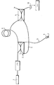
- the single figure is a diagram of a sensor according to the invention.
- a laser source 1 emits a wave which separates into two in a coupler 2, for example of the optical fiber type, operating as a separator.
- a fiber optic reference arm 3 transmits one of the parts of the separate wave to another coupler 4.
- the other part of the wave separated by the coupler 2 is transmitted to a movable measuring arm 5 comprising a measuring cell 6.
- the measuring arm 5 is terminated by a mirror 7 which returns a reflected wave to the coupler 2.
- a fiber optic deflection arm 8 returns part of the reflected wave from the coupler 2 to the coupler 4, while the other part of the reflected wave is returned to the laser source 1.
- An optical isolator 9 is interposed between the laser source 1 and the coupler 2 to prevent the return of the reflected wave to the laser source 1.
- the wave transmitted by the return arm 8 and the wave transmitted by the reference arm 3 interfere on a detector 10 coupled to an information processing device.
- cell 6 is a temperature-sensitive cell
- the sensor being sensitive to differences in optical path between the reference arm 3 and the measurement arm 5 and if the reference arm 3 is placed in an enclosure known temperature, it will be possible to determine the temperature difference between the temperature of the enclosure and the temperature of the place where the measuring cell 6 was placed.
Landscapes
- Physics & Mathematics (AREA)
- Spectroscopy & Molecular Physics (AREA)
- General Physics & Mathematics (AREA)
- Investigating Or Analysing Materials By Optical Means (AREA)
- Optical Transform (AREA)
- Instruments For Measurement Of Length By Optical Means (AREA)
- Gyroscopes (AREA)
- Light Guides In General And Applications Therefor (AREA)
- Measuring Fluid Pressure (AREA)
- Measuring Pulse, Heart Rate, Blood Pressure Or Blood Flow (AREA)
- Measurement Of Mechanical Vibrations Or Ultrasonic Waves (AREA)
Priority Applications (1)
| Application Number | Priority Date | Filing Date | Title |
|---|---|---|---|
| AT85402374T ATE42636T1 (de) | 1984-12-03 | 1985-12-02 | Interferometrischer fuehler mit optischer faser. |
Applications Claiming Priority (2)
| Application Number | Priority Date | Filing Date | Title |
|---|---|---|---|
| FR8418398A FR2574178B1 (fr) | 1984-12-03 | 1984-12-03 | Capteur interferometrique a fibre optique |
| FR8418398 | 1984-12-03 |
Publications (2)
| Publication Number | Publication Date |
|---|---|
| EP0185582A1 true EP0185582A1 (de) | 1986-06-25 |
| EP0185582B1 EP0185582B1 (de) | 1989-04-26 |
Family
ID=9310171
Family Applications (1)
| Application Number | Title | Priority Date | Filing Date |
|---|---|---|---|
| EP85402374A Expired EP0185582B1 (de) | 1984-12-03 | 1985-12-02 | Interferometrischer Fühler mit optischer Faser |
Country Status (4)
| Country | Link |
|---|---|
| EP (1) | EP0185582B1 (de) |
| AT (1) | ATE42636T1 (de) |
| DE (1) | DE3569823D1 (de) |
| FR (1) | FR2574178B1 (de) |
Cited By (2)
| Publication number | Priority date | Publication date | Assignee | Title |
|---|---|---|---|---|
| EP0398319A3 (de) * | 1989-05-19 | 1991-05-08 | Betriebsforschungsinstitut VDEh Institut für angewandte Forschung GmbH | Verfahren und Vorrichtung zur interferometrischen Detektion von Oberflächenverschiebungen bei Festkörpern |
| EP0450782A3 (en) * | 1990-03-19 | 1992-08-26 | Eli Lilly And Company | Fiberoptic interferometric sensor |
Citations (1)
| Publication number | Priority date | Publication date | Assignee | Title |
|---|---|---|---|---|
| GB2136956A (en) * | 1983-02-24 | 1984-09-26 | British Telecomm | Optical Fibre Interferometers |
-
1984
- 1984-12-03 FR FR8418398A patent/FR2574178B1/fr not_active Expired
-
1985
- 1985-12-02 DE DE8585402374T patent/DE3569823D1/de not_active Expired
- 1985-12-02 AT AT85402374T patent/ATE42636T1/de not_active IP Right Cessation
- 1985-12-02 EP EP85402374A patent/EP0185582B1/de not_active Expired
Patent Citations (1)
| Publication number | Priority date | Publication date | Assignee | Title |
|---|---|---|---|---|
| GB2136956A (en) * | 1983-02-24 | 1984-09-26 | British Telecomm | Optical Fibre Interferometers |
Non-Patent Citations (3)
| Title |
|---|
| APPLIED PHYSICS LETTERS, vol. 41, no. 3, 1er août 1982, pages 231-233, American Institute of Physics; J.E. BOWERS: "Fiber-optical sensor for surface acoustic waves" * |
| LASER FOCUS, vol. 18, no. 2, février 1982, pages 112-115, Newton, Mass., US; C.M. DAVIS: "An introduction to fiberoptic sensors" * |
| OPTICS COMMUNICATIONS, vol. 39, no. 1,2, 15 septembre 1981, pages 7-10, North-Holland Publishing Co., Amsterdam, NL; M. IMAI et al.: "High-sensitive all-fiber Michelson interferometer by use of differential output configuration" * |
Cited By (2)
| Publication number | Priority date | Publication date | Assignee | Title |
|---|---|---|---|---|
| EP0398319A3 (de) * | 1989-05-19 | 1991-05-08 | Betriebsforschungsinstitut VDEh Institut für angewandte Forschung GmbH | Verfahren und Vorrichtung zur interferometrischen Detektion von Oberflächenverschiebungen bei Festkörpern |
| EP0450782A3 (en) * | 1990-03-19 | 1992-08-26 | Eli Lilly And Company | Fiberoptic interferometric sensor |
Also Published As
| Publication number | Publication date |
|---|---|
| DE3569823D1 (en) | 1989-06-01 |
| EP0185582B1 (de) | 1989-04-26 |
| ATE42636T1 (de) | 1989-05-15 |
| FR2574178A1 (fr) | 1986-06-06 |
| FR2574178B1 (fr) | 1987-02-20 |
Similar Documents
| Publication | Publication Date | Title |
|---|---|---|
| US11150144B2 (en) | Sapphire sensor for measuring pressure and temperature with improved stress and temperature variation compensation | |
| US5345519A (en) | Temperature-compensated fiber optic external cavity strain sensors and an intensity-based fiber optic sensor system | |
| CN101253392B (zh) | 光纤温度和压力传感器和包括它们的系统 | |
| US9404771B2 (en) | Optical sensor | |
| FR2613477A1 (fr) | Capteur optique de deplacement et de pression | |
| EP0326475A1 (de) | Faseroptischer Mehrpunkt-Temperatursensor | |
| FR2542868A1 (fr) | Capteur a cavites de fabry-perot | |
| FR2613065A1 (fr) | Interferometre de michelson a fibres optiques et son application notamment a la mesure des temperatures | |
| CN106197492B (zh) | 基于光纤复合法珀腔结构的法珀腔长与折射率计算方法 | |
| US4804264A (en) | Arrangement for time-resolved optical backscatter measurement at optical waveguides | |
| EP0234309A2 (de) | Verfahren und Vorrichtung zur Fernmessung der Verteilung eines physisch-chemischen Parameters in einem Medium | |
| KR20170098518A (ko) | 광센서 | |
| EP0298091A1 (de) | Optische sensoren und optisches fasernetz für diese sensoren | |
| EP0399861A1 (de) | Lesevorrichtung für polarimetrische und interferometrische Sensoren | |
| EP0493169B1 (de) | Analysevorrichtung für interferometrische Mikroverschiebungssensoren | |
| EP0185582B1 (de) | Interferometrischer Fühler mit optischer Faser | |
| EP1019688A1 (de) | Vorrichtung zur messung der wellenlänge eines lichtbündels | |
| JPS6230921A (ja) | 光学式センサ | |
| RU2057285C1 (ru) | Волоконно-оптический датчик перемещений | |
| JPS5714729A (en) | Temperature measuring device | |
| FR2765964A1 (fr) | Dispositif optique de mesure de distance avec une grande precision | |
| FR2675900A1 (fr) | Capteur de vibrations a fibre optique et accelerometre utilisant un tel capteur. | |
| JPS6135492B2 (de) | ||
| FR2653254A1 (fr) | Dispositif pour effectuer la mesure d'une grandeur physique et la transmission a distance de la valeur relevee de cette grandeur. | |
| Wang et al. | Sapphire-optical-fiber-based interferometric sensors for high-temperature environmental applications |
Legal Events
| Date | Code | Title | Description |
|---|---|---|---|
| PUAI | Public reference made under article 153(3) epc to a published international application that has entered the european phase |
Free format text: ORIGINAL CODE: 0009012 |
|
| AK | Designated contracting states |
Kind code of ref document: A1 Designated state(s): AT BE CH DE GB IT LI LU NL SE |
|
| 17P | Request for examination filed |
Effective date: 19861115 |
|
| 17Q | First examination report despatched |
Effective date: 19880506 |
|
| ITF | It: translation for a ep patent filed | ||
| GRAA | (expected) grant |
Free format text: ORIGINAL CODE: 0009210 |
|
| AK | Designated contracting states |
Kind code of ref document: B1 Designated state(s): AT BE CH DE GB IT LI LU NL SE |
|
| PG25 | Lapsed in a contracting state [announced via postgrant information from national office to epo] |
Ref country code: SE Effective date: 19890426 Ref country code: NL Effective date: 19890426 Ref country code: AT Effective date: 19890426 |
|
| REF | Corresponds to: |
Ref document number: 42636 Country of ref document: AT Date of ref document: 19890515 Kind code of ref document: T |
|
| REF | Corresponds to: |
Ref document number: 3569823 Country of ref document: DE Date of ref document: 19890601 |
|
| GBT | Gb: translation of ep patent filed (gb section 77(6)(a)/1977) | ||
| NLV1 | Nl: lapsed or annulled due to failure to fulfill the requirements of art. 29p and 29m of the patents act | ||
| PLBE | No opposition filed within time limit |
Free format text: ORIGINAL CODE: 0009261 |
|
| STAA | Information on the status of an ep patent application or granted ep patent |
Free format text: STATUS: NO OPPOSITION FILED WITHIN TIME LIMIT |
|
| 26N | No opposition filed | ||
| ITTA | It: last paid annual fee | ||
| EPTA | Lu: last paid annual fee | ||
| REG | Reference to a national code |
Ref country code: GB Ref legal event code: IF02 |
|
| PGFP | Annual fee paid to national office [announced via postgrant information from national office to epo] |
Ref country code: CH Payment date: 20021115 Year of fee payment: 18 |
|
| PGFP | Annual fee paid to national office [announced via postgrant information from national office to epo] |
Ref country code: GB Payment date: 20021125 Year of fee payment: 18 |
|
| PGFP | Annual fee paid to national office [announced via postgrant information from national office to epo] |
Ref country code: DE Payment date: 20021211 Year of fee payment: 18 |
|
| PGFP | Annual fee paid to national office [announced via postgrant information from national office to epo] |
Ref country code: LU Payment date: 20021216 Year of fee payment: 18 |
|
| PGFP | Annual fee paid to national office [announced via postgrant information from national office to epo] |
Ref country code: BE Payment date: 20030102 Year of fee payment: 18 |
|
| PG25 | Lapsed in a contracting state [announced via postgrant information from national office to epo] |
Ref country code: LU Free format text: LAPSE BECAUSE OF NON-PAYMENT OF DUE FEES Effective date: 20031202 Ref country code: GB Free format text: LAPSE BECAUSE OF NON-PAYMENT OF DUE FEES Effective date: 20031202 |
|
| PG25 | Lapsed in a contracting state [announced via postgrant information from national office to epo] |
Ref country code: LI Free format text: LAPSE BECAUSE OF NON-PAYMENT OF DUE FEES Effective date: 20031231 Ref country code: CH Free format text: LAPSE BECAUSE OF NON-PAYMENT OF DUE FEES Effective date: 20031231 Ref country code: BE Free format text: LAPSE BECAUSE OF NON-PAYMENT OF DUE FEES Effective date: 20031231 |
|
| BERE | Be: lapsed |
Owner name: *ELECTRICITE DE FRANCE SERVICE NATIONAL Effective date: 20031231 |
|
| PG25 | Lapsed in a contracting state [announced via postgrant information from national office to epo] |
Ref country code: DE Free format text: LAPSE BECAUSE OF NON-PAYMENT OF DUE FEES Effective date: 20040701 |
|
| GBPC | Gb: european patent ceased through non-payment of renewal fee |
Effective date: 20031202 |
|
| REG | Reference to a national code |
Ref country code: CH Ref legal event code: PL |