EP0185636A1 - Loser Rahmen für Gattersägen - Google Patents
Loser Rahmen für Gattersägen Download PDFInfo
- Publication number
- EP0185636A1 EP0185636A1 EP19850850391 EP85850391A EP0185636A1 EP 0185636 A1 EP0185636 A1 EP 0185636A1 EP 19850850391 EP19850850391 EP 19850850391 EP 85850391 A EP85850391 A EP 85850391A EP 0185636 A1 EP0185636 A1 EP 0185636A1
- Authority
- EP
- European Patent Office
- Prior art keywords
- saw
- recess
- saw blade
- frame
- blocks
- Prior art date
- Legal status (The legal status is an assumption and is not a legal conclusion. Google has not performed a legal analysis and makes no representation as to the accuracy of the status listed.)
- Ceased
Links
Images
Classifications
-
- B—PERFORMING OPERATIONS; TRANSPORTING
- B27—WORKING OR PRESERVING WOOD OR SIMILAR MATERIAL; NAILING OR STAPLING MACHINES IN GENERAL
- B27B—SAWS FOR WOOD OR SIMILAR MATERIAL; COMPONENTS OR ACCESSORIES THEREFOR
- B27B3/00—Gang saw mills; Other sawing machines with reciprocating saw blades, specially designed for length sawing of trunks
- B27B3/28—Components
- B27B3/30—Blade attachments, e.g. saw buckles; Stretching devices
Definitions
- This invention relates to a loose frame for gang saws, comprising saw blade holders which are mounted in the frame opening and movable towards and away from one another by clamping means on the frame end members and in which opposite saw blade ends are attachable for tensioning the saw blades in the frame opening parallel to the frame side members.
- Exchanging saw blades in a gang saw is difficult and time-consuming work because the saw blades after mounting must be exactly and accurately oriented relative to one another and the frame.
- the saw blades are mounted in a frame which, in larger gang saws, is held in the sash during the so-called setting-up but which, in smaller saws, can be removed from the sash and set up in advance, in which case the down-time naturally will be much shorter than in the first-mentioned case.
- the setting-up is still a difficult operation because of the many loose components which also make for poor precision and extensive adjustments.
- these components are expensive, and after mounting in the frame it is frequently difficult to obtain the highest blade tension exactly where one wants it, i.e.. in the leading edge of the blades which is the edge carrying the saw teeth.
- the present invention aims at providing a novel loose frame of the above-mentioned type by which the setting-up is greatly facilitated so that it can be carried out quickly and normally without subsequent adjustments.
- at least one saw blade holder has a recess which is open towards the frame opening and ends at a distance from the saw blade holder ends to form end walls; that setting-up blocks of a shape corresponding to the cross-section of the saw blade holder recess and of predetermined thickness are fixable in the recess, with the saw blades therebetween; that fixing means are provided in the end walls of the saw blade holder for fixing the saw blades and the blocks within the recess; and that the saw blades and the blocks are provided with at least one reces in one of their edges, said recesses being identical and located, after the saw blades and the blocks have been fixed in the recess of the saw blade holder, opposite one another in the longitudinal direc- ion of said recess, such that a rib attachable to said holder can be pressed down there
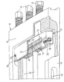
- the drawing shows the upper part of a loose frame generally designated 10 and intended to be mounted in conventional manner in the sash of a gang saw.
- the lower part of the frame 10 is not shown because it is normally of the same design as the upper part illustrated in the drawing.
- the frame 10 comprises side members 11 and end members 12 which are integral with said side members and together define an rectangular frame opening.
- the side members 11 of the frame 10 may be provided with recesses adapted to reduce the weight of the frame.
- a saw blade holder 14 is provided by means of which saw blades 16 can be clamped therein parallel to said side members 11. At least one saw blade holder 14 is engaged by three clamping screws 15 mounted in threaded bores in the end member 12 of the frame 10.
- the saw blade holder 14 illustrated in the drawing has a rectangular recess 21 which is open towards the frame opening and along the left-hand side of the holder 14, as seen in the drawing, i.e. the recess 21 is defined by two walls perpendicular to one another.
- the recess 21 terminates at a distance from the ends of the saw blade holder 14 to form relatively thick end walls 22.
- Rectangular setting-up blocks 17 of predetermined thickness are adapted to be mounted in the recess 21. After the blocks 17 have been disposed in the recess 21, one edge surface of said blocks is on a level with the left-hand lateral plane of the holder 14, while the edge portion of the blocks 17 facing the frame opening slightly protrudes from the surface of the holder 14 facing the frame opening.
- the saw blades 16 are mounted between the blocks 17, as shown in the drawing, whereby the saw blades can be easily mounted in desired spaced apart positions in the transverse direction.
- a package consisting of setting-up blocks 17 and saw blade ends may thus be mounted in the recess 21 in the manner illustrated in the drawing and fixably positioned by means of a screw 18 extending through the end wall 22.
- the saw blades 16 are provided at a predetermined distance from their ends with a rectangular recess 23, and the setting-up blocks 17 have, at the same distance from their edge side facing away from the frame opening, a recess 26 which is identical with the saw blade recess 23.
- the saw blades 16 and the blocks 17 are readily locked by means of these recesses 23, 26 and a ca, pr rib 24 on the underside of a plate 19.
- the cam or rib 24 has exactly the same cross-sectional shape as the recesses 23, 26 and can be pressed down into these recesses with a suitable fit
- the plate 19 has approximately the same extent as the side of the holder 14 which is turned to the left in the drawing, and suitable guides 25 may be provided.
- the plate 19 is locked in position by means of the cam or rib 24 extending into the recesses 23, 26 by means of bolts 20 that can be screwed into threaded bores in the end walls of the holder 14.
- the inner surface of the side members 11 and one end surface of the holder 14 may be finished such that the saw blades 16 will always extend exactly parallel to the frame members 1 1 . In this manner, subsequent adjustments of the clamped blade package are avoided.
- the bolts 15 are first loosened to relieve the tension of the blades 16. Then the bolts 20 are removed, whereby the plate 19 can be taken out After the screw 18 has been loosened, the entire blade package can be removed in one motion, and new saw blades 16 are easily inserted between the setting-up Mocks 17. After that, fixing and locking is effected in the manner described above.
- the arrangement according to the invention brings considerable advantages, and an exchange of saw blades can be effected safely and quickly.
- the provision of the recess 23 in the saw blade edge carrying the saw blade teeth automatically brings the advantage that the highest saw blade tension is obtained at the desired position, i.e. the leading edge of the blades.
- the drawing shows but one recess in the setting-up blocks, and saw blades with several recesses may be provided, if this is deemed necessary.
- the recesses in the blocks and the saw blades need not have the rectangular shape illustrated but may have a slight downward taper, or some other suitable shape.
Landscapes
- Life Sciences & Earth Sciences (AREA)
- Engineering & Computer Science (AREA)
- Mechanical Engineering (AREA)
- Wood Science & Technology (AREA)
- Forests & Forestry (AREA)
- Sawing (AREA)
Applications Claiming Priority (2)
| Application Number | Priority Date | Filing Date | Title |
|---|---|---|---|
| SE8406474 | 1984-12-19 | ||
| SE8406474A SE446608B (sv) | 1984-12-19 | 1984-12-19 | Losram till ramsag |
Publications (1)
| Publication Number | Publication Date |
|---|---|
| EP0185636A1 true EP0185636A1 (de) | 1986-06-25 |
Family
ID=20358235
Family Applications (1)
| Application Number | Title | Priority Date | Filing Date |
|---|---|---|---|
| EP19850850391 Ceased EP0185636A1 (de) | 1984-12-19 | 1985-12-04 | Loser Rahmen für Gattersägen |
Country Status (2)
| Country | Link |
|---|---|
| EP (1) | EP0185636A1 (de) |
| SE (1) | SE446608B (de) |
Citations (3)
| Publication number | Priority date | Publication date | Assignee | Title |
|---|---|---|---|---|
| AT102151B (de) * | 1924-11-29 | 1925-12-28 | Mathias Thuer | Beilageblatt zum Einspannen der Sägeblätter auf beliebige Brettstärken bei Vollgattern mit zwei Registerstangen. |
| AT187679B (de) * | 1954-05-26 | 1956-11-10 | Busatis Geb Gmbh | Vorrichtung zum Einspannen von Gattersägeblättern |
| AT314804B (de) * | 1971-06-24 | 1974-04-25 | Jansen Fa R | Hydraulische Druckregister für Gatterrahmen von Gattersägen |
-
1984
- 1984-12-19 SE SE8406474A patent/SE446608B/sv not_active IP Right Cessation
-
1985
- 1985-12-04 EP EP19850850391 patent/EP0185636A1/de not_active Ceased
Patent Citations (3)
| Publication number | Priority date | Publication date | Assignee | Title |
|---|---|---|---|---|
| AT102151B (de) * | 1924-11-29 | 1925-12-28 | Mathias Thuer | Beilageblatt zum Einspannen der Sägeblätter auf beliebige Brettstärken bei Vollgattern mit zwei Registerstangen. |
| AT187679B (de) * | 1954-05-26 | 1956-11-10 | Busatis Geb Gmbh | Vorrichtung zum Einspannen von Gattersägeblättern |
| AT314804B (de) * | 1971-06-24 | 1974-04-25 | Jansen Fa R | Hydraulische Druckregister für Gatterrahmen von Gattersägen |
Also Published As
| Publication number | Publication date |
|---|---|
| SE8406474L (sv) | 1986-06-20 |
| SE446608B (sv) | 1986-09-29 |
| SE8406474D0 (sv) | 1984-12-19 |
Similar Documents
| Publication | Publication Date | Title |
|---|---|---|
| US5159864A (en) | Insert for a table saw | |
| US6543323B2 (en) | Vice device in compound miter saw | |
| US4836494A (en) | Device for mounting a rail or the like on a surface | |
| US4443136A (en) | Machine cutting tool | |
| US4677920A (en) | Adjustable side extensions for work table | |
| EP2969421B1 (de) | Rolltischanordnung für eine sägemaschine | |
| US5330297A (en) | Boring tool | |
| US4918971A (en) | Bending tool | |
| US5163490A (en) | Knife clamp for wood planing heads | |
| JP3662044B2 (ja) | リーマ | |
| US20090261217A1 (en) | Insert Plate Leveling | |
| US4819703A (en) | Blade mount for planar head | |
| EP1366844A1 (de) | Vorrichtung zum Abtrennen von mehrwandigen Werkstücken | |
| US3777793A (en) | Knife holder in log slabbing chipper | |
| WO1991012939A1 (en) | Woodworking worktable assembly having an extruded t-slot | |
| US5501256A (en) | Chipper knife | |
| EP1063041A2 (de) | Werkzeugsystem für spannenden Metallbearbeitung von plattenförmigen Werkstücken | |
| US4095632A (en) | Straight edge cutting guide for router and circular saw | |
| US4137000A (en) | Cutting tool | |
| US5048580A (en) | Workpiece guide for portable power router | |
| US6425308B2 (en) | Toolholder with a removable head | |
| US4317400A (en) | Saw guide clamping assembly | |
| US2833026A (en) | All purpose tool element holder | |
| US5007774A (en) | Cutting or drawing tool | |
| US3667514A (en) | Guiding circular saws |
Legal Events
| Date | Code | Title | Description |
|---|---|---|---|
| PUAI | Public reference made under article 153(3) epc to a published international application that has entered the european phase |
Free format text: ORIGINAL CODE: 0009012 |
|
| AK | Designated contracting states |
Kind code of ref document: A1 Designated state(s): AT BE CH DE FR GB IT LI LU NL SE |
|
| RAP1 | Party data changed (applicant data changed or rights of an application transferred) |
Owner name: ASTRAND, CARL VIKTOR |
|
| 17P | Request for examination filed |
Effective date: 19861006 |
|
| 17Q | First examination report despatched |
Effective date: 19871020 |
|
| STAA | Information on the status of an ep patent application or granted ep patent |
Free format text: STATUS: THE APPLICATION HAS BEEN REFUSED |
|
| 18R | Application refused |
Effective date: 19880411 |