EP0185744B1 - Verfahren und werkzeug zum erweitern eines schornsteinkanals - Google Patents
Verfahren und werkzeug zum erweitern eines schornsteinkanals Download PDFInfo
- Publication number
- EP0185744B1 EP0185744B1 EP85903230A EP85903230A EP0185744B1 EP 0185744 B1 EP0185744 B1 EP 0185744B1 EP 85903230 A EP85903230 A EP 85903230A EP 85903230 A EP85903230 A EP 85903230A EP 0185744 B1 EP0185744 B1 EP 0185744B1
- Authority
- EP
- European Patent Office
- Prior art keywords
- chimney
- chains
- clear
- width
- tool
- Prior art date
- Legal status (The legal status is an assumption and is not a legal conclusion. Google has not performed a legal analysis and makes no representation as to the accuracy of the status listed.)
- Expired
Links
Images



Classifications
-
- F—MECHANICAL ENGINEERING; LIGHTING; HEATING; WEAPONS; BLASTING
- F23—COMBUSTION APPARATUS; COMBUSTION PROCESSES
- F23J—REMOVAL OR TREATMENT OF COMBUSTION PRODUCTS OR COMBUSTION RESIDUES; FLUES
- F23J3/00—Removing solid residues from passages or chambers beyond the fire, e.g. from flues by soot blowers
- F23J3/02—Cleaning furnace tubes; Cleaning flues or chimneys
- F23J3/026—Cleaning furnace tubes; Cleaning flues or chimneys cleaning the chimneys
-
- B—PERFORMING OPERATIONS; TRANSPORTING
- B25—HAND TOOLS; PORTABLE POWER-DRIVEN TOOLS; MANIPULATORS
- B25D—PERCUSSIVE TOOLS
- B25D11/00—Portable percussive tools with electromotor or other motor drive
- B25D11/06—Means for driving the impulse member
- B25D11/066—Means for driving the impulse member using centrifugal or rotary impact elements
-
- B—PERFORMING OPERATIONS; TRANSPORTING
- B28—WORKING CEMENT, CLAY, OR STONE
- B28D—WORKING STONE OR STONE-LIKE MATERIALS
- B28D1/00—Working stone or stone-like materials, e.g. brick, concrete or glass, not provided for elsewhere; Machines, devices, tools therefor
- B28D1/18—Working stone or stone-like materials, e.g. brick, concrete or glass, not provided for elsewhere; Machines, devices, tools therefor by milling, e.g. channelling by means of milling tools
-
- B—PERFORMING OPERATIONS; TRANSPORTING
- B28—WORKING CEMENT, CLAY, OR STONE
- B28D—WORKING STONE OR STONE-LIKE MATERIALS
- B28D1/00—Working stone or stone-like materials, e.g. brick, concrete or glass, not provided for elsewhere; Machines, devices, tools therefor
- B28D1/18—Working stone or stone-like materials, e.g. brick, concrete or glass, not provided for elsewhere; Machines, devices, tools therefor by milling, e.g. channelling by means of milling tools
- B28D1/186—Tools therefor, e.g. having exchangeable cutter bits
-
- E—FIXED CONSTRUCTIONS
- E04—BUILDING
- E04F—FINISHING WORK ON BUILDINGS, e.g. STAIRS, FLOORS
- E04F21/00—Implements for finishing work on buildings
- E04F21/02—Implements for finishing work on buildings for applying plasticised masses to surfaces, e.g. plastering walls
- E04F21/06—Implements for applying plaster, insulating material, or the like
- E04F21/14—Implements for applying plaster, insulating material, or the like in shafts, e.g. chimneys
-
- E—FIXED CONSTRUCTIONS
- E04—BUILDING
- E04G—SCAFFOLDING; FORMS; SHUTTERING; BUILDING IMPLEMENTS OR AIDS, OR THEIR USE; HANDLING BUILDING MATERIALS ON THE SITE; REPAIRING, BREAKING-UP OR OTHER WORK ON EXISTING BUILDINGS
- E04G23/00—Working measures on existing buildings
- E04G23/008—Working measures on existing vertical ducts, e.g. chimneys, garbage chutes
-
- E—FIXED CONSTRUCTIONS
- E04—BUILDING
- E04G—SCAFFOLDING; FORMS; SHUTTERING; BUILDING IMPLEMENTS OR AIDS, OR THEIR USE; HANDLING BUILDING MATERIALS ON THE SITE; REPAIRING, BREAKING-UP OR OTHER WORK ON EXISTING BUILDINGS
- E04G23/00—Working measures on existing buildings
- E04G23/02—Repairing, e.g. filling cracks; Restoring; Altering; Enlarging
Definitions
- the invention relates to a method for increasing the width in the clear of a chimney by means of a rotary tool having radially yieldable means, and an apparatus for carrying out the method for increasing the width in the clear of a chimney by means of a rotary tool comprising a holder mounted at the free end of a rotatable shaft and having chains, consisting e.g. of simple, elongated, ring-shaped chain links, which are fixedly mounted on several levels at right angles to the rotatable shaft.
- FR-A-707,546 discloses a method for increasing the width in the clear of a chimney by means of rotary bodies, in which method the inside of the chimney is processed by strokes of high intensity from several bodies disposed on different levels.
- Said bodies are rigid plates each of which is pivotally mounted on a shaft which is provided on a holder in such a manner that the bodies can execute but a limited pivotal movement.
- This tool is capable of increasing the width in the clear of an existing chimney, provided it consists of suitable soft material, but because of the restricted pivotment of the bodies, this tool can only be used in chimneys where the width in the clear is merely reduced to an insignificant extent, for instance by deposits of shining soot. Therefore, this tool cannot be used for increasing the width in the clear of an existing chimney to such an extent that it will be possible to insert a lining in the widened chimney.
- the method of the invention should allow not only to remove existing soot deposits in the chimney but also to remove materials from the interior wall surface of the chimney to such an extent that a lining tube can be inserted in the chimney.
- this object is achieved by a method of the above-mentioned type, which is characterized in that use is made of a rotary tool having chains disposed on several immediately adjoining levels, that the rotary tool is lowered from the top of the chimney to the bottom thereof, that the tool guided by guide means is moved upwards through the chimney while increasing the width in the clear thereof to a greater value than that of the original width in the clear, that the material pulverized during the reaming operation is withdrawn at the bottom of the chimney, for instance by a vacuum cleaner, that a lining of an internal diameter corresponding to the original width in the clear is inserted in the widened width in the clear, the external diameter of the lining being slightly less than said greater value of the width in the clear of the chimney, and that a remaining void between the lining and the inner wall of the chimney is filled with a material, preferably a mass capable of producing an intimate bond between the inner wall of the chimney and the outer wall of the lining.
- the tool For starting the reaming of the chimney or the object concerned from the bottom, the tool is pulled up through the chimney. If, on the other hand, the tool should be inserted from the top of the chimney, it had been necessary to subject the flexible shaft to a pressure in the longitudinal direction thereof, whereby the shaft would easily be deflected with detrimetal consequences. Also, the reaming operation according to the invention is conveniently started in that the tool can be guided in the original width in the clear of the chimney.
- the material removed by the reaming operation can drop freely through the widened width in the clear of the chimney to the bottom thereof, whereas when engaging the tool from above, the material removed would have remained on the rim between the original width in the clear and the widened one and would embarrass the rotation of the tool.
- the rotary tool can easily be lowered in the chimney since owing to its radially yieldable means, it occupies such a radial dimension that it can be descended through the chimney.
- the material milled off from the interior of the chimney becomes completely pulverized if this material is brick or a conventional chimney lining material while, when being concrete from the chimney top slab, it will be broken into relatively small fragments. It is then possible to withdraw the pulverized material at the bottom of the chimney by means of a vacuum cleaner or like apparatus.
- the necessary lining can conveniently be inserted in the smoothly milled chimney, whereupon the remaining void between the outer side of the lining and the inner wall of the chimney is filled with a suitable material, preferably a mass capable of providing an intimate bond between the inner wall of the chimney and the lining.
- Reaming of a chimney with the subsequent insertion of a lining tube in the chimney can be carried out by the method and the apparatus according to the invention at a relatively low cost and without any additional expenses for roof covering, work required by carpenters or painters. This cost should be compared with the costs for rebuilding the chimney.
- the invention also relates to an apparatus for carrying out the method for increasing the width in the clear of a chimney by means of a rotary tool
- a rotary tool comprising a holder mounted at the free end of a rotatable shaft and having chains, consisting e.g. of simple, elongated, ring-shaped chain links, which are fixedly mounted on several levels at right angles to the rotatable shaft, said apparatus being characterized in that the chains are disposed on levels immediately adjoining each other, that the rotatable shaft is rotatably mounted immediately above said holder in a guiding unit having outer dimensions at right angles to the rotatable shaft which are but slightly less than the original width in the clear of the chimney, and that the tool comprises means for lowering and lifting the guiding unit, the shaft, the holder and the chains in the chimney.
- This tool is very simple and makes it possible in an appropriate manner to carry out the method of the invention, in that the apparatus according to the invention permits processing the inner side of a chimney or a chimney lining at a high intensity and by means of several chains as stated above.
- the use of chains on several levels, preferably eight, at right angles to the rotatable shaft ensures adequate processing of a suitably large zone in a chimney as the chains simultaneously support each other in a suitable manner. Also, there is achieved an apparatus which is not too heavy and which is easy to handle, and there is provided a better possibility of reaming or cleaning chimneys with openings that do not extend linearly, which is often the case especially in older houses, where the chimney pot is located on the roof ridge and the vertical part of the chimney is offset in relation thereto.
- chains consisting of a hard and heavy material, for instance hardened steel, the uttermost chain links optionally containing. diamond dust, and to form the chain links preferably with a thickness of 5-6 mm, so as to obtain elements that are suitably hard and have a sufficiently large mass to process the inner side of the chimney with the force of impact required.
- the means for lowering and lifting the guiding unit, the shaft, the holder and the chains comprise a rack which can be mounted on the top of the chimney and which has a pulley for guiding the flexible shaft, so as to achieve a simple way of operating the rotary tool.
- FIG. 1 schematically shows a tool according to the invention during the lowering into a chimney
- a guiding unit 3 is shown, which is advantageously an electric hand drill.
- the guiding unit 3 is connected with a flexible shaft 6 by means of an elastic coupling 7 which can be disconnected.
- the guiding unit can advantageously be located on the roof, as the flexible coupling 7 as well as the distance between the guiding unit 3 and the chimney 1 has the effect that during operation the guiding unit 3 will not be moving on the roof.
- the flexible shaft 6 is in the opposite end connected to a rotor head 4, on which are mounted a number of chains 5.
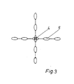
- a more detailed rotor head 4 is shown, on which are mounted four chains 5, same having an odd number of links, and same being firmly fixed through the central links. It is of course possible to use a different number of chains 5, just as these may be connected to the rotor head in various manners known per se, as long as they are firmly fixed.
- the chains 5 are advantageously made from iron or a similar strong and heavy material, for instance hardened steel, and preferably they have a gauge of metal of 5-6 mm.
- the uttermost links may, if desired, contain diamond dust, which is of particular importance if part of a concrete material is to be removed. When eight chains being located crossed above each other are used, a height of the "chain pile" of approximately 10 cm is typically obtained.
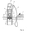
- Fig. 4 is shown the tool according to the invention for use by the method according to the invention for milling a chimney, in order that the width in the clear is increased.
- a guiding unit 15 through which the flexible shaft 6 has been conducted.
- the guiding unit is located immediately above the rotor head 4 and may have the form of a tube section, same at its ends being provided with two truncated cones, and with a hole through it.
- the diameter of the guiding unit is preferably somewhat smaller than the width in the clear in the chimney, the width of which is to be increased, said guiding unit for a chimney flue with a width in the clear of 15 cm having for instance a diameter of 14.5 cm. Adjusting the length of the chains 5 determines how much is to be milled off.
- an "Iso-kaern"-lining may be milled, removing both the inner tube and the Leca-casting while leaving the chimney itself, and using as driving unit 3 a more powerful engine than for the removal of soot. Then, in the usual manner a new lining can be inserted.
- the tool may also be used for the removal of the interior of an "Anki”-chimney or a "Kaminent”-chimney. By the removal the lining is pulverized and drops to the bottom in the chimney. So far it has not been possible selectively to remove a lining in a chimney, either after a fire or if an increase of.the width in the clear of the chimney is required out of consideration for another application than the original.
- a guiding unit in the form of an electric motor or a combustion engine e.g. an engine ranging up to 3.7 Kw (5 HP) would be suitable.
- a 1.5 kw (2 HP) electric motor may for instance be used.
- the rotor head When using the method and the tool for the removal of coatings such as soot, the rotor head is lowered into the chimney, whereupon the rotation is started.
- soot coatings it is possible to hold the tool with the hand, as the cleaning is rapidly done and the tool is light.
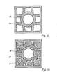
- Figs. 5, 7 and 9 show a sectional view along - the line a-a in Fig. 4 in three chimneys of a traditional brick-built construction, of tile concrete elements and of light concrete elements, respectively
- Fig. 6, 8 and 10 show a sectional view along the line b-b in Fig. 4 after "milling" of the chimneys shown in Figs. 5, 7 and 9, respectively, and insertion of a chimney lining, e.g. an "Iso-kaern"-chimney lining, and after casting around the lining with a mass, e.g. Leca-concrete.
- a chimney lining e.g. an "Iso-kaern"-chimney lining
- lining may also, if desired, be inserted a steel lining, and for the casting around the lining may also be used granulated rock wool, e.g. "Rockwool”-granulate mixed with water or a product called “Fibo", corresponding to "Leca”.
- Rockwool granulated rock wool
- the chimney shown in Fig. 5, built of bricks 17 with mortar joints 18 may according to the method be given a smaller width in the clear by inserting a chimney lining.
- the lining 19 shown in Fig. 6 can not be inserted in the chimney until the width in the clear has been increased to such an extent that it corresponds to a hole with limiting surfaces 20, whereupon the void around the lining 19 is filled with e.g. Leca-concrete 21.
- Figs. 7 and 8 show the insertion of a chimney lining 19 in a chimney made of tile concrete elements 22 after removal of the inner parts 24 of the element 22 to such an extent that there is room for a lining 19. After inserting the lining the void around the lining is filled with a mass 21.
- Figs. 9 and 10 show in an analogous manner as Figs. 7 and 8 an embodiment of the invention, where a lining 19 is inserted in a chimney of light concrete elements 25 after removal of an inner part 26 thereof and casting of the void around the lining 19 with e.g. Leca-concrete 21.
- the "Leca"-concrete used is preferably made as follows: Pre-watered Leca-peas with the diameter of 3-10 mm are mixed with cement in the ratio of 1:20. After thorough mixing more water is added until the mixture obtains a ground- moist consistence, and this mixture is carefully poured into the void around the lining without tampering.
- ISO-KAERN is a registered trade mark for chimney insulation, supplied by Iso-Kaern, Bregnercpdvej 127, DK-3460 Birkercpd, Denmark.
- KAMINENT is a registered trade mark for an element chimney, supplied by Kählers Teglvaerk, Teglvaerksvej, Svenstrup, DK-4220 Kors ⁇ r, Denmark.
- ANKI is a registered trade mark for chimney elements and chimney linings, supplied by Petri & Haugsted A/S, Islevdalvej 181, DK-2640 Rcpdovre, Denmark.
- ROCKWOOL is a registered trade mark for rock wool, supplied by Rockwool A/S, DK-2640 Hedehusene, Denmark.
- LECA is a registered trade mark for products manufactured from expanded clay, supplied by Lemvis-Müller & Co., Vestergade 16, DK-1456 Kcpbenhavn K.
- FIBO is a registered trade mark for products manufactured from expanded clay, corresponding to LECA.
Landscapes
- Engineering & Computer Science (AREA)
- Architecture (AREA)
- Mechanical Engineering (AREA)
- Structural Engineering (AREA)
- Civil Engineering (AREA)
- Chemical Kinetics & Catalysis (AREA)
- Electrochemistry (AREA)
- Mining & Mineral Resources (AREA)
- Chemical & Material Sciences (AREA)
- General Engineering & Computer Science (AREA)
- Working Measures On Existing Buildindgs (AREA)
- Cleaning In General (AREA)
- Forms Removed On Construction Sites Or Auxiliary Members Thereof (AREA)
- Non-Portable Lighting Devices Or Systems Thereof (AREA)
- Incineration Of Waste (AREA)
- Cultivation Of Seaweed (AREA)
- Machines For Laying And Maintaining Railways (AREA)
- Polishing Bodies And Polishing Tools (AREA)
- Lubricants (AREA)
- Magnetic Resonance Imaging Apparatus (AREA)
- Absorbent Articles And Supports Therefor (AREA)
- Manipulator (AREA)
- Details Of Spanners, Wrenches, And Screw Drivers And Accessories (AREA)
- Circuit Arrangement For Electric Light Sources In General (AREA)
- Artificial Filaments (AREA)
Claims (7)
Priority Applications (1)
| Application Number | Priority Date | Filing Date | Title |
|---|---|---|---|
| AT85903230T ATE39563T1 (de) | 1984-06-18 | 1985-06-14 | Verfahren und werkzeug zum erweitern eines schornsteinkanals. |
Applications Claiming Priority (3)
| Application Number | Priority Date | Filing Date | Title |
|---|---|---|---|
| DK2965/84 | 1984-06-18 | ||
| DK296584A DK296584D0 (da) | 1984-06-18 | 1984-06-18 | Vaerktoej til rensning af skorstene og lignende |
| PCT/DK1985/000060 WO1986000391A1 (en) | 1984-06-18 | 1985-06-14 | A method and a tool for increasing the width in the clear of a chimney or the like |
Publications (3)
| Publication Number | Publication Date |
|---|---|
| EP0185744A1 EP0185744A1 (de) | 1986-07-02 |
| EP0185744B1 true EP0185744B1 (de) | 1988-12-28 |
| EP0185744B2 EP0185744B2 (de) | 1994-11-17 |
Family
ID=8117630
Family Applications (1)
| Application Number | Title | Priority Date | Filing Date |
|---|---|---|---|
| EP85903230A Expired - Lifetime EP0185744B2 (de) | 1984-06-18 | 1985-06-14 | Verfahren und werkzeug zum erweitern eines schornsteinkanals |
Country Status (9)
| Country | Link |
|---|---|
| EP (1) | EP0185744B2 (de) |
| AT (1) | ATE39563T1 (de) |
| AU (1) | AU4547185A (de) |
| DE (1) | DE3567091D1 (de) |
| DK (2) | DK296584D0 (de) |
| FI (1) | FI88959C (de) |
| IE (1) | IE56961B1 (de) |
| NO (1) | NO161636C (de) |
| WO (1) | WO1986000391A1 (de) |
Families Citing this family (10)
| Publication number | Priority date | Publication date | Assignee | Title |
|---|---|---|---|---|
| GB2214597A (en) * | 1988-01-08 | 1989-09-06 | David Lynch | Boiler cleaning apparatus |
| DE3807136A1 (de) * | 1988-03-04 | 1989-09-14 | Ursula Schiedel Fa | Verfahren zum sanieren von kaminen und vorrichtungen zum durchfuehren der einzelnen verfahrensschritte |
| DE3808376A1 (de) * | 1988-03-12 | 1989-09-28 | Schiedel Kaminwerke Friedrich | Vorrichtung zum ausfraesen eines auszufuetternden schornsteins |
| AT393315B (de) * | 1989-05-31 | 1991-09-25 | Unteregger Florian Fa | Einrichtung zur bearbeitung einer kanalinnenwand |
| DE8908947U1 (de) * | 1989-07-22 | 1989-09-07 | Vitt, Herbert, 5370 Kall | Vorrichtung mit einem an einen Rotationsantrieb anschließbaren Grundkörper und daran festgelegten Wirkelementen |
| US5504964A (en) * | 1992-12-21 | 1996-04-09 | Mcdaid; William F. | Chimney flue cleaning apparatus |
| US6058546A (en) * | 1998-03-10 | 2000-05-09 | Henderson; Byron | Motorized chimney sweep |
| NO337800B1 (no) * | 2014-04-01 | 2016-06-27 | Roar Gulbrandsen | Skorsteinspipe og fremgangsmåte for utbedring av en slik skorsteinspipe. |
| JP6527735B2 (ja) * | 2015-03-30 | 2019-06-05 | ユカロン札幌株式会社 | ライニング材除去装置およびライニング材除去方法 |
| CN109773972B (zh) * | 2019-03-21 | 2020-11-03 | 淮安逸之文企业管理有限公司 | 一种石料切割及边角料粉碎再利用装置 |
Family Cites Families (6)
| Publication number | Priority date | Publication date | Assignee | Title |
|---|---|---|---|---|
| DE227335C (de) * | ||||
| SE177783C1 (de) * | ||||
| SE177343C1 (de) * | 1961-01-01 | |||
| FR540910A (fr) * | 1921-09-08 | 1922-07-19 | Instrument pour le nettoyage des cheminées | |
| DE2155733A1 (de) * | 1971-11-10 | 1973-05-17 | Gustav Ress Spezialgeschaeft U | Schornsteinfegevorrichtung |
| JPS5847911A (ja) * | 1981-09-16 | 1983-03-19 | Kiichi Taga | 回転ワイヤブラシ式ス−ト除去装置 |
-
1984
- 1984-06-18 DK DK296584A patent/DK296584D0/da unknown
-
1985
- 1985-06-14 AT AT85903230T patent/ATE39563T1/de not_active IP Right Cessation
- 1985-06-14 EP EP85903230A patent/EP0185744B2/de not_active Expired - Lifetime
- 1985-06-14 WO PCT/DK1985/000060 patent/WO1986000391A1/en not_active Ceased
- 1985-06-14 IE IE1495/85A patent/IE56961B1/en not_active IP Right Cessation
- 1985-06-14 DE DE8585903230T patent/DE3567091D1/de not_active Expired
- 1985-06-14 AU AU45471/85A patent/AU4547185A/en not_active Abandoned
-
1986
- 1986-02-05 DK DK056886A patent/DK160217C/da not_active IP Right Cessation
- 1986-02-11 NO NO86860472A patent/NO161636C/no not_active IP Right Cessation
- 1986-02-17 FI FI860699A patent/FI88959C/fi not_active IP Right Cessation
Also Published As
| Publication number | Publication date |
|---|---|
| FI860699L (fi) | 1986-02-17 |
| DK56886D0 (da) | 1986-02-05 |
| EP0185744B2 (de) | 1994-11-17 |
| DK160217C (da) | 1991-07-15 |
| DE3567091D1 (en) | 1989-02-02 |
| IE851495L (en) | 1985-12-18 |
| DK160217B (da) | 1991-02-11 |
| EP0185744A1 (de) | 1986-07-02 |
| DK296584D0 (da) | 1984-06-18 |
| NO161636B (no) | 1989-05-29 |
| FI860699A0 (fi) | 1986-02-17 |
| AU4547185A (en) | 1986-01-24 |
| NO161636C (no) | 1989-09-06 |
| FI88959C (fi) | 1993-07-26 |
| NO860472L (no) | 1986-02-25 |
| WO1986000391A1 (en) | 1986-01-16 |
| FI88959B (fi) | 1993-04-15 |
| ATE39563T1 (de) | 1989-01-15 |
| IE56961B1 (en) | 1992-02-12 |
| DK56886A (da) | 1986-02-05 |
Similar Documents
| Publication | Publication Date | Title |
|---|---|---|
| EP0185744B2 (de) | Verfahren und werkzeug zum erweitern eines schornsteinkanals | |
| US5096262A (en) | Device for enlarging a chimney | |
| US4640649A (en) | Method and apparatus for forming an underground solidification structure | |
| US4500078A (en) | Chimney flue insertion apparatus | |
| FI82983B (fi) | Foerfarande och anordning foer loesbrytning av avlagring och murverk i liggande cylindrar, saerskilt i trumugnar. | |
| CA1243199A (en) | Apparatus for removing internal tiles from chimneys | |
| CN1225630C (zh) | 一种保温砖和耐火砖及砌筑回转窑的方法 | |
| JP2007308960A (ja) | 筒状構造物のライナー材撤去方法 | |
| US3700347A (en) | Universal tap jack | |
| JP2005096001A (ja) | ウォータジェット用ノズル装置 | |
| JPH07217364A (ja) | 溝状連続孔の形成方法 | |
| JPH06145744A (ja) | 高炉大樋残鉄解体装置及び高炉大樋残鉄解体方法 | |
| CN219926389U (zh) | 一种加气砖模框的清洗装置 | |
| CN217297909U (zh) | 一种用于高炉出铁口的除渣装置 | |
| JPH08152272A (ja) | ロータリキルンの掻上げ羽根補修方法 | |
| JPH0122440B2 (de) | ||
| CN215632814U (zh) | 一种旋挖钻卸渣装置 | |
| CN120649785A (zh) | 一种河泽打桩机及其施工方法 | |
| Fiala | Refractory Concrete Monolithic Supporting Ridges in Furnaces for Annealing Sheets | |
| CN118911134A (zh) | 一种超厚卵石层钢管桩管内引孔施工方法 | |
| CN116145672A (zh) | 一种phc桩基桩芯清理工艺方法 | |
| JPS62112866A (ja) | 鉄筋コンクリ−ト構築物の切断解体工法 | |
| CN120116340A (zh) | 一种水电安装用开槽设备 | |
| IT8967898A1 (it) | Apparecchiatura per la raschiatura delle pareti interne di silos, ciminiere e simili. | |
| JPS6113159B2 (de) |
Legal Events
| Date | Code | Title | Description |
|---|---|---|---|
| PUAI | Public reference made under article 153(3) epc to a published international application that has entered the european phase |
Free format text: ORIGINAL CODE: 0009012 |
|
| 17P | Request for examination filed |
Effective date: 19860213 |
|
| AK | Designated contracting states |
Kind code of ref document: A1 Designated state(s): AT BE CH DE FR GB IT LI LU NL SE |
|
| 17Q | First examination report despatched |
Effective date: 19870225 |
|
| GRAA | (expected) grant |
Free format text: ORIGINAL CODE: 0009210 |
|
| AK | Designated contracting states |
Kind code of ref document: B1 Designated state(s): AT BE CH DE FR GB IT LI LU NL SE |
|
| REF | Corresponds to: |
Ref document number: 39563 Country of ref document: AT Date of ref document: 19890115 Kind code of ref document: T |
|
| ITF | It: translation for a ep patent filed | ||
| REF | Corresponds to: |
Ref document number: 3567091 Country of ref document: DE Date of ref document: 19890202 |
|
| ET | Fr: translation filed | ||
| PLBI | Opposition filed |
Free format text: ORIGINAL CODE: 0009260 |
|
| 26 | Opposition filed |
Opponent name: FRIEDRICH SCHIEDEL KAMINWERKE GESELLSCHAFT MBH Effective date: 19890928 |
|
| NLR1 | Nl: opposition has been filed with the epo |
Opponent name: FRIEDRICH SCHIEDEL KAMINWERKE GESELLSCHAFT MBH |
|
| ITTA | It: last paid annual fee | ||
| PGFP | Annual fee paid to national office [announced via postgrant information from national office to epo] |
Ref country code: FR Payment date: 19940629 Year of fee payment: 10 |
|
| PGFP | Annual fee paid to national office [announced via postgrant information from national office to epo] |
Ref country code: CH Payment date: 19940729 Year of fee payment: 10 |
|
| PGFP | Annual fee paid to national office [announced via postgrant information from national office to epo] |
Ref country code: LU Payment date: 19940731 Year of fee payment: 10 |
|
| PUAH | Patent maintained in amended form |
Free format text: ORIGINAL CODE: 0009272 |
|
| STAA | Information on the status of an ep patent application or granted ep patent |
Free format text: STATUS: PATENT MAINTAINED AS AMENDED |
|
| EPTA | Lu: last paid annual fee | ||
| 27A | Patent maintained in amended form |
Effective date: 19941117 |
|
| AK | Designated contracting states |
Kind code of ref document: B2 Designated state(s): AT BE CH DE FR GB IT LI LU NL SE |
|
| REG | Reference to a national code |
Ref country code: CH Ref legal event code: AEN |
|
| NLR2 | Nl: decision of opposition | ||
| ITF | It: translation for a ep patent filed | ||
| EAL | Se: european patent in force in sweden |
Ref document number: 85903230.2 |
|
| ET3 | Fr: translation filed ** decision concerning opposition | ||
| NLR3 | Nl: receipt of modified translations in the netherlands language after an opposition procedure | ||
| PG25 | Lapsed in a contracting state [announced via postgrant information from national office to epo] |
Ref country code: LU Free format text: LAPSE BECAUSE OF NON-PAYMENT OF DUE FEES Effective date: 19950614 |
|
| PG25 | Lapsed in a contracting state [announced via postgrant information from national office to epo] |
Ref country code: LI Effective date: 19950630 Ref country code: CH Effective date: 19950630 |
|
| PG25 | Lapsed in a contracting state [announced via postgrant information from national office to epo] |
Ref country code: FR Effective date: 19960229 |
|
| REG | Reference to a national code |
Ref country code: CH Ref legal event code: PL |
|
| REG | Reference to a national code |
Ref country code: FR Ref legal event code: ST |
|
| PGFP | Annual fee paid to national office [announced via postgrant information from national office to epo] |
Ref country code: AT Payment date: 19970627 Year of fee payment: 13 |
|
| PG25 | Lapsed in a contracting state [announced via postgrant information from national office to epo] |
Ref country code: AT Free format text: LAPSE BECAUSE OF NON-PAYMENT OF DUE FEES Effective date: 19980614 |
|
| PGFP | Annual fee paid to national office [announced via postgrant information from national office to epo] |
Ref country code: GB Payment date: 19990601 Year of fee payment: 15 |
|
| PGFP | Annual fee paid to national office [announced via postgrant information from national office to epo] |
Ref country code: NL Payment date: 19990630 Year of fee payment: 15 |
|
| PGFP | Annual fee paid to national office [announced via postgrant information from national office to epo] |
Ref country code: DE Payment date: 19990716 Year of fee payment: 15 |
|
| PG25 | Lapsed in a contracting state [announced via postgrant information from national office to epo] |
Ref country code: GB Free format text: LAPSE BECAUSE OF NON-PAYMENT OF DUE FEES Effective date: 20000614 |
|
| PGFP | Annual fee paid to national office [announced via postgrant information from national office to epo] |
Ref country code: SE Payment date: 20000630 Year of fee payment: 16 |
|
| PG25 | Lapsed in a contracting state [announced via postgrant information from national office to epo] |
Ref country code: NL Free format text: LAPSE BECAUSE OF NON-PAYMENT OF DUE FEES Effective date: 20010101 |
|
| GBPC | Gb: european patent ceased through non-payment of renewal fee |
Effective date: 20000614 |
|
| NLV4 | Nl: lapsed or anulled due to non-payment of the annual fee |
Effective date: 20010101 |
|
| PG25 | Lapsed in a contracting state [announced via postgrant information from national office to epo] |
Ref country code: DE Free format text: LAPSE BECAUSE OF NON-PAYMENT OF DUE FEES Effective date: 20010403 |
|
| PG25 | Lapsed in a contracting state [announced via postgrant information from national office to epo] |
Ref country code: SE Free format text: LAPSE BECAUSE OF NON-PAYMENT OF DUE FEES Effective date: 20010615 |
|
| EUG | Se: european patent has lapsed |
Ref document number: 85903230.2 |
|
| PGFP | Annual fee paid to national office [announced via postgrant information from national office to epo] |
Ref country code: BE Payment date: 20020715 Year of fee payment: 18 |
|
| PG25 | Lapsed in a contracting state [announced via postgrant information from national office to epo] |
Ref country code: BE Free format text: LAPSE BECAUSE OF NON-PAYMENT OF DUE FEES Effective date: 20030630 |
|
| BERE | Be: lapsed |
Owner name: *HANSEN LEO BLICHER Effective date: 20030630 |
|
| APAH | Appeal reference modified |
Free format text: ORIGINAL CODE: EPIDOSCREFNO |