EP0185804A1 - Rohrförmige, mit Temperaturfühlern bestückte Vorrichtung, insbesondere zur Messung von Übertemperaturen in den Überhitzerrohren von Wärmekraftanlagen - Google Patents
Rohrförmige, mit Temperaturfühlern bestückte Vorrichtung, insbesondere zur Messung von Übertemperaturen in den Überhitzerrohren von Wärmekraftanlagen Download PDFInfo
- Publication number
- EP0185804A1 EP0185804A1 EP84201950A EP84201950A EP0185804A1 EP 0185804 A1 EP0185804 A1 EP 0185804A1 EP 84201950 A EP84201950 A EP 84201950A EP 84201950 A EP84201950 A EP 84201950A EP 0185804 A1 EP0185804 A1 EP 0185804A1
- Authority
- EP
- European Patent Office
- Prior art keywords
- tubular element
- tubes
- superheaters
- measuring
- overtemperatures
- Prior art date
- Legal status (The legal status is an assumption and is not a legal conclusion. Google has not performed a legal analysis and makes no representation as to the accuracy of the status listed.)
- Granted
Links
- 238000000034 method Methods 0.000 claims abstract description 8
- 238000010894 electron beam technology Methods 0.000 claims description 2
- 239000012530 fluid Substances 0.000 description 3
- 238000005259 measurement Methods 0.000 description 2
- 239000000126 substance Substances 0.000 description 2
- 238000010622 cold drawing Methods 0.000 description 1
- 238000002485 combustion reaction Methods 0.000 description 1
- 239000000470 constituent Substances 0.000 description 1
- 238000009499 grossing Methods 0.000 description 1
- 238000003801 milling Methods 0.000 description 1
- 238000005554 pickling Methods 0.000 description 1
- 238000005498 polishing Methods 0.000 description 1
- 230000001681 protective effect Effects 0.000 description 1
- 238000000926 separation method Methods 0.000 description 1
- 238000003466 welding Methods 0.000 description 1
Images
Classifications
-
- G—PHYSICS
- G01—MEASURING; TESTING
- G01K—MEASURING TEMPERATURE; MEASURING QUANTITY OF HEAT; THERMALLY-SENSITIVE ELEMENTS NOT OTHERWISE PROVIDED FOR
- G01K1/00—Details of thermometers not specially adapted for particular types of thermometer
- G01K1/08—Protective devices, e.g. casings
-
- G—PHYSICS
- G01—MEASURING; TESTING
- G01K—MEASURING TEMPERATURE; MEASURING QUANTITY OF HEAT; THERMALLY-SENSITIVE ELEMENTS NOT OTHERWISE PROVIDED FOR
- G01K1/00—Details of thermometers not specially adapted for particular types of thermometer
- G01K1/14—Supports; Fastening devices; Arrangements for mounting thermometers in particular locations
Definitions
- This invention relates to a tubular element in which temperature sensors are inserted into suitable essentially longitudinal seats provided in the wall of said tubular element.
- said tubular element When suitably disposed, said tubular element specifically enables the temperatures of superheater tube walls to be measured, in order to enable any exceeding of the allowable temperature limits to be immediately checked.
- Measuring the wall temperatures of the constituent tubes of a superheater is known to be of particular importance, as said tubes are subjected to large temperature gradients, to aggressive products of combustion, and to high temperatures.
- thermocouples mounted on the tube surfaces and/or suitably supported on the outside of the tubes are currently made using commercial thermocouples mounted on the tube surfaces and/or suitably supported on the outside of the tubes.
- the aforesaid chemical and physical conditions enable thermocouples mounted in this manner to operate correctly only for periods of a few weeks, such periods being unacceptable and of little significance in the effective control of the plant.
- the object of the present invention is to provide a device able to make local measurements of the tube wall temperatures to enable any exceeding of the temperature limits tolerable by the superheater to be immediately checked.
- thermoelectric power plant steam generators characterised by comprising a pair of concentric tubes forcibly locked one into the other by a mechanical plastic deformation process, at least one of the two tubes comprising in the mutually contacting surfaces a series of longitudinal grooves into which said temperature sensors are inserted.
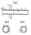
- a tubular element according to the invention indicated by 10 comprises a first tube 11 into which a second tube 12 is concentrically inserted with a gap of a few tenths of a millimetre.
- a series of longitudinal grooves 13 are formed in the outer surface of the second tube 12, and have a cross-section of essentially circular profile, obtained for example by milling followed by smoothing or polishing.
- the two tubes 11 and 12, inserted one into the other, are subjected to mechanical cold-drawing, effected with an Internal mandrel, which forces the two said tubes together to create positioning seats 14 for thermocouples 15.
- thermocouples 15 In the vicinity of an end portion 17 of said tubular element 10 constituted in this manner there are provided arcuate bores or seats 16 which connect the seats 14 to the outside of the tubular element to enable the thermocouples 15 to be connected to measuring systems (not shown).
- An end portion 17 of the tubular element 10 which is free from thermocouples 15 enables it to be assembled by welding, with the thermocouples 15 already inserted, these latter undergoing no danger of damage and emerging into a zone which is not exposed to the aggressive fluids, and lies beyond a wall 18.
- the drawing process carried out with an internal mandrel provides for a tube diameter reduction of 5-10% and a simultaneous analogous thickness reduction so that the two tubes remain strongly forced together to provide good thermal contact.
- the contacting surfaces ndergo chemical pickling treatment and the surfaces which slide in the drawbench undergo bonderizing.
- a series of longitudinal welds can be provided in suitable number, made for example by means of an electron beam or a similar method.
Landscapes
- Physics & Mathematics (AREA)
- General Physics & Mathematics (AREA)
- Measuring Temperature Or Quantity Of Heat (AREA)
- Monitoring And Testing Of Nuclear Reactors (AREA)
Priority Applications (3)
| Application Number | Priority Date | Filing Date | Title |
|---|---|---|---|
| AT84201950T ATE48189T1 (de) | 1984-12-28 | 1984-12-28 | Rohrfoermige, mit temperaturfuehlern bestueckte vorrichtung, insbesondere zur messung von uebertemperaturen in den ueberhitzerrohren von waermekraftanlagen. |
| DE8484201950T DE3480559D1 (en) | 1984-12-28 | 1984-12-28 | Tubular element instrumented with temperature sensors, in particular for measuring overtemperatures in the tubes of thermoelectric power plant superheaters |
| EP84201950A EP0185804B1 (de) | 1984-12-28 | 1984-12-28 | Rohrförmige, mit Temperaturfühlern bestückte Vorrichtung, insbesondere zur Messung von Übertemperaturen in den Überhitzerrohren von Wärmekraftanlagen |
Applications Claiming Priority (1)
| Application Number | Priority Date | Filing Date | Title |
|---|---|---|---|
| EP84201950A EP0185804B1 (de) | 1984-12-28 | 1984-12-28 | Rohrförmige, mit Temperaturfühlern bestückte Vorrichtung, insbesondere zur Messung von Übertemperaturen in den Überhitzerrohren von Wärmekraftanlagen |
Publications (2)
| Publication Number | Publication Date |
|---|---|
| EP0185804A1 true EP0185804A1 (de) | 1986-07-02 |
| EP0185804B1 EP0185804B1 (de) | 1989-11-23 |
Family
ID=8192509
Family Applications (1)
| Application Number | Title | Priority Date | Filing Date |
|---|---|---|---|
| EP84201950A Expired EP0185804B1 (de) | 1984-12-28 | 1984-12-28 | Rohrförmige, mit Temperaturfühlern bestückte Vorrichtung, insbesondere zur Messung von Übertemperaturen in den Überhitzerrohren von Wärmekraftanlagen |
Country Status (3)
| Country | Link |
|---|---|
| EP (1) | EP0185804B1 (de) |
| AT (1) | ATE48189T1 (de) |
| DE (1) | DE3480559D1 (de) |
Cited By (1)
| Publication number | Priority date | Publication date | Assignee | Title |
|---|---|---|---|---|
| GB2329023A (en) * | 1997-09-09 | 1999-03-10 | Thermocouple Instr Limited | A ring shaped temperature sensor mounting for inside a pipeway. |
Citations (5)
| Publication number | Priority date | Publication date | Assignee | Title |
|---|---|---|---|---|
| GB671734A (en) * | 1949-03-01 | 1952-05-07 | Pyrometrie Ind | Improvements in or relating to electric circuits |
| GB909187A (en) * | 1959-09-29 | 1962-10-24 | Resistoflex Corp | Dip pipe assembly |
| FR1409535A (fr) * | 1963-08-19 | 1965-08-27 | Procédé et dispositif pour déterminer l'écoulement d'un fluide | |
| US3212178A (en) * | 1960-12-16 | 1965-10-19 | Atomic Energy Authority Uk | Process of assembling a temperature measuring device within an aperture of a fuel element |
| US4023411A (en) * | 1975-11-05 | 1977-05-17 | Hans Escher | Temperature measuring device |
-
1984
- 1984-12-28 AT AT84201950T patent/ATE48189T1/de active
- 1984-12-28 DE DE8484201950T patent/DE3480559D1/de not_active Expired
- 1984-12-28 EP EP84201950A patent/EP0185804B1/de not_active Expired
Patent Citations (5)
| Publication number | Priority date | Publication date | Assignee | Title |
|---|---|---|---|---|
| GB671734A (en) * | 1949-03-01 | 1952-05-07 | Pyrometrie Ind | Improvements in or relating to electric circuits |
| GB909187A (en) * | 1959-09-29 | 1962-10-24 | Resistoflex Corp | Dip pipe assembly |
| US3212178A (en) * | 1960-12-16 | 1965-10-19 | Atomic Energy Authority Uk | Process of assembling a temperature measuring device within an aperture of a fuel element |
| FR1409535A (fr) * | 1963-08-19 | 1965-08-27 | Procédé et dispositif pour déterminer l'écoulement d'un fluide | |
| US4023411A (en) * | 1975-11-05 | 1977-05-17 | Hans Escher | Temperature measuring device |
Cited By (1)
| Publication number | Priority date | Publication date | Assignee | Title |
|---|---|---|---|---|
| GB2329023A (en) * | 1997-09-09 | 1999-03-10 | Thermocouple Instr Limited | A ring shaped temperature sensor mounting for inside a pipeway. |
Also Published As
| Publication number | Publication date |
|---|---|
| EP0185804B1 (de) | 1989-11-23 |
| ATE48189T1 (de) | 1989-12-15 |
| DE3480559D1 (en) | 1989-12-28 |
Similar Documents
| Publication | Publication Date | Title |
|---|---|---|
| US4671675A (en) | Tubular element instrumented with temperature sensors, in particular for measuring overtemperatures in the tubes of thermoelectric power plant superheaters | |
| US4153875A (en) | Eddy-current testing device for metal tubes which are bent at least locally | |
| US4694864A (en) | Double-wall tube for a heat exchanger | |
| EP0015712A1 (de) | Verfahren zur Herstellung zusammengesetzter mehrwandiger Rohre | |
| EP3844464B1 (de) | Temperatursensorsystem | |
| CN102901748B (zh) | 一种基于管道温度场分布的无损检测方法 | |
| JP2011073059A (ja) | 金属二重管の製造方法 | |
| HUP9903669A2 (hu) | Hőmérsékletmérő szonda | |
| Joshi et al. | An analysis of combined free and forced convection heat transfer from a horizontal circular cylinder to a transverse flow | |
| US4023411A (en) | Temperature measuring device | |
| CN115717944A (zh) | 直接测温式cot表面热电偶 | |
| JPS58783A (ja) | ガンマ線センサのための多接点熱電対 | |
| EP0185804B1 (de) | Rohrförmige, mit Temperaturfühlern bestückte Vorrichtung, insbesondere zur Messung von Übertemperaturen in den Überhitzerrohren von Wärmekraftanlagen | |
| US5074672A (en) | Arrangement for monitoring temperatures of water-cooled electric generator windings | |
| EP0165675B1 (de) | Vorrichtung zur Messung der thermischen Beanspruchung eines unter Druck stehenden Rohres | |
| US5146786A (en) | Rotary union for use with ultrasonic thickness measuring probe | |
| JPS6321129B2 (de) | ||
| Bullen et al. | A study of turbulent flow in pipe contractions | |
| US4559436A (en) | Heat exchanger tube repair | |
| EP0128644B1 (de) | Reparieren von Wärmetauscherrohren | |
| EP4310434B1 (de) | Wärmetauscher mit faseroptischem sensor zur bestimmung einer rohrwanddicke eines wärmeübertragungsrohres des wärmetauschers und verfahren zum betreiben eines solchen wärmetauschers | |
| CN2287719Y (zh) | 汽包与测量装置之间多测孔接管 | |
| Tidball et al. | Thermal-Shocking Austenitic Stainless Steels With Molten Metals | |
| Cohn et al. | Nonintrusive inspection for flow-accelerated corrosion detection | |
| JPH05223658A (ja) | 流体流通管路における温度異常検出構造 |
Legal Events
| Date | Code | Title | Description |
|---|---|---|---|
| PUAI | Public reference made under article 153(3) epc to a published international application that has entered the european phase |
Free format text: ORIGINAL CODE: 0009012 |
|
| AK | Designated contracting states |
Kind code of ref document: A1 Designated state(s): AT BE CH DE FR GB LI LU NL SE |
|
| 17P | Request for examination filed |
Effective date: 19861021 |
|
| 17Q | First examination report despatched |
Effective date: 19880321 |
|
| GRAA | (expected) grant |
Free format text: ORIGINAL CODE: 0009210 |
|
| AK | Designated contracting states |
Kind code of ref document: B1 Designated state(s): AT BE CH DE FR GB LI LU NL SE |
|
| PG25 | Lapsed in a contracting state [announced via postgrant information from national office to epo] |
Ref country code: SE Effective date: 19891123 Ref country code: NL Effective date: 19891123 Ref country code: LI Effective date: 19891123 Ref country code: CH Effective date: 19891123 Ref country code: BE Effective date: 19891123 Ref country code: AT Effective date: 19891123 |
|
| REF | Corresponds to: |
Ref document number: 48189 Country of ref document: AT Date of ref document: 19891215 Kind code of ref document: T |
|
| REF | Corresponds to: |
Ref document number: 3480559 Country of ref document: DE Date of ref document: 19891228 |
|
| PG25 | Lapsed in a contracting state [announced via postgrant information from national office to epo] |
Ref country code: LU Free format text: LAPSE BECAUSE OF NON-PAYMENT OF DUE FEES Effective date: 19891231 |
|
| REG | Reference to a national code |
Ref country code: CH Ref legal event code: PL |
|
| ET | Fr: translation filed | ||
| NLV1 | Nl: lapsed or annulled due to failure to fulfill the requirements of art. 29p and 29m of the patents act | ||
| PLBE | No opposition filed within time limit |
Free format text: ORIGINAL CODE: 0009261 |
|
| STAA | Information on the status of an ep patent application or granted ep patent |
Free format text: STATUS: NO OPPOSITION FILED WITHIN TIME LIMIT |
|
| 26N | No opposition filed | ||
| PGFP | Annual fee paid to national office [announced via postgrant information from national office to epo] |
Ref country code: FR Payment date: 19981209 Year of fee payment: 15 |
|
| PGFP | Annual fee paid to national office [announced via postgrant information from national office to epo] |
Ref country code: GB Payment date: 19981231 Year of fee payment: 15 |
|
| PGFP | Annual fee paid to national office [announced via postgrant information from national office to epo] |
Ref country code: DE Payment date: 19990107 Year of fee payment: 15 |
|
| PG25 | Lapsed in a contracting state [announced via postgrant information from national office to epo] |
Ref country code: GB Free format text: LAPSE BECAUSE OF NON-PAYMENT OF DUE FEES Effective date: 19991228 |
|
| GBPC | Gb: european patent ceased through non-payment of renewal fee |
Effective date: 19991228 |
|
| PG25 | Lapsed in a contracting state [announced via postgrant information from national office to epo] |
Ref country code: FR Free format text: LAPSE BECAUSE OF NON-PAYMENT OF DUE FEES Effective date: 20000831 |
|
| PG25 | Lapsed in a contracting state [announced via postgrant information from national office to epo] |
Ref country code: DE Free format text: LAPSE BECAUSE OF NON-PAYMENT OF DUE FEES Effective date: 20001003 |
|
| REG | Reference to a national code |
Ref country code: FR Ref legal event code: ST |