EP0185842A1 - Dispositif pour accoupler un porte-outil échangeable à une broche - Google Patents
Dispositif pour accoupler un porte-outil échangeable à une broche Download PDFInfo
- Publication number
- EP0185842A1 EP0185842A1 EP85109949A EP85109949A EP0185842A1 EP 0185842 A1 EP0185842 A1 EP 0185842A1 EP 85109949 A EP85109949 A EP 85109949A EP 85109949 A EP85109949 A EP 85109949A EP 0185842 A1 EP0185842 A1 EP 0185842A1
- Authority
- EP
- European Patent Office
- Prior art keywords
- bore
- wedge pieces
- cam
- spindle
- actuating rod
- Prior art date
- Legal status (The legal status is an assumption and is not a legal conclusion. Google has not performed a legal analysis and makes no representation as to the accuracy of the status listed.)
- Granted
Links
Images


Classifications
-
- B—PERFORMING OPERATIONS; TRANSPORTING
- B23—MACHINE TOOLS; METAL-WORKING NOT OTHERWISE PROVIDED FOR
- B23B—TURNING; BORING
- B23B31/00—Chucks; Expansion mandrels; Adaptations thereof for remote control
- B23B31/02—Chucks
- B23B31/24—Chucks characterised by features relating primarily to remote control of the gripping means
- B23B31/26—Chucks characterised by features relating primarily to remote control of the gripping means using mechanical transmission through the working-spindle
- B23B31/261—Chucks characterised by features relating primarily to remote control of the gripping means using mechanical transmission through the working-spindle clamping the end of the toolholder shank
-
- B—PERFORMING OPERATIONS; TRANSPORTING
- B23—MACHINE TOOLS; METAL-WORKING NOT OTHERWISE PROVIDED FOR
- B23B—TURNING; BORING
- B23B31/00—Chucks; Expansion mandrels; Adaptations thereof for remote control
- B23B31/02—Chucks
- B23B31/10—Chucks characterised by the retaining or gripping devices or their immediate operating means
- B23B31/107—Retention by laterally-acting detents, e.g. pins, screws, wedges; Retention by loose elements, e.g. balls
- B23B31/1072—Retention by axially or circumferentially oriented cylindrical elements
-
- B—PERFORMING OPERATIONS; TRANSPORTING
- B23—MACHINE TOOLS; METAL-WORKING NOT OTHERWISE PROVIDED FOR
- B23B—TURNING; BORING
- B23B31/00—Chucks; Expansion mandrels; Adaptations thereof for remote control
- B23B31/02—Chucks
- B23B31/10—Chucks characterised by the retaining or gripping devices or their immediate operating means
- B23B31/107—Retention by laterally-acting detents, e.g. pins, screws, wedges; Retention by loose elements, e.g. balls
- B23B31/1078—Retention by wedges
Definitions
- the invention relates to a device for connecting an interchangeable tool head to the spindle of a numerically controlled machine tool, with a pin which is concentric with the spindle axis and which engages in a correspondingly dimensioned bore and in which a plurality of wedge pieces
- actuating device for adjusting the wedge pieces between a clamping position, in which they engage with bevelled surfaces in correspondingly bevelled recesses in the bore wall in order to close an annular end face adjacent to the pin against an annular end face adjacent to the bore pull, and a release position in which the wedge pieces are moved radially inwards out of the recesses in the bore wall in order to be able to pull the pin out of the bore for the tool change.
- the actuating device consists of a threaded bolt which is screwed into the threaded holes of the two wedge pieces with opposite threads. Lateral openings are provided for rotating the threaded bolt and thus for the radial adjustment of the two wedge pieces, through which the threaded bolt can be grasped by a manually or mechanically operated key. Adjusting the wedge pieces from the side is sometimes disadvantageous. The clamping forces must not be made too large due to the threaded connection between the threaded bolt and the wedge pieces. Furthermore, a coolant supply through the threaded bolt to the tool is not possible.
- the invention has for its object to provide a device of the type mentioned that it can be operated centrally and can be easily solved despite high clamping forces.
- the actuating device comprises a cam device via which the wedge pieces are connected to an actuating rod which is concentric with the spindle axis and can be moved back and forth, and in that the cam device has cam projections which correspond to the actuating rod or are assigned to the wedge pieces and in appropriately designed cam grooves of the wedge pieces or the Be Actuating rod are positively guided in order to be able to adjust the wedge pieces in both radial directions.
- the wedge pieces are positively guided in both radial adjustment directions by the cam device provided according to the invention.
- the two wedge pieces are therefore adjusted not only in the clamping direction but also in the release direction by the actuating rod, so that the wedge pieces are already in their release position when the tool head is removed.
- the tool head can thus be removed from the spindle in a particularly convenient and simple manner.
- a particular advantage of the device designed according to the invention is that it can be used with tool heads with standard dimensions, so that it can be used in conjunction with conventional tool handling and gripping systems and with conventional magazines. Not even a special spindle adjustment is required if the device designed according to the invention is provided between an attachment flange part fastened to the spindle and the tool head.
- Another advantage of the device designed according to the invention is that it enables coolant to be supplied to the tool in a simple manner with the aid of central bores.
- the invention is characterized by simple construction, high functional reliability and ease of use.
- a tool head 4 is interchangeably attached to a rotatably mounted spindle 2 of a numerically controlled machine tool (not shown) by means of a connecting device 6.
- the tool head 4 is, for example, a boring bar, but can also be another rotating tool.
- the connecting device 6 comprises a flange 8 attached to the rear end of the tool head 4, from which a cylindrical pin 10, which is concentric with the spindle axis, extends.
- the pin 10 is fitted into a correspondingly formed bore 12 of the spindle 2.
- two diametrically opposed wedge pieces 16 are radially displaceably mounted.
- the wedge pieces 16 are adjustable between a radially outer clamping position and a radially inner release position.
- the wedge pieces 16 are in their clamping position, in which they engage with their radially outer ends in a recess 18 in the wall of the bore 12.
- they are pressed with chamfered surfaces 20 against chamfered surfaces 22 of the depressions 18, so that they exert clamping forces on the pin 10, which seek to pull the pin 10 into the bore 12.
- the mutually facing end faces 21, 23 of the flange 8 and the spindle 2 lying in radial planes are pressed against one another.
- a cam device 24 is provided which is actuated via a centrally arranged actuating rod 26 which can be moved back and forth by a power drive.
- the cam device 24 comprises an armature 28 which is arranged in an extension and coaxial to the actuating rod 26 and on which a cam part 30 is formed.
- the cam part 30 is arranged radially inside the wedge pieces 16 in a recess 29 of the pin 10 (see also FIG. 2) and is provided on opposite sides with two cam lugs 32 which run obliquely to the spindle axis and which are guided in cam grooves 34 of the two wedge pieces 16.
- the cam lugs 32 and the cam groove 34 have an approximately T-shaped cross section, so that the two wedge pieces 16 can be adjusted by the cam part 30 in opposite directions of movement.
- Figure 3 shows that the cam lugs 32 and the cam grooves 34 each have an area 36 of a larger pitch and an area 38 of a smaller pitch.
- the areas 36 with a larger pitch ensure an accelerated radial stroke of the wedge pieces 16, while the areas 38 with a smaller pitch are used to generate the correspondingly large clamping forces.
- the armature 28 formed on the other end of the cam part 30 is connected to the actuating rod 26 via an automatically actuatable coupling 44. Since the design of the clutch 44 can be conventional, it will not be described in detail. It should only be mentioned that the clutch 44 is automatically disengaged when the actuating rod 26 is shifted to the left (in FIG. 1) so that the armature 28 is released from the actuating rod 26, while when the actuating rod 26 is moved back to the right (in FIG. 1) ) the clutch 44 is automatically engaged to connect the armature 28 to the actuating rod 26.
- a sleeve part 46 is screwed, on the free end of which a support ring 48 is attached.
- the support ring 48 serves to support a helical compression spring 50, which prestresses the cam part 30 and thus the wedge pieces 16 in their release position.
- a coolant channel 52 which opens into the coolant bore 42 of the tool head 4, extends through the actuating rod 26, the armature 28, the cam part 30 and the guide pin 40, so that the tool (not shown) can be supplied with coolant in a simple manner.
- the pin 10 is cylindrical, comparatively large contact surfaces are available in the area of the end faces 21, 23, which means that the length of the e.g. designed as a boring bar tool head 4.
- the pin 10 could also be conical, so that it could be received in the usual conical receptacle of the spindle 2.
- the actuating rod 26 executes a working stroke to the left, for example under the control of a hydraulic motor (not shown).
- a hydraulic motor not shown
- the armature 28 and the cam part 30 are shifted to the left by a corresponding amount, as a result of which the wedge pieces 16 are radially inwardly from the cam device 24 be pulled until they have completely left the recesses 18 of the pin 10.
- the clutch 44 is disengaged so that the armature 28 is released from the actuating rod 26.
- the tool head 4 including the cam device 24, the armature 28, the sleeve part 46, the support ring 48 and the spring 50 can now be pulled off the spindle 2 with relatively little effort.
- the tool head 4 can now be moved to a tool magazine with the aid of a conventional handling and gripper system and can be exchanged there for another tool head 4.
- the spring 50 presses the cam part 30 and thus the wedge pieces 16 into their release position, so that the wedge pieces 16 cannot be lost.
- the actuating rod 16 When the new tool head 4 is inserted with its pin 10 into the bore 12, the actuating rod 16 is moved to the right (in FIG. 1), as a result of which the coupling 44 is engaged and the wedge pieces 16 are extended radially. Because of the differently inclined areas 36, 38 of the cam lugs 32 and cam grooves 34 (FIG. 3), the radially outward movement of the wedge pieces 16 initially takes place quickly and more slowly at the end of the range of motion, but correspondingly large clamping forces are generated in this end area of the motion. The connecting device 6 is then again in its clamping position, in which it securely connects the tool head 4 to the spindle 2.
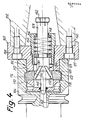
- FIG. 4 A somewhat modified embodiment of the connecting device shown in FIG. 1 is shown in FIG. 4, individual parts corresponding to FIG. 1 are designated by the same reference numbers, but increased by 100.
- the basic structure of the connecting device 106 with the cam device 124 including the armature 128 is the same as in the embodiment according to FIG. 1.
- the essential difference between the embodiment shown in FIG. 4 and that according to FIG. 1 is that in FIG 4, the pin 110 is not attached to the tool head, but to a separate attachment flange part 160, which is fastened to the spindle 102 by means of screws 162.
- the bore 112 receiving the pin 110 is in this case formed on the tool head 104.
- a further advantage of the embodiment according to FIG. 4 is that when the tool head 104 is removed in the released position of the connecting device 106, the attachment flange part 160, including the cam device 124, the armature 128 and the other associated parts, remain on the spindle 102. In this case, therefore, there is no need to provide an automatically releasable coupling between the armature 128 and the actuating rod. Also, a spring 150 is not absolutely necessary, since when the tool head 104 is removed, the wedge pieces 116 are provided over those provided on the machine Drive (not shown) can be held in its radially retracted release position. Otherwise, the mode of operation is the same as in the exemplary embodiment according to FIG. 1.
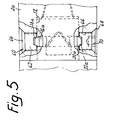
- each wear part 60 has a threaded shaft 62 and a head section 64.
- the threaded shaft 62 is screwed into a radially extending threaded bore 66 of the bore wall, while the conical head section 64 abuts a correspondingly conical bearing surface 68 adjacent to the threaded bore 66.
- Each wear part 60 is provided with an externally accessible key receptacle 70. As a result, the wearing parts 60 can be screwed into the threaded bores 66 until their head sections 64 abut the conical contact surfaces 68. The wearing parts 60 are thus fixed radially and axially with respect to the bore 12a.
- the wear parts are provided on their end facing the interior of the bore 12a with the recess 18a, the beveled surface 22a is conical in the present embodiment.
- the tapered surface 20a of the wedge pieces 16a is also conical.
Landscapes
- Engineering & Computer Science (AREA)
- Mechanical Engineering (AREA)
- Gripping On Spindles (AREA)
- Cutting Tools, Boring Holders, And Turrets (AREA)
Priority Applications (1)
| Application Number | Priority Date | Filing Date | Title |
|---|---|---|---|
| AT85109949T ATE37814T1 (de) | 1984-12-19 | 1985-08-07 | Einrichtung zum verbinden eines auswechselbaren werkzeugkopfes mit einer werkzeugspindel. |
Applications Claiming Priority (4)
| Application Number | Priority Date | Filing Date | Title |
|---|---|---|---|
| DE3446368 | 1984-12-19 | ||
| DE3446368 | 1984-12-19 | ||
| DE19853522555 DE3522555A1 (de) | 1984-12-19 | 1985-06-24 | Einrichtung zum verbinden eines auswechselbaren werkzeugkopfes mit einer werkzeugspindel |
| DE3522555 | 1985-06-24 |
Publications (3)
| Publication Number | Publication Date |
|---|---|
| EP0185842A1 true EP0185842A1 (fr) | 1986-07-02 |
| EP0185842B1 EP0185842B1 (fr) | 1988-10-12 |
| EP0185842B2 EP0185842B2 (fr) | 1992-07-01 |
Family
ID=25827528
Family Applications (1)
| Application Number | Title | Priority Date | Filing Date |
|---|---|---|---|
| EP85109949A Expired - Lifetime EP0185842B2 (fr) | 1984-12-19 | 1985-08-07 | Dispositif pour accoupler un porte-outil échangeable à une broche |
Country Status (3)
| Country | Link |
|---|---|
| EP (1) | EP0185842B2 (fr) |
| CA (1) | CA1255088A (fr) |
| DE (2) | DE3522555A1 (fr) |
Cited By (10)
| Publication number | Priority date | Publication date | Assignee | Title |
|---|---|---|---|---|
| EP0275441A1 (fr) * | 1986-12-23 | 1988-07-27 | Hertel Aktiengesellschaft Werkzeuge + Hartstoffe | Dispositif de serrage |
| DE3709299A1 (de) * | 1987-03-20 | 1988-09-29 | Index Werke Kg Hahn & Tessky | Werkzeugwechseleinrichtung fuer eine werkzeugmaschine |
| EP0310942A1 (fr) * | 1987-10-08 | 1989-04-12 | Hertel Aktiengesellschaft Werkzeuge + Hartstoffe | Dispositif de changement et de serrage d'une tête d'outil à une broche d'une machine-outils |
| FR2638991A1 (fr) * | 1988-11-15 | 1990-05-18 | Pfalzgraf Emile Epb Sa | Dispositif de montage a queue conique, en particulier au cone 7/24, a application cone et face pour attachements, porte-outils et outils |
| EP0373086A1 (fr) * | 1988-11-15 | 1990-06-13 | Emile Pfalzgraf "Epb", S.A. | Dispositif de montage à queue conique, en particulier au cône 7/24e,à application cône et face pour attachements, porte-outils et outils |
| EP0386522A3 (fr) * | 1989-03-01 | 1991-01-09 | GÖLTENBODT PRÄZISIONS-WERKZEUG-UND MASCHINENFABRIK GmbH & CO. | Dispositif pour le changement et le serrage d'outil |
| US5433562A (en) * | 1993-12-03 | 1995-07-18 | J. D. Phillips Corporation | Cutter quick change system |
| EP0685327A1 (fr) * | 1994-06-03 | 1995-12-06 | Wilhelm Fette GmbH | Poinçon pour une machine de fabrication de comprimés |
| EP1579948A1 (fr) * | 2004-03-22 | 2005-09-28 | Schunk GmbH & Co. KG Spann- und Greiftechnik | Dispositif de serrage |
| CN108436515A (zh) * | 2018-03-23 | 2018-08-24 | 昆山冠品优精密机械有限公司 | 快速装夹夹头 |
Families Citing this family (4)
| Publication number | Priority date | Publication date | Assignee | Title |
|---|---|---|---|---|
| DE3839681A1 (de) * | 1987-11-24 | 1989-06-15 | Komet Stahlhalter Werkzeug | Vorrichtung zum verbinden eines werkzeughalters mit einem traeger, insbesondere einer werkzeugmaschinenspindel |
| DE3831666A1 (de) * | 1988-09-17 | 1990-03-29 | Krupp Widia Gmbh | Vorsatzflansch fuer eine bohr-, fraes- oder bohr-fraes-werkzeugmaschinenspindel |
| DE4024644A1 (de) * | 1989-09-09 | 1991-03-14 | Komet Stahlhalter Werkzeug | Vorrichtung zum loesbaren verbinden eines werkzeugs mit einer maschinenspindel |
| DE4110857A1 (de) * | 1991-04-04 | 1992-10-08 | Kuehn Joachim Dipl Ing | Einrichtung zum kuppeln eines werkzeughalters mit der arbeitsspindel einer werkzeugmaschine |
Citations (3)
| Publication number | Priority date | Publication date | Assignee | Title |
|---|---|---|---|---|
| CH504930A (de) * | 1969-02-10 | 1971-03-31 | Kearney & Trecker Corp | Werkzeugmaschine |
| DE1777019B2 (de) * | 1967-08-25 | 1979-11-29 | Kearney & Trecker Corp., Milwaukee, Wis. (V.St.A.) | Werkzeugmaschine mit einer Werkzeugwechseleinrichtung |
| DE1752833B2 (de) * | 1967-07-29 | 1981-07-02 | Ing. C. Olivetti & C., S.p.A., 10015 Ivrea, Torino | Verriegelungseinrichtung für die Werkzeuge im Werkzeugmagazin einer Werkzeugmaschine |
Family Cites Families (2)
| Publication number | Priority date | Publication date | Assignee | Title |
|---|---|---|---|---|
| US1361773A (en) * | 1918-03-08 | 1920-12-07 | Raison Alfred | Piston-chuck |
| US4573824A (en) * | 1984-02-10 | 1986-03-04 | Gte Products Corporation | Apparatus for coupling a first member to a second member |
-
1985
- 1985-06-24 DE DE19853522555 patent/DE3522555A1/de not_active Ceased
- 1985-08-07 EP EP85109949A patent/EP0185842B2/fr not_active Expired - Lifetime
- 1985-08-07 DE DE8585109949T patent/DE3565486D1/de not_active Expired
- 1985-12-18 CA CA000497991A patent/CA1255088A/fr not_active Expired
Patent Citations (3)
| Publication number | Priority date | Publication date | Assignee | Title |
|---|---|---|---|---|
| DE1752833B2 (de) * | 1967-07-29 | 1981-07-02 | Ing. C. Olivetti & C., S.p.A., 10015 Ivrea, Torino | Verriegelungseinrichtung für die Werkzeuge im Werkzeugmagazin einer Werkzeugmaschine |
| DE1777019B2 (de) * | 1967-08-25 | 1979-11-29 | Kearney & Trecker Corp., Milwaukee, Wis. (V.St.A.) | Werkzeugmaschine mit einer Werkzeugwechseleinrichtung |
| CH504930A (de) * | 1969-02-10 | 1971-03-31 | Kearney & Trecker Corp | Werkzeugmaschine |
Cited By (12)
| Publication number | Priority date | Publication date | Assignee | Title |
|---|---|---|---|---|
| EP0275441A1 (fr) * | 1986-12-23 | 1988-07-27 | Hertel Aktiengesellschaft Werkzeuge + Hartstoffe | Dispositif de serrage |
| DE3709299A1 (de) * | 1987-03-20 | 1988-09-29 | Index Werke Kg Hahn & Tessky | Werkzeugwechseleinrichtung fuer eine werkzeugmaschine |
| EP0310942A1 (fr) * | 1987-10-08 | 1989-04-12 | Hertel Aktiengesellschaft Werkzeuge + Hartstoffe | Dispositif de changement et de serrage d'une tête d'outil à une broche d'une machine-outils |
| US4863323A (en) * | 1987-10-08 | 1989-09-05 | Hertel Ag Werkzeuge+Hartstoffe | Changing and chucking tool |
| FR2638991A1 (fr) * | 1988-11-15 | 1990-05-18 | Pfalzgraf Emile Epb Sa | Dispositif de montage a queue conique, en particulier au cone 7/24, a application cone et face pour attachements, porte-outils et outils |
| EP0373086A1 (fr) * | 1988-11-15 | 1990-06-13 | Emile Pfalzgraf "Epb", S.A. | Dispositif de montage à queue conique, en particulier au cône 7/24e,à application cône et face pour attachements, porte-outils et outils |
| US5030047A (en) * | 1988-11-15 | 1991-07-09 | E.P.B. Emile Pfalzgraf, Societe Anonyme | Mounting device for conical shank |
| EP0386522A3 (fr) * | 1989-03-01 | 1991-01-09 | GÖLTENBODT PRÄZISIONS-WERKZEUG-UND MASCHINENFABRIK GmbH & CO. | Dispositif pour le changement et le serrage d'outil |
| US5433562A (en) * | 1993-12-03 | 1995-07-18 | J. D. Phillips Corporation | Cutter quick change system |
| EP0685327A1 (fr) * | 1994-06-03 | 1995-12-06 | Wilhelm Fette GmbH | Poinçon pour une machine de fabrication de comprimés |
| EP1579948A1 (fr) * | 2004-03-22 | 2005-09-28 | Schunk GmbH & Co. KG Spann- und Greiftechnik | Dispositif de serrage |
| CN108436515A (zh) * | 2018-03-23 | 2018-08-24 | 昆山冠品优精密机械有限公司 | 快速装夹夹头 |
Also Published As
| Publication number | Publication date |
|---|---|
| EP0185842B2 (fr) | 1992-07-01 |
| EP0185842B1 (fr) | 1988-10-12 |
| DE3565486D1 (en) | 1988-11-17 |
| CA1255088A (fr) | 1989-06-06 |
| DE3522555A1 (de) | 1986-06-26 |
Similar Documents
| Publication | Publication Date | Title |
|---|---|---|
| EP0369211B1 (fr) | Dispositif de serrage pour assembler une tête d'outillage et un porte-outil dans des machines-outils | |
| EP0185842B1 (fr) | Dispositif pour accoupler un porte-outil échangeable à une broche | |
| DE3936122C1 (fr) | ||
| DE3324312C2 (de) | Werkzeugmaschine mit Werkzeugwechselvorrichtung | |
| DE3406490A1 (de) | Auswechselbarer werkzeugkopf fuer eine numerisch gesteuerte werkzeugmaschine | |
| EP0507147A1 (fr) | Accouplement | |
| CH622202A5 (fr) | ||
| EP0235511A2 (fr) | Accouplement de liaison d'une tête d'outil et d'un porte-outil à une machine-outil avec une tête d'outil interchangeable | |
| DE2729939A1 (de) | Kraftbetaetigtes spannfutter | |
| EP0086379B1 (fr) | Mécanisme de changement d'outil | |
| DE2533803B2 (de) | Kraftbetätigtes Keilspannfutter | |
| EP0350516B1 (fr) | Dispositif de changement rapide de mandrins | |
| DD297098A5 (de) | Vorrichtung zum loesbaren verbinden eines werkzeugs mit einer maschinenspindel | |
| EP0458170A2 (fr) | Mandrin | |
| DE2723622A1 (de) | Pendelmesserkopf | |
| DE2831140A1 (de) | Spannzange | |
| DE69124284T2 (de) | Nietmaschine | |
| EP0173169A1 (fr) | Dispositif de blocage pivotant | |
| DE3427125C2 (de) | Teilbares Werkzeug für die spanabhebende Bearbeitung | |
| DE2647633C2 (de) | Werkzeughalter | |
| DE3437505A1 (de) | Selbstzentrierendes spannfutter mit einstellbaren und austauschbaren spannbacken | |
| EP0303002A1 (fr) | Mandrin de serrage | |
| DE8437207U1 (de) | Einrichtung zum Verbinden eines auswechselbaren Werkzeugkopfes mit einer Werkzeugspindel | |
| DE3341252A1 (de) | Automatische werkzeugwechseleinrichtung | |
| DE3418553A1 (de) | Vorrichtung zum schnellwechseln der aufsatzbacken eines kraftbetaetigten spannfutters |
Legal Events
| Date | Code | Title | Description |
|---|---|---|---|
| PUAI | Public reference made under article 153(3) epc to a published international application that has entered the european phase |
Free format text: ORIGINAL CODE: 0009012 |
|
| AK | Designated contracting states |
Kind code of ref document: A1 Designated state(s): AT BE DE FR GB IT LU NL SE |
|
| 17P | Request for examination filed |
Effective date: 19861230 |
|
| 17Q | First examination report despatched |
Effective date: 19880223 |
|
| GRAA | (expected) grant |
Free format text: ORIGINAL CODE: 0009210 |
|
| AK | Designated contracting states |
Kind code of ref document: B1 Designated state(s): AT BE DE FR GB IT LU NL SE |
|
| REF | Corresponds to: |
Ref document number: 37814 Country of ref document: AT Date of ref document: 19881015 Kind code of ref document: T |
|
| ITF | It: translation for a ep patent filed | ||
| REF | Corresponds to: |
Ref document number: 3565486 Country of ref document: DE Date of ref document: 19881117 |
|
| GBT | Gb: translation of ep patent filed (gb section 77(6)(a)/1977) | ||
| ET | Fr: translation filed | ||
| PLBI | Opposition filed |
Free format text: ORIGINAL CODE: 0009260 |
|
| RAP2 | Party data changed (patent owner data changed or rights of a patent transferred) |
Owner name: GTE VALENITE CORPORATION |
|
| 26 | Opposition filed |
Opponent name: HERTEL AG WERKZEUGE + HARTSTOFFE Effective date: 19890708 Opponent name: KOMET STAHLHALTER- UND WERKZEUGFABRIK ROBERT BREU Effective date: 19890707 |
|
| ITPR | It: changes in ownership of a european patent |
Owner name: CAMBIO RAGIONE SOCIALE;GTE VALENITE CORPORATION |
|
| NLT1 | Nl: modifications of names registered in virtue of documents presented to the patent office pursuant to art. 16 a, paragraph 1 |
Owner name: GTE VALENITE CORPORATION TE TROY, MICHIGAN, VER. S |
|
| NLR1 | Nl: opposition has been filed with the epo |
Opponent name: HARTSTOFFE Opponent name: HERTEL AG WERKZEUGE Opponent name: KOMET STAHLHALTER- UND WERKZEUGFABRIK ROBERT BREUN |
|
| PLAB | Opposition data, opponent's data or that of the opponent's representative modified |
Free format text: ORIGINAL CODE: 0009299OPPO |
|
| R26 | Opposition filed (corrected) |
Opponent name: KOMET STAHLHALTER- UND WERKZEUGFABRIK ROBERT BREU Effective date: 19890707 |
|
| PUAH | Patent maintained in amended form |
Free format text: ORIGINAL CODE: 0009272 |
|
| STAA | Information on the status of an ep patent application or granted ep patent |
Free format text: STATUS: PATENT MAINTAINED AS AMENDED |
|
| 27A | Patent maintained in amended form |
Effective date: 19920701 |
|
| AK | Designated contracting states |
Kind code of ref document: B2 Designated state(s): AT BE DE FR GB IT LU NL SE |
|
| NLR2 | Nl: decision of opposition | ||
| ITTA | It: last paid annual fee | ||
| ITF | It: translation for a ep patent filed | ||
| ET3 | Fr: translation filed ** decision concerning opposition | ||
| NLR3 | Nl: receipt of modified translations in the netherlands language after an opposition procedure | ||
| GBTA | Gb: translation of amended ep patent filed (gb section 77(6)(b)/1977) | ||
| EPTA | Lu: last paid annual fee | ||
| ITPR | It: changes in ownership of a european patent |
Owner name: CAMBIO RAGIONE SOCIALE;VALENITE INC. |
|
| NLT1 | Nl: modifications of names registered in virtue of documents presented to the patent office pursuant to art. 16 a, paragraph 1 |
Owner name: VALENITE INC. TE TROY, MICHIGAN, VER. ST. V. AM. |
|
| REG | Reference to a national code |
Ref country code: FR Ref legal event code: CD |
|
| EAL | Se: european patent in force in sweden |
Ref document number: 85109949.9 |
|
| PGFP | Annual fee paid to national office [announced via postgrant information from national office to epo] |
Ref country code: GB Payment date: 19950727 Year of fee payment: 11 |
|
| PGFP | Annual fee paid to national office [announced via postgrant information from national office to epo] |
Ref country code: FR Payment date: 19950809 Year of fee payment: 11 |
|
| PGFP | Annual fee paid to national office [announced via postgrant information from national office to epo] |
Ref country code: AT Payment date: 19950811 Year of fee payment: 11 |
|
| PGFP | Annual fee paid to national office [announced via postgrant information from national office to epo] |
Ref country code: NL Payment date: 19950825 Year of fee payment: 11 |
|
| PGFP | Annual fee paid to national office [announced via postgrant information from national office to epo] |
Ref country code: BE Payment date: 19950926 Year of fee payment: 11 |
|
| PGFP | Annual fee paid to national office [announced via postgrant information from national office to epo] |
Ref country code: LU Payment date: 19951001 Year of fee payment: 11 |
|
| PG25 | Lapsed in a contracting state [announced via postgrant information from national office to epo] |
Ref country code: LU Free format text: LAPSE BECAUSE OF NON-PAYMENT OF DUE FEES Effective date: 19960807 Ref country code: GB Effective date: 19960807 Ref country code: AT Effective date: 19960807 |
|
| PG25 | Lapsed in a contracting state [announced via postgrant information from national office to epo] |
Ref country code: BE Effective date: 19960831 |
|
| BERE | Be: lapsed |
Owner name: VALENITE INC. Effective date: 19960831 |
|
| PG25 | Lapsed in a contracting state [announced via postgrant information from national office to epo] |
Ref country code: NL Effective date: 19970301 |
|
| GBPC | Gb: european patent ceased through non-payment of renewal fee |
Effective date: 19960807 |
|
| PG25 | Lapsed in a contracting state [announced via postgrant information from national office to epo] |
Ref country code: FR Effective date: 19970430 |
|
| NLV4 | Nl: lapsed or anulled due to non-payment of the annual fee |
Effective date: 19970301 |
|
| REG | Reference to a national code |
Ref country code: FR Ref legal event code: ST |
|
| PGFP | Annual fee paid to national office [announced via postgrant information from national office to epo] |
Ref country code: SE Payment date: 19970818 Year of fee payment: 13 Ref country code: DE Payment date: 19970818 Year of fee payment: 13 |
|
| PG25 | Lapsed in a contracting state [announced via postgrant information from national office to epo] |
Ref country code: SE Free format text: LAPSE BECAUSE OF NON-PAYMENT OF DUE FEES Effective date: 19980808 |
|
| EUG | Se: european patent has lapsed |
Ref document number: 85109949.9 |
|
| PG25 | Lapsed in a contracting state [announced via postgrant information from national office to epo] |
Ref country code: DE Free format text: LAPSE BECAUSE OF NON-PAYMENT OF DUE FEES Effective date: 19990601 |