EP0185900B1 - Dispositif de régulation du débit d'air pour ventilateurs - Google Patents
Dispositif de régulation du débit d'air pour ventilateurs Download PDFInfo
- Publication number
- EP0185900B1 EP0185900B1 EP85114200A EP85114200A EP0185900B1 EP 0185900 B1 EP0185900 B1 EP 0185900B1 EP 85114200 A EP85114200 A EP 85114200A EP 85114200 A EP85114200 A EP 85114200A EP 0185900 B1 EP0185900 B1 EP 0185900B1
- Authority
- EP
- European Patent Office
- Prior art keywords
- flaps
- openings
- pressure chamber
- ventilator
- aligned
- Prior art date
- Legal status (The legal status is an assumption and is not a legal conclusion. Google has not performed a legal analysis and makes no representation as to the accuracy of the status listed.)
- Expired
Links
Images


Classifications
-
- F—MECHANICAL ENGINEERING; LIGHTING; HEATING; WEAPONS; BLASTING
- F04—POSITIVE - DISPLACEMENT MACHINES FOR LIQUIDS; PUMPS FOR LIQUIDS OR ELASTIC FLUIDS
- F04D—NON-POSITIVE-DISPLACEMENT PUMPS
- F04D27/00—Control, e.g. regulation, of pumps, pumping installations or pumping systems specially adapted for elastic fluids
- F04D27/009—Control, e.g. regulation, of pumps, pumping installations or pumping systems specially adapted for elastic fluids by bleeding, by passing or recycling fluid
-
- F—MECHANICAL ENGINEERING; LIGHTING; HEATING; WEAPONS; BLASTING
- F05—INDEXING SCHEMES RELATING TO ENGINES OR PUMPS IN VARIOUS SUBCLASSES OF CLASSES F01-F04
- F05D—INDEXING SCHEME FOR ASPECTS RELATING TO NON-POSITIVE-DISPLACEMENT MACHINES OR ENGINES, GAS-TURBINES OR JET-PROPULSION PLANTS
- F05D2250/00—Geometry
- F05D2250/50—Inlet or outlet
- F05D2250/51—Inlet
Definitions
- the invention relates to a device on fans for ventilation systems with suction port integrated within the fan housing, in particular on radial fans, for regulating the air volume flow of the fan, with one or more openings being arranged on the intake, in the wall delimiting the suction chamber from the pressure chamber, the cross-sectional area of which can be varied by means of flaps attached to the openings, and the flaps are adjustable via linkage.
- This regulation of the air volume flow by means of the swirl is achieved in known systems by connecting a so-called swirl throttle upstream of the fan housing or the intake manifold.
- This upstream swirl throttle has guide vanes that are adjustable. Depending on the position of the guide vanes of the swirl throttle, the air flow sucked in via the suction nozzle receives a corresponding swirl, which allows the air flow to run in the circumferential direction or transverse to the axial direction of the fan.
- the effect of this is that the characteristic curve of the fan rises or falls depending on the position of the guide vanes of the swirl throttle.
- the fan drive speed remains constant across the entire control range. The fan's power requirement rises or falls accordingly when the characteristic curve changes, which means that considerable energy savings can be made in part-load operation of a system.
- the arrangement consists of a piece of pipe surrounding the suction line, which is connected to the pressure chamber.
- the pipe section has two openings lying opposite one another, which are covered by adjustable flaps. If the flaps covering the openings are opened, compressed air can flow from the pressure chamber of the fan housing via the pipe section surrounding the suction line through the opened openings into the suction line.
- the air flowing into the intake line creates a swirl in the intake air flow, which runs in the circumferential direction or transverse to the axial direction of the fan.
- This design of the swirl generation in the air flow sucked in by the fan within the intake line avoids the upstream connection of a swirl throttle which is very costly to produce, but uses a tube piece surrounding the intake line, which is connected upstream of the fan housing and in which flaps are arranged in a confined space, which are adjusted in this way must that the openings arranged between the pipe section and the suction line are covered or opened, which requires precise mechanics.
- This and the additional space required for the pipe section surrounding the suction line reveals a very complex design that cannot be used in the smallest of spaces. Elaborate design and large space requirements in the axial direction ultimately led to the fact that this design suggestion could not prevail in the construction of fans.
- the device according to the invention which does not require an upstream suction line, is particularly suitable in confined spaces in which the installation of known swirl devices would not be possible at all.
- the device according to the invention manages with fewer and easier to produce parts than is the case with a swirl throttle or an arrangement for hydraulic swirl distribution and can also be retrofitted in existing systems without requiring additional space. Further advantages of the object according to the invention are listed in the following description.
- Fig. 1 denotes a radial fan, on the suction surface 7 '(Fig. 2) in the suction port 6 a known swirl throttle 8 is arranged, with adjustable guide vanes 10 which are mounted at the points 9. Connected to the swirl throttle 8 is a longer or shorter pipeline 11, depending on the system, for sucking in the air flow.
- the impeller 3 of the fan 1 is attached to a shaft 4 (Fig. 2).
- the drive of the fan 1, which takes place via the shaft 4, is not shown.
- the pressure chamber 5 is located in the housing 2 of the fan 1.
- the pressure chamber 5 is sealed off from the suction surface 7 '(FIG. 2) by a suction nozzle 6 which tapers in the direction of the impeller.
- the suction nozzle 6 itself is firmly connected to the housing 2.
- Fig. 2 shows the arrangement described so far according to Fig. 1, seen from the side and shown schematically in section, so that the functional parts are visible. 2, the drive of the fan 1 via the shaft 4 is not shown.
- the guide vanes 1 of the swirl throttle 8 are shown in the open position and are in this position approximately parallel to the direction of flow of the air flow sucked in through the pipeline 11. If the guide vanes 10 are deflected from this position, a swirl is created behind the swirl throttle in the intake air flow, i.e. the swirl creates a flow that runs transversely to the axial direction and causes the characteristic curve of the fan 1 to be raised or lowered, the speed of the drive remaining constant during the raising or lowering of the characteristic curve of the fan 1.
- the power requirement of the fan 1 rises or falls accordingly when the characteristic curve is raised or lowered, as a result of which considerable energy savings are possible in part-load operation of a system.
- a cost-effectiveness analysis for the swirl throttle turns out to be particularly disadvantageous in that it causes losses even when it is fully open and that the drive motor consumes more power compared to a fan without a swirl throttle.
- the majority of swirl throttle constructions that have become known require tangible axial installation space. As FIG. 2 shows very clearly, for example, this swirl throttle requires a considerable amount of space, so that it is not possible at all to use a swirl throttle 8 when installation in a system is restricted.
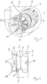
- Fig. 3 shows a fan 1 with a device according to the invention.
- the housing is denoted by 2, the paddle wheel by 3, the shaft by 4, the pressure chamber by 5 and the suction port which closes off the pressure chamber 5 from the suction surface 7 '(FIG. 4).
- the suction nozzle 6 which is firmly connected to the housing 2, one or more openings 12 are provided, which establish a connection between the pressure chamber 5 and the suction chamber 7 behind the suction nozzle 6.
- these openings 12 are provided with flaps 13 which are fastened to the suction port 6 via a joint 13 'and can be opened and closed in the direction of the pressure chamber 5 by means of a linkage, not shown, i.e. the size of the openings 12 vary from the "fully covered" position to the "fully open” position.
- FIG. 4 which shows a side view of the arrangement according to FIG. 3, the flap 13 (only one is visible) projects into the pressure chamber 5 in the open position. It works in two ways, firstly, when the fan 1 is started up in the pressure chamber 5 a pressure which, when the flap 13 is open, acts through the openings 12 in the suction nozzle 6 directly between the impeller 3 and the suction surface 7 ', that is to say in the suction space 7, on the air flow drawn in. This creates a swirl in the sucked-in air flow, immediately before entering the pressure chamber 5 via the paddle wheel, which, like a swirl throttle 8 (FIGS.
- the efficiency of the fan 1 with the device according to the invention is identical to the efficiency of a fan 1 without a swirl throttle 8 when the openings 12 in the suction nozzle 6 are closed and corresponds to the control device, ie the flap 13 in different open positions, when the device is activated Positions, the efficiency using a swirl throttle 8.
- FIGS. 3 and 4 show developments of the device according to the invention.
- Fig. 5 shows a paddle wheel with suction nozzle without housing in a perspective view.
- the reference numerals for the same parts are the same as in FIGS. 3 and 4.
- the openings 12 in the suction nozzle 6 are provided with a flap 14 which is located on the inside of the suction nozzle 6, that is to say in the suction chamber 7 , movably arranged via a joint 14, so that the openings 12 are completely closed with the flaps 14 or the flaps 14 are moved with any intermediate positions so that the surfaces of the openings 12 are completely open.
- FIG. 6 shows an embodiment of a fan 1 according to FIG. 5, seen from the side and drawn schematically in section, so that the functional parts can be clearly seen.
- the effects with flaps 14 closed or open over openings 12 are the same as described in detail in FIGS. 3 and 4.
- FIG. 7 shows a paddle wheel with a suction nozzle 6 without a housing in a perspective view.
- the same reference numerals have been used for the same parts as previously described.
- the further exemplary embodiment shown in FIGS. 7 and 8 shows, for opening or closing the openings 12, slides 15 which can slide in correspondingly arranged guideways 16 and 17, of which only one slider 15 can be seen in the illustration.
- These guideways 16 and 17, as shown in FIGS. 7 and 8, can be arranged both on the suction nozzle 6 within the pressure chamber 5 and on the inside of the suction nozzle 6 in the suction chamber 7.
- the slides 15 are adjustable by a linkage, not shown, from the completely closed position of the openings 12 through intermediate positions to the completely open surface of the openings 12.
- a plurality of slide 15 with corresponding guides 16 and 17 can also be arranged distributed over the circumference of the suction nozzle 6. Sufficient space is available in the pressure chamber 5 or in the suction chamber 7 behind the suction nozzle 6 to accommodate the mechanism (not shown) for adjusting the slide 15.
- FIG. 8 shows the exemplary embodiment according to the invention according to FIG. 7 seen from the side and shown schematically in section, so that the functional parts can be seen clearly.
- two or more sliders 15 with corresponding guideways 16 and 17 or other arrangements may be arranged. It is also conceivable to attach lugs 15 perpendicular to the surface of the sliders 15, the surfaces of which, like the leaves of the flaps 13 and 14 (FIGS. 3 to 6), act as ladles in the air flow.
Landscapes
- Engineering & Computer Science (AREA)
- Life Sciences & Earth Sciences (AREA)
- Sustainable Development (AREA)
- Mechanical Engineering (AREA)
- General Engineering & Computer Science (AREA)
- Structures Of Non-Positive Displacement Pumps (AREA)
- Jet Pumps And Other Pumps (AREA)
Claims (2)
Priority Applications (1)
| Application Number | Priority Date | Filing Date | Title |
|---|---|---|---|
| AT85114200T ATE43409T1 (de) | 1984-11-12 | 1985-11-07 | Vorrichtung an ventilatoren zur regelung des luftstromes. |
Applications Claiming Priority (2)
| Application Number | Priority Date | Filing Date | Title |
|---|---|---|---|
| DE3441295A DE3441295C2 (de) | 1984-11-12 | 1984-11-12 | Vorrichtung an Ventilatoren zur Regelung des Luftvolumenstromes |
| DE3441295 | 1984-11-12 |
Publications (2)
| Publication Number | Publication Date |
|---|---|
| EP0185900A1 EP0185900A1 (fr) | 1986-07-02 |
| EP0185900B1 true EP0185900B1 (fr) | 1989-05-24 |
Family
ID=6250087
Family Applications (1)
| Application Number | Title | Priority Date | Filing Date |
|---|---|---|---|
| EP85114200A Expired EP0185900B1 (fr) | 1984-11-12 | 1985-11-07 | Dispositif de régulation du débit d'air pour ventilateurs |
Country Status (3)
| Country | Link |
|---|---|
| EP (1) | EP0185900B1 (fr) |
| AT (1) | ATE43409T1 (fr) |
| DE (1) | DE3441295C2 (fr) |
Families Citing this family (2)
| Publication number | Priority date | Publication date | Assignee | Title |
|---|---|---|---|---|
| CN111963456B (zh) * | 2020-08-12 | 2021-12-14 | 库车县榆树岭煤矿有限责任公司 | 一种基于矿井用可以自行调节进风量的通风装置 |
| CN113700666B (zh) * | 2021-09-30 | 2024-02-02 | 郑州德玛电气有限公司 | 一种风力可调的离心散热风机 |
Family Cites Families (8)
| Publication number | Priority date | Publication date | Assignee | Title |
|---|---|---|---|---|
| US1787652A (en) * | 1929-03-29 | 1931-01-06 | American Blower Corp | Blower |
| GB408325A (en) * | 1932-10-08 | 1934-04-09 | Robert Ernest Workman | Improvements in or relating to rotary fans |
| US2336010A (en) * | 1942-09-17 | 1943-12-07 | Fairchild Engine & Airplane | Supercharger |
| FR1118259A (fr) * | 1954-01-27 | 1956-06-04 | Soufflerie radiale pour le transport de gaz fortement chargés de poussières | |
| US3019963A (en) * | 1955-07-08 | 1962-02-06 | Eck Bruno Christian | Radial blower for gases with high dust content |
| US2981461A (en) * | 1958-04-18 | 1961-04-25 | Westinghouse Electric Corp | Centrifugal fans |
| US2998184A (en) * | 1958-09-18 | 1961-08-29 | V & E Products Inc | Triple action air adjusting ring |
| DE2530187A1 (de) * | 1975-07-05 | 1977-01-27 | Kessler & Luch Kg | Drallregelung fuer ventilatoren |
-
1984
- 1984-11-12 DE DE3441295A patent/DE3441295C2/de not_active Expired
-
1985
- 1985-11-07 AT AT85114200T patent/ATE43409T1/de not_active IP Right Cessation
- 1985-11-07 EP EP85114200A patent/EP0185900B1/fr not_active Expired
Also Published As
| Publication number | Publication date |
|---|---|
| DE3441295A1 (de) | 1986-06-12 |
| DE3441295C2 (de) | 1987-01-29 |
| ATE43409T1 (de) | 1989-06-15 |
| EP0185900A1 (fr) | 1986-07-02 |
Similar Documents
| Publication | Publication Date | Title |
|---|---|---|
| DE102014114968B4 (de) | Regelvorrichtung für eine Verbrennungskraftmaschine | |
| DE102015121617B4 (de) | Regelvorrichtung für eine Verbrennungskraftmaschine | |
| DE3529281C1 (de) | Vorrichtung zur Richtungsaenderung eines durch den Einlass eines Verdichters eines Abgasturboladers einer Brennkraftmaschine eintretenden Luftstromes | |
| DE202015103911U1 (de) | Bläser | |
| WO2014095003A1 (fr) | Section de guidage des gaz d'échappement pour turbine et procédé de régulation d'une turbine | |
| DE102012110590A1 (de) | Regelvorrichtung für eine Verbrennungskraftmaschine | |
| DE3148357C2 (fr) | ||
| DE3132134C2 (de) | Verfahren und Vorrichtung zur Verminderung des Strömungsquerschnitts für die Auspuffgase im Leitkranz der Turbine eines Abgasturboladers für einen Verbrennungsmotor | |
| DE69720340T2 (de) | Kreiselventilationsgerät mit verbesserter Leistung mit wenigstens zwei Saugöffnungen und Ventilationsverfahren | |
| CH656434A5 (de) | Zum einbau in kanaelen oder in lueftungs- oder klimageraeten bestimmte ventilatoreinheit. | |
| DE2131703A1 (de) | Klimatisierungsgeraet | |
| DE102014107446B3 (de) | Absperrklappe | |
| DE3441295C2 (de) | Vorrichtung an Ventilatoren zur Regelung des Luftvolumenstromes | |
| DE3543833A1 (de) | Dachventilator | |
| DE2133728A1 (de) | Vorrichtung zur gleichzeitigen beund entlueftung von raeumen und einrichtungen mit waermeaustausch zwischen frischluft und fortluft | |
| DE60124150T2 (de) | Luftauslasseinheit für grosse gebläseanordnung | |
| DE1403060A1 (de) | Mittel zur Erzielung guenstiger statischer Druecke bei Stroemungsmaschinen mit unsymmetrischen Austrittsgeschwindigkeitsprofilen | |
| DE102008021761A1 (de) | Verfahren zum Betreiben einer Anordnung von Wärmetauschern und hierfür geeignete Vorrichtung | |
| EP1188930B2 (fr) | Dispositif de soufflante, particulièrement dispositif d'un ventilateur radial | |
| DE533063C (de) | Mundstueck fuer die zugfreie Einfuehrung von Luft in Raeume | |
| DE1503523A1 (de) | Verbesserungen an Geblaesen | |
| DE2358425B2 (de) | Vorrichtung zur Steuerung des Luftstroms für eine Raumlüftungseinrichtung | |
| DE19516276C2 (de) | Seitenkanalgebläse | |
| DE3025109C2 (de) | In eine ein gasförmiges Medium führende Leitung einsetzbare Rückschlagklappe aus Kunststoff (Polystyrol), insbesondere für Lüftungsanlagen | |
| DE102004024948B4 (de) | Abgasturbolader |
Legal Events
| Date | Code | Title | Description |
|---|---|---|---|
| PUAI | Public reference made under article 153(3) epc to a published international application that has entered the european phase |
Free format text: ORIGINAL CODE: 0009012 |
|
| AK | Designated contracting states |
Kind code of ref document: A1 Designated state(s): AT CH FR IT LI |
|
| 17P | Request for examination filed |
Effective date: 19860819 |
|
| 17Q | First examination report despatched |
Effective date: 19870512 |
|
| GRAA | (expected) grant |
Free format text: ORIGINAL CODE: 0009210 |
|
| AK | Designated contracting states |
Kind code of ref document: B1 Designated state(s): AT CH FR IT LI |
|
| PG25 | Lapsed in a contracting state [announced via postgrant information from national office to epo] |
Ref country code: IT Free format text: LAPSE BECAUSE OF FAILURE TO SUBMIT A TRANSLATION OF THE DESCRIPTION OR TO PAY THE FEE WITHIN THE PRESCRIBED TIME-LIMIT;WARNING: LAPSES OF ITALIAN PATENTS WITH EFFECTIVE DATE BEFORE 2007 MAY HAVE OCCURRED AT ANY TIME BEFORE 2007. THE CORRECT EFFECTIVE DATE MAY BE DIFFERENT FROM THE ONE RECORDED. Effective date: 19890524 Ref country code: FR Free format text: THE PATENT HAS BEEN ANNULLED BY A DECISION OF A NATIONAL AUTHORITY Effective date: 19890524 |
|
| REF | Corresponds to: |
Ref document number: 43409 Country of ref document: AT Date of ref document: 19890615 Kind code of ref document: T |
|
| EN | Fr: translation not filed | ||
| PG25 | Lapsed in a contracting state [announced via postgrant information from national office to epo] |
Ref country code: AT Effective date: 19891107 |
|
| PG25 | Lapsed in a contracting state [announced via postgrant information from national office to epo] |
Ref country code: LI Effective date: 19891130 Ref country code: CH Effective date: 19891130 |
|
| PLBE | No opposition filed within time limit |
Free format text: ORIGINAL CODE: 0009261 |
|
| STAA | Information on the status of an ep patent application or granted ep patent |
Free format text: STATUS: NO OPPOSITION FILED WITHIN TIME LIMIT |
|
| 26N | No opposition filed | ||
| REG | Reference to a national code |
Ref country code: CH Ref legal event code: PL |