EP0185902B1 - Support de tube dans l'ouverture d'une plaque - Google Patents
Support de tube dans l'ouverture d'une plaque Download PDFInfo
- Publication number
- EP0185902B1 EP0185902B1 EP85114278A EP85114278A EP0185902B1 EP 0185902 B1 EP0185902 B1 EP 0185902B1 EP 85114278 A EP85114278 A EP 85114278A EP 85114278 A EP85114278 A EP 85114278A EP 0185902 B1 EP0185902 B1 EP 0185902B1
- Authority
- EP
- European Patent Office
- Prior art keywords
- tube
- weld
- build
- protection element
- support plate
- Prior art date
- Legal status (The legal status is an assumption and is not a legal conclusion. Google has not performed a legal analysis and makes no representation as to the accuracy of the status listed.)
- Expired
Links
- 230000000284 resting effect Effects 0.000 claims description 2
- 238000003466 welding Methods 0.000 abstract description 17
- 238000010276 construction Methods 0.000 description 3
- 238000004519 manufacturing process Methods 0.000 description 2
- 239000000463 material Substances 0.000 description 2
- 238000000034 method Methods 0.000 description 2
- 239000011248 coating agent Substances 0.000 description 1
- 238000000576 coating method Methods 0.000 description 1
- 230000008021 deposition Effects 0.000 description 1
- 230000002349 favourable effect Effects 0.000 description 1
- 238000005304 joining Methods 0.000 description 1
- 239000011253 protective coating Substances 0.000 description 1
- 238000000275 quality assurance Methods 0.000 description 1
- 238000003860 storage Methods 0.000 description 1
- 230000002277 temperature effect Effects 0.000 description 1
Images


Classifications
-
- F—MECHANICAL ENGINEERING; LIGHTING; HEATING; WEAPONS; BLASTING
- F28—HEAT EXCHANGE IN GENERAL
- F28F—DETAILS OF HEAT-EXCHANGE AND HEAT-TRANSFER APPARATUS, OF GENERAL APPLICATION
- F28F9/00—Casings; Header boxes; Auxiliary supports for elements; Auxiliary members within casings
- F28F9/02—Header boxes; End plates
- F28F9/04—Arrangements for sealing elements into header boxes or end plates
-
- Y—GENERAL TAGGING OF NEW TECHNOLOGICAL DEVELOPMENTS; GENERAL TAGGING OF CROSS-SECTIONAL TECHNOLOGIES SPANNING OVER SEVERAL SECTIONS OF THE IPC; TECHNICAL SUBJECTS COVERED BY FORMER USPC CROSS-REFERENCE ART COLLECTIONS [XRACs] AND DIGESTS
- Y10—TECHNICAL SUBJECTS COVERED BY FORMER USPC
- Y10S—TECHNICAL SUBJECTS COVERED BY FORMER USPC CROSS-REFERENCE ART COLLECTIONS [XRACs] AND DIGESTS
- Y10S165/00—Heat exchange
- Y10S165/355—Heat exchange having separate flow passage for two distinct fluids
- Y10S165/40—Shell enclosed conduit assembly
- Y10S165/401—Shell enclosed conduit assembly including tube support or shell-side flow director
- Y10S165/416—Extending transverse of shell, e.g. fin, baffle
Definitions
- the invention relates to a tube holder in an opening of a plate, in particular a heat exchanger tube in a support plate of a high-temperature heat exchanger, in which the tube is mounted in the opening with the interposition of at least one sleeve-like wear protection element and is secured in this position by welding.
- Such a pipe holder is known from DE-A-30 01 756, in which the sleeve-like wear protection element is designed as a closed sleeve.
- the closed sleeve is secured at its two ends protruding from the plate by a fillet-shaped weld. After the tube has been pushed through the wear protection sleeve, the tube is secured by a fillet weld joining the two workpieces.
- the connection welding between the tube and the sleeve is not only difficult to check when assembling the tube holder, but also during repeat tests.
- a pipe holder for cross-flow pipes which are guided into the openings of at least one support plate by means of a bushing with play, whereby a material is provided for the bushing, which welds it to the support plate higher temperatures difficult.
- the connection of the bushing to the tube takes place here with the aid of a conical sleeve, which can be in one or more parts.
- the object of the invention is to provide a tube holder of the type mentioned in the preamble of the claim, which ensures a secure and verifiable connection between the sleeve and the tube, which can also be used at high temperature.
- At least one build-up weld is provided on the tube, which is in non-positive and, or positive engagement with the inner surface of the at least two-part wear protection element.
- the build-up welding applied to the pipe is particularly easy to test. In comparison to the verifiability of joint welds, especially fillet welds, considerably more favorable conditions can be expected for the verifiability (also with recurring tests) of the surfacing welds. This means that the requirements of a nuclear quality assurance process (e.g. in the manufacture of primary circuit components) with regard to reproducibility and documentation of the manufacturing and process data can be easily met.
- the build-up weld is preferably an annular build-up weld.
- a ring build-up weld can be made with a mechanized orbital welding machine. However, it is also possible to apply sector-like build-up welding only in the area of certain circumferential angles instead of a ring-shaped build-up weld.
- the weld can also be applied spirally. It is also conceivable to apply build-up welds in the longitudinal direction of the pipe. It is only important that the build-up weld is applied to the tube and can be in a non-positive and / or positive engagement with the inner surface of the wear protection element.
- a protective coating is to be provided as protection against fretting, this can be applied to the wear protection element (s) independently of the pipes in a separate operation. A complex direct pipe coating and thus also the arrangement of the friction point directly on the pipe wall can thus be avoided.
- the outer surface of the build-up weld can be non-positively against the inner surface of the two parts of the wear protection element.
- the two parts of the wear protection element may be provided on the inner surface with ribs running in the circumferential direction of the tube, against which the build-up weld rests. In this case there is a non-positive and positive engagement.
- the two parts of the wear protection element may be provided with a groove running in the circumferential direction of the tube, which lies in a form-fitting manner on the build-up weld.
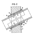
- Fig. 3 is a non-positive and positive connection of a tube with a sleeve arrangement acting as a wear protection element as a floating bearing (guide point with play) in a support plate and
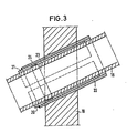
- Fig. 4 is a non-positive and positive connection of a tube with a sleeve arrangement acting as a wear protection element with a fixed point.
- the tube holder consists of a stationary tube holder designed as a support plate 1 as a floating bearing with an opening 2 through which a tube 3 is passed.
- the opening 2 in the support plate 1 is larger than the outer diameter of the tube 3.
- a wear protection element consisting of two shell parts 4 and 5 is arranged.
- the parts 4 and 5 are welded to the support plate 1 and enclose the tube 3 almost completely at a short distance.
- an annular build-up weld 6 which is particularly characterized by its easy testability.
- This ring-shaped build-up welding 6, which can be produced in a simple manner with the aid of a mechanized orbital welding device, and by the connection welding of the shell parts 4 and 5 to the support plate 1 results in a non-positive holding of the tube 3 in the support plate 1 achieved, which also high thermal loads, d. H. Withstands temperatures well above 700 ° C.
- the connection of the shell parts 4 and 5 with the support plate 1 can take place by means of a form-fitting fit and / or by annular section welds 7.
- a particular advantage of this storage of the tube 3 in the shell parts 4 and 5 and the support plate 1 by the annular build-up weld 6 between the shell parts 4, 5 and the tube 3 is that the build-up welding as a wearing part all loads caused by temperature effects, in particular also from very high temperatures, caused or occur, recorded and kept away from the pipe wall or compensated for by the permissible axial play and compensated so that there is certainly no undue stress or frictional stress on the pipe wall by the bracket at these points comes in the support plate 1.
- the two-part half-shell design of the wear protection element also contributes very advantageously to the tension compensation in the region of the holder of the tube 3 of the support plate 1.
- the wear protection element which is arranged between a tube 8 and a support plate 9, also consists of two shell-shaped parts 10 and 11.
- these shell-shaped parts 10 and 11 have on the inside extending in the circumferential direction of the tube 8 Ribs 12 and 13, which rest on the outer wall of the tube 8.
- the form-fitting connection of the tube 8 to the support plate 9 via the half-shell parts 10 and 11 serves as a fixed point and is likewise carried out very advantageously by means of a ring-shaped deposition weld 14 resting on the ribs 12 and 13 and on the inside of the shell parts, and connecting section welding 15, 16.
- the arrangement of the ribs 12, 13 on the inside of the shell parts 10 and 11 creates a larger contact surface for the tube 8, which contributes to a particularly stable fixed-point mounting of the tube 8, without the positive connection of the tube 8 to the shell parts 10 To affect 11. An axial movement play for the tube 8 in the support plate 9 is prevented.
- the wear protection element which is arranged between the tube 3 or 8 can also consist of more than two shell parts.
- a plurality of pipes, preferably running parallel to one another, can also be fastened in a pipe holder with openings corresponding to the number of pipes.
- This consists of an inner one-piece slotted or multi-part conical wedge sleeve 20, 21 and an outer conical clamping bush 22, which are non-positively fixed by wedging on the tube by wedging.
- the non-positive fixation is additionally secured by a form-fitting fastening in that the inner wedge sleeve 20, 21 has on the inside a recess or groove 23 running in the circumferential direction of the tube 18, which rests on the application weld 24 welded annularly on the outer wall of the tube.
- Parts 20 and 21 the inner wedge sleeve are secured after the construction of the pipe holder with the clamping bush 22 at one end by a section weld, as shown on the left in FIGS. 3 and 4.
- the positive fastening of the sleeve arrangement acting as a wearing part by means of a tubular annular build-up weld advantageously enables the use and fixation of similar sleeve arrangements acting as a wear protection element, both at lower operating temperatures (up to 700 ° C only non-positively, without build-up welding), as well as at high operating temperatures ( above 700 ° C by means of positive build-up welding). All loads that occur in the pipe holder, in particular friction stresses due to the permissible axial play of the floating bearing holder, are initially absorbed by the sleeve arrangement as a wearing part and therefore cannot act directly on the pipe wall.
- connection of the tube to the support plate via the sleeve arrangement can be provided with an additional section welding 25.
- the build-up welding can be revised before the parts of the wear protection element are applied to the pipe.
Landscapes
- Engineering & Computer Science (AREA)
- Physics & Mathematics (AREA)
- Thermal Sciences (AREA)
- Mechanical Engineering (AREA)
- General Engineering & Computer Science (AREA)
- Supports For Pipes And Cables (AREA)
- Butt Welding And Welding Of Specific Article (AREA)
- Heat-Exchange Devices With Radiators And Conduit Assemblies (AREA)
- Branch Pipes, Bends, And The Like (AREA)
Claims (6)
Priority Applications (1)
| Application Number | Priority Date | Filing Date | Title |
|---|---|---|---|
| AT85114278T ATE28931T1 (de) | 1984-12-22 | 1985-11-08 | Rohrhalterung in einer oeffnung einer platte. |
Applications Claiming Priority (2)
| Application Number | Priority Date | Filing Date | Title |
|---|---|---|---|
| DE3447264A DE3447264C2 (de) | 1984-12-22 | 1984-12-22 | Rohrhalterung in einer Öffnung einer Platte |
| DE3447264 | 1984-12-22 |
Publications (2)
| Publication Number | Publication Date |
|---|---|
| EP0185902A1 EP0185902A1 (fr) | 1986-07-02 |
| EP0185902B1 true EP0185902B1 (fr) | 1987-08-12 |
Family
ID=6253795
Family Applications (1)
| Application Number | Title | Priority Date | Filing Date |
|---|---|---|---|
| EP85114278A Expired EP0185902B1 (fr) | 1984-12-22 | 1985-11-08 | Support de tube dans l'ouverture d'une plaque |
Country Status (4)
| Country | Link |
|---|---|
| US (1) | US4674567A (fr) |
| EP (1) | EP0185902B1 (fr) |
| AT (1) | ATE28931T1 (fr) |
| DE (2) | DE3447264C2 (fr) |
Families Citing this family (6)
| Publication number | Priority date | Publication date | Assignee | Title |
|---|---|---|---|---|
| DE3731987A1 (de) * | 1987-09-23 | 1989-04-06 | Steinmueller Gmbh L & C | Rohrhalterung |
| ATA137288A (de) * | 1988-05-25 | 1997-12-15 | Roth Technik Austria | Bauteil, insbesondere abgaskrümmer für brennkraftmaschinen sowie verfahren zur herstellung desselben |
| US7431074B1 (en) * | 2006-03-20 | 2008-10-07 | Fellman Michael L | Radiator structure |
| DE102011051866A1 (de) | 2011-07-15 | 2013-01-17 | Contitech Techno-Chemie Gmbh | Lötlose Befestigung einer Rohrleitung |
| CN106764092B (zh) * | 2017-01-20 | 2019-05-03 | 合肥志功机电工程有限公司 | 母线穿墙密封结构 |
| CN113983241A (zh) * | 2021-11-10 | 2022-01-28 | 上海外高桥造船有限公司 | 采用结构护圈加强管子的安装方法及加强管子组件 |
Citations (2)
| Publication number | Priority date | Publication date | Assignee | Title |
|---|---|---|---|---|
| DE1601243B2 (de) * | 1968-01-23 | 1971-11-18 | Gebrüder Sulzer AG, Winterthur (Schweiz) | Wärmeübertrager mit in einer Stützplatte geführten Rohre |
| DE3001756A1 (de) * | 1979-01-19 | 1980-07-24 | Sterling Drug Inc | Korrosionsfeste verbindungsanordnung |
Family Cites Families (10)
| Publication number | Priority date | Publication date | Assignee | Title |
|---|---|---|---|---|
| US2013660A (en) * | 1933-11-18 | 1935-09-10 | Thomas W Barnhill | Key connecter |
| US2056920A (en) * | 1935-07-17 | 1936-10-06 | Gen Motors Corp | Heat exchanger for refrigerating systems |
| US2252069A (en) * | 1939-08-01 | 1941-08-12 | Babcock & Wilcox Co | Heat exchanger |
| US2528180A (en) * | 1946-03-02 | 1950-10-31 | William J Roehl | Pipe clamp |
| US3438655A (en) * | 1967-09-27 | 1969-04-15 | L & L Mfg Co | Fluid pressure coupling |
| CH558514A (de) * | 1972-11-28 | 1975-01-31 | Sulzer Ag | Vorrichtung zum durchfuehren eines rohrbuendels durch eine behaelterwand. |
| US4192374A (en) * | 1977-02-04 | 1980-03-11 | United Kingdom Atomic Energy Authority | Heat exchangers |
| CH625324A5 (fr) * | 1977-09-13 | 1981-09-15 | Sulzer Ag | |
| LU78118A1 (fr) * | 1977-09-13 | 1979-05-23 | Denis J | Echangeur de chaleur |
| US4305453A (en) * | 1979-11-19 | 1981-12-15 | Rockwell International Corporation | Slide guide for tube-type heat exchanger |
-
1984
- 1984-12-22 DE DE3447264A patent/DE3447264C2/de not_active Expired
-
1985
- 1985-11-08 AT AT85114278T patent/ATE28931T1/de not_active IP Right Cessation
- 1985-11-08 DE DE8585114278T patent/DE3560468D1/de not_active Expired
- 1985-11-08 EP EP85114278A patent/EP0185902B1/fr not_active Expired
- 1985-12-20 US US06/811,498 patent/US4674567A/en not_active Expired - Fee Related
Patent Citations (2)
| Publication number | Priority date | Publication date | Assignee | Title |
|---|---|---|---|---|
| DE1601243B2 (de) * | 1968-01-23 | 1971-11-18 | Gebrüder Sulzer AG, Winterthur (Schweiz) | Wärmeübertrager mit in einer Stützplatte geführten Rohre |
| DE3001756A1 (de) * | 1979-01-19 | 1980-07-24 | Sterling Drug Inc | Korrosionsfeste verbindungsanordnung |
Also Published As
| Publication number | Publication date |
|---|---|
| EP0185902A1 (fr) | 1986-07-02 |
| US4674567A (en) | 1987-06-23 |
| DE3560468D1 (en) | 1987-09-17 |
| DE3447264C2 (de) | 1986-11-06 |
| DE3447264A1 (de) | 1986-07-03 |
| ATE28931T1 (de) | 1987-08-15 |
Similar Documents
| Publication | Publication Date | Title |
|---|---|---|
| DE102008031910B4 (de) | Vorrichtung zur Halterung eines Lagersystems | |
| DE3882299T2 (de) | Verfahren zum Reparieren von Turbinenschaufeln. | |
| DE10031427C2 (de) | Käfig für ein Wälzlager | |
| DE2716385C3 (de) | Bohrlochkopf | |
| DE19625318A1 (de) | Konusschraubverbindung für Lamellenpaket-Wellenkupplungen | |
| EP0185902B1 (fr) | Support de tube dans l'ouverture d'une plaque | |
| CH662621A5 (de) | Wellenkupplung. | |
| EP2492517A1 (fr) | Agencement de liaison pour tuyaux en bambou | |
| DE4028237C2 (fr) | ||
| EP3500786A1 (fr) | Griffe de fixation | |
| DE2558816C3 (de) | Reaktor für die Nachverbrennung der Abgase einer Brennkraftmaschine | |
| EP0035071A1 (fr) | Raccord de tuyaux flexible et isolé électriquement | |
| DE2728399A1 (de) | Brennkammer fuer eine gasturbine | |
| DE10222559B4 (de) | Rohrkompensatoranordnung zur Aufnahme von bei Erwärmung oder Abkühlung eines Leitungsrohrs auftretenden axialen und lateralen Bewegungen | |
| DE20119640U1 (de) | Radlagerung an einem Achskörper für Fahrzeuge | |
| DE102011100334A1 (de) | Verbindungsanordnung für Bambusrohre | |
| DE19953379A1 (de) | Reibkonus für eine Spannvorrichtung | |
| DE10004178A1 (de) | Bolzenführungseinrichtung für eine Schwimmsattel-Scheibenbremse | |
| DE102007019699A1 (de) | Schraubverbindung | |
| DE102016117083A1 (de) | Federanordnung zur Erzeugung der Einzugskraft einer Spannvorrichtung und Spannvorrichtung mit einer derartigen Federanordnung | |
| DE19858295C1 (de) | Starre Rohrverbindung für Abgasrohre von Brennkraftmaschinen | |
| DE1426870B2 (de) | Leitschaufelbefestigung fuer eine gasturbine | |
| DE3830241C2 (fr) | ||
| CH627223A5 (en) | Door-handle connection | |
| EP0921342A2 (fr) | Raccord de tuyaux |
Legal Events
| Date | Code | Title | Description |
|---|---|---|---|
| PUAI | Public reference made under article 153(3) epc to a published international application that has entered the european phase |
Free format text: ORIGINAL CODE: 0009012 |
|
| AK | Designated contracting states |
Kind code of ref document: A1 Designated state(s): AT BE CH DE FR GB IT LI LU NL SE |
|
| 17P | Request for examination filed |
Effective date: 19860819 |
|
| 17Q | First examination report despatched |
Effective date: 19861128 |
|
| GRAA | (expected) grant |
Free format text: ORIGINAL CODE: 0009210 |
|
| AK | Designated contracting states |
Kind code of ref document: B1 Designated state(s): AT BE CH DE FR GB IT LI LU NL SE |
|
| PG25 | Lapsed in a contracting state [announced via postgrant information from national office to epo] |
Ref country code: IT Free format text: LAPSE BECAUSE OF FAILURE TO SUBMIT A TRANSLATION OF THE DESCRIPTION OR TO PAY THE FEE WITHIN THE PRESCRIBED TIME-LIMIT;WARNING: LAPSES OF ITALIAN PATENTS WITH EFFECTIVE DATE BEFORE 2007 MAY HAVE OCCURRED AT ANY TIME BEFORE 2007. THE CORRECT EFFECTIVE DATE MAY BE DIFFERENT FROM THE ONE RECORDED. Effective date: 19870812 Ref country code: FR Free format text: THE PATENT HAS BEEN ANNULLED BY A DECISION OF A NATIONAL AUTHORITY Effective date: 19870812 Ref country code: BE Effective date: 19870812 |
|
| REF | Corresponds to: |
Ref document number: 28931 Country of ref document: AT Date of ref document: 19870815 Kind code of ref document: T |
|
| PG25 | Lapsed in a contracting state [announced via postgrant information from national office to epo] |
Ref country code: SE Effective date: 19870831 |
|
| REF | Corresponds to: |
Ref document number: 3560468 Country of ref document: DE Date of ref document: 19870917 |
|
| PG25 | Lapsed in a contracting state [announced via postgrant information from national office to epo] |
Ref country code: AT Effective date: 19871108 |
|
| PG25 | Lapsed in a contracting state [announced via postgrant information from national office to epo] |
Ref country code: LU Free format text: LAPSE BECAUSE OF NON-PAYMENT OF DUE FEES Effective date: 19871130 |
|
| PGFP | Annual fee paid to national office [announced via postgrant information from national office to epo] |
Ref country code: NL Payment date: 19871130 Year of fee payment: 3 |
|
| EN | Fr: translation not filed | ||
| PLBE | No opposition filed within time limit |
Free format text: ORIGINAL CODE: 0009261 |
|
| STAA | Information on the status of an ep patent application or granted ep patent |
Free format text: STATUS: NO OPPOSITION FILED WITHIN TIME LIMIT |
|
| 26N | No opposition filed | ||
| PG25 | Lapsed in a contracting state [announced via postgrant information from national office to epo] |
Ref country code: NL Effective date: 19900601 |
|
| NLV4 | Nl: lapsed or anulled due to non-payment of the annual fee | ||
| PGFP | Annual fee paid to national office [announced via postgrant information from national office to epo] |
Ref country code: CH Payment date: 19901119 Year of fee payment: 6 |
|
| PGFP | Annual fee paid to national office [announced via postgrant information from national office to epo] |
Ref country code: GB Payment date: 19910102 Year of fee payment: 6 |
|
| PGFP | Annual fee paid to national office [announced via postgrant information from national office to epo] |
Ref country code: DE Payment date: 19910115 Year of fee payment: 6 |
|
| PG25 | Lapsed in a contracting state [announced via postgrant information from national office to epo] |
Ref country code: GB Effective date: 19911108 |
|
| PG25 | Lapsed in a contracting state [announced via postgrant information from national office to epo] |
Ref country code: LI Effective date: 19911130 Ref country code: CH Effective date: 19911130 |
|
| GBPC | Gb: european patent ceased through non-payment of renewal fee | ||
| REG | Reference to a national code |
Ref country code: CH Ref legal event code: PL |
|
| PG25 | Lapsed in a contracting state [announced via postgrant information from national office to epo] |
Ref country code: DE Effective date: 19920801 |