EP0185940A2 - Réservoir de chasse d'eau pour toilettes - Google Patents
Réservoir de chasse d'eau pour toilettes Download PDFInfo
- Publication number
- EP0185940A2 EP0185940A2 EP85114852A EP85114852A EP0185940A2 EP 0185940 A2 EP0185940 A2 EP 0185940A2 EP 85114852 A EP85114852 A EP 85114852A EP 85114852 A EP85114852 A EP 85114852A EP 0185940 A2 EP0185940 A2 EP 0185940A2
- Authority
- EP
- European Patent Office
- Prior art keywords
- lever
- additional weight
- valve body
- spring
- emptying
- Prior art date
- Legal status (The legal status is an assumption and is not a legal conclusion. Google has not performed a legal analysis and makes no representation as to the accuracy of the status listed.)
- Withdrawn
Links
Images


Classifications
-
- E—FIXED CONSTRUCTIONS
- E03—WATER SUPPLY; SEWERAGE
- E03D—WATER-CLOSETS OR URINALS WITH FLUSHING DEVICES; FLUSHING VALVES THEREFOR
- E03D1/00—Water flushing devices with cisterns ; Setting up a range of flushing devices or water-closets; Combinations of several flushing devices
- E03D1/02—High-level flushing systems
- E03D1/14—Cisterns discharging variable quantities of water also cisterns with bell siphons in combination with flushing valves
- E03D1/142—Cisterns discharging variable quantities of water also cisterns with bell siphons in combination with flushing valves in cisterns with flushing valves
- E03D1/144—Cisterns discharging variable quantities of water also cisterns with bell siphons in combination with flushing valves in cisterns with flushing valves having a single flush outlet and an additional float for delaying the valve closure
Definitions
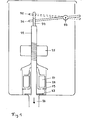
- a sealing ring 23 is attached below on a pipe 22, which also serves as an overflow pipe.
- a floating body 25 is attached to the tube at a medium height.
- the tube 22 can be raised by actuating the lever 35, which engages in the bracket 34 and is rotatable about the axis 37. If this happens, the sealing ring 23 is simultaneously raised against the hydrostatic pressure.
- the drain 24 then remains open until the level has dropped to the level of the float 25.
- the valve then closes due to its own weight and the effect of an additional weight connected to the tube 22, which together with the former somewhat outweighs the buoyancy of the floating body 27.
- the former is shown in broken lines in FIG. 1, in the position which it assumes after the right end has been depressed.
- the object of the present invention is to improve the construction just described while maintaining the compact structure so that the function of the magnetic coupling is replaced by a purely mechanical control mechanism. This can be achieved according to the invention if the additional weight is not connected to the tube 22, but rather is integrated into the lever mechanism 35, 36 in such a way that it only becomes effective when the lever 35 is actuated. In the following, seven design suggestions are made by which this task is solved.
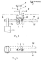
- the first proposal consists in arranging the additional weight in such a way that when the lever 36 is actuated it engages on a support element which is fixedly connected to the cistern, but is released again when the lever 35 is actuated.
- FIGS. 2 and 3 show a detail of Fig. 2 from the perspective of arrows III - III.
- the plate 1 is shaped so that it has a neck 4 through which Slot is guided in the support member 5.
- the additional weight 33 is attached to it.
- the support element can be designed as a crossbar in the cistern.
- the plate 1 tilts to the left and remains in the downward movement after releasing the lever with the nose 6 on the support element.
- the weight 33 then no longer bears on the valve body 22, so that the valve remains open until the cistern is emptied.
- the levers 35 and 36 engage in the bracket 34 in two elongated holes, which allow sufficient vertical play.
- the lever 36 is actuated again, the plate remains in its position, so that emptying takes place analogously.
- the additional weight is connected directly to the lever 36 and its function is controlled according to claim 3 by the movement of the valve body.
- An exemplary embodiment of this is described with reference to FIG. 4.
- the lever 36 which can be designed for this purpose as a fork, that is rotatable about the axis 10 T-shaped element 11 attached. Its movement is so limited by the stops 12 that it can only tip back and forth. The left end of the T-piece engages in the bracket 34, but this time the vertical play is limited. If the lever 36 is raised, the T-piece tilts to the left due to the resistance of the valve body. Since the valve remains in the upper position after opening due to the buoyancy of the floating bodies, the T-piece tilts to the right after release due to the then downward movement of the lever 36, the upper end of the cross-piece hooking onto the cross-rod 13.
- the T-piece which now bears on the bracket 34 with the lever 36, remains in the position tilted to the right and is therefore not hooked on.
- the hook 14 does not abut the crossbar 13, so that the stroke of the valve body is not reduced. Since during this actuation, as already mentioned, the lever 36 with the additional weight 33 always bears on the valve body during the emptying, the valve closes prematurely in the manner described above.
- the additional weight can be dispensed with if the T-piece is made of a sufficiently heavy material, e.g. B. brass is made.
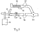
- FIG. 5 in turn shows a T-piece 11, which is fastened to the lever 36 as in FIG. 4 and can perform the tilting movement limited by the stops 12. However, the hook at the top of the T-piece is missing.
- the additional weight 33 is fastened to a lever 15 which can be rotated about the same axis 37 as the lever 36 (see FIG. 1) and, in the rest position of the lever 36, rests on the support element 13 which is firmly connected to the cistern. If the lever 36 is actuated, the T-piece tilts to the left, so that its upper end moves past the left end of the lever 15 and only returns to the starting position after the valve has been closed. In this type of actuation, the additional weight 33 therefore does not bear on the valve body during emptying.
- valve body is raised by the lever 35, which is not shown here, as arranged in FIG. 1, the T-piece remains tilted to the right, so that its upper end also lifts the additional weight 33. This therefore loads the valve body during emptying and ends it prematurely.
- an L-shaped actuator can be attached to the lever 35, the rotational movement of which, like that of the T-piece, is limited by stops and which is tilted by a bolt attached to the lever 36. Since in this arrangement the lever 35 can be lifted by the lever 36, only the lever 35 needs to engage in the bracket 34 so that the lever 36 can be shortened.
- An exemplary embodiment of this is sketched in FIGS. 6 and 6a.
- the nose 19 is attached on the left and the crossbar 20 on the right.
- the axis 37 is fastened on both sides or on a (preferably the rear) side of the lever by means of an elongated hole 39 on the support element 38 so that the lever 36 in addition to the rotational movement in the plane of the drawing of FIG Can run longitudinal axis.
- the hole in the bracket 34 into which the lever engages serves as the second fulcrum for this tilting movement.
- the lever 15 is also fastened to the support element 38 with the aid of the axis 40, as shown in FIG. 7a, and on this the additional weight 33. The lever 15 rests on the stop 13 in the rest position.
- the nose 19 tilts forward and then moves upwards in front of the lever 15 when the rod 20 is further depressed.
- the additional weight 33 is thus not raised in this case, so that it is completely emptied.
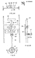
- FIG. 8 shows the cistern outlined in FIG. 1 from above.
- the figures 8A to 8D show details from FIG. 8 from the perspective of the correspondingly designated arrows A - A to D - D.
- the axis 41 rigidly connected to the lever 36 is rotatably mounted on the bridge 38 with the aid of the clamp 39.
- the extensions of the axis 41 on both sides serve to limit the tilting movement of the lever 36 about its longitudinal axis and at the same time absorb the torsional forces which occur when the ends of the crossbar 20 are pressed down so that no additional frictional forces act on the clamp 39.
- the supports 42 serve as stops for the tilting movement about the longitudinal axis.
- the axis 41 is bent, as shown in FIG. 8a, so that the part of the axis effective in the respective tilting position runs horizontally.
- the notch 50 prevents the axle from slipping to the side.
- the lever 36 If one of the ends of the transverse rod 20 is depressed, the lever 36 first assumes one of the possible tilt positions with respect to its longitudinal axis and then rotates about the transverse axis 41. In the process, it presses against the spring 43, which is guided through the mandrel 44. The mandrel 44 is attached to the extension 48 of the bridge 38 and engages in the hole 45 in the lever 36. A deflection of the spring upwards is prevented by the stop 47, which has the shape of a clip and enables the spring to be easily installed. The length of the spring is dimensioned such that it is only compressed when the valve body which opens when the lever 36 is rotated is raised by a distance which corresponds to approximately 1/2 to 2/3 of the total stroke.
- FIGS. 8 C and 8 D show, designed in such a way that it has different effects depending on the tilt position which the lever 36 assumes with respect to its longitudinal axis.
- lever 36 If the lever 36 is in the position shown in FIG. 4C, its end, which has an L-shaped cross section, can slide up and down in the bracket 34, which has the following purpose. If the valve body is raised in this position of the lever 36, it can move freely upwards under the effect of the buoyancy of the two floats, the lower part of the L-shaped cross section of the lever sliding into the slot 46. If the lever 36 abuts the spring 43 during this type of actuation, the spring relaxes again immediately after the lever is released, thanks to a sufficient dimensioning of the opening in the bracket 34, and does not act on the valve body. The cistern therefore empties completely in a known manner with this type of actuation. In the rest position, the lever 36 is prevented from sinking into the slot 46 by the extension 48 serving as a stop.
- the lever 1 36 can be brought from the rest position into the position shown in FIG. 4 D by corresponding actuation of the cross bar 20. If the valve body is raised in this position of the lever, the lower end of the L-shaped cross section hooks onto the projection 49, so that the spring 43 is tensioned during the opening process by the buoyancy of the two floats. In this case, since the force effect is such that, together with the weight of the valve body, it slightly outweighs the buoyancy of the lower float 27, the valve closes when the water level reaches the position of the upper float 25.
- buttons which are integrated in the lid of the cistern and arranged parallel to the cistern, to each of which a nose is attached.
- the points of action of these lugs on the crossbar 20 are to be placed as close as possible to the lever 36 in order to avoid long distances when carrying out the longitudinal tilting.
- the T-shaped element 16 is rotatably attached to the lever 36 and can perform a tilting movement limited by the stops 17. In the rest position, the T-piece 16 is in the position tilted to the right due to an excess weight of the right arm.
- the lever 36 is actuated, the lever 15 with the additional weight 33, which rests on the stop 13 in the rest position, is also lifted. If the lever 36 is only raised until the left arm of the T-piece 16 abuts the stop 18, the weight 33 is additionally loaded on the valve body 22 during emptying, so that the valve closes prematurely. However, if Lever 36 further raised when opening, the T-piece is tilted to the left, so that the lever 15 is released and falls back on the stop 13. The additional weight 33 no longer bears on the valve body during the emptying, which results in full emptying.
- an elongated hole is provided in the bracket 34, in which the lever 36 has sufficient play.
- the resistance at the first pressure point can be realized in that the left end of the lever 15 is bent slightly downward, so that the upper end of the element 16 hooks in easily.
- the stated principle can also be changed in such a way that the release of the additional weight is caused by a horizontal movement of the actuating lever, which takes place either simultaneously with or after the vertical movement.
Landscapes
- Health & Medical Sciences (AREA)
- Life Sciences & Earth Sciences (AREA)
- Engineering & Computer Science (AREA)
- Hydrology & Water Resources (AREA)
- Public Health (AREA)
- Water Supply & Treatment (AREA)
- Vehicle Waterproofing, Decoration, And Sanitation Devices (AREA)
- Float Valves (AREA)
Applications Claiming Priority (6)
| Application Number | Priority Date | Filing Date | Title |
|---|---|---|---|
| DE8434369U | 1984-11-23 | ||
| DE19848434369 DE8434369U1 (de) | 1984-11-23 | 1984-11-23 | WC - Spülkasten |
| DE19858502680 DE8502680U1 (de) | 1985-02-01 | 1985-02-01 | WC - Spülkasten |
| DE8502680U | 1985-02-01 | ||
| DE19858502988 DE8502988U1 (de) | 1985-02-04 | 1985-02-04 | WC - Spülkasten |
| DE8502988U | 1985-02-04 |
Publications (2)
| Publication Number | Publication Date |
|---|---|
| EP0185940A2 true EP0185940A2 (fr) | 1986-07-02 |
| EP0185940A3 EP0185940A3 (fr) | 1987-08-26 |
Family
ID=27207618
Family Applications (1)
| Application Number | Title | Priority Date | Filing Date |
|---|---|---|---|
| EP85114852A Withdrawn EP0185940A3 (fr) | 1984-11-23 | 1985-11-22 | Réservoir de chasse d'eau pour toilettes |
Country Status (1)
| Country | Link |
|---|---|
| EP (1) | EP0185940A3 (fr) |
Cited By (4)
| Publication number | Priority date | Publication date | Assignee | Title |
|---|---|---|---|---|
| AU569953B2 (en) * | 1984-07-12 | 1988-02-25 | Richelle Pty. Ltd. | Cistern with weight-biased outlet valve |
| NL9201516A (nl) * | 1992-08-28 | 1994-03-16 | Wisa Bv | Spoelonderbrekingsmechanisme. |
| WO2011018712A3 (fr) * | 2009-08-13 | 2011-05-19 | Ecobeta A/S | Système de robinetterie pour toilettes à double chasse |
| EP3900530A1 (fr) | 2020-04-23 | 2021-10-27 | Bayer AG | Gestion du liquide pour un dispositif d'arrêt |
Family Cites Families (8)
| Publication number | Priority date | Publication date | Assignee | Title |
|---|---|---|---|---|
| US3987501A (en) * | 1974-06-17 | 1976-10-26 | Producers Specialty & Mfg. Co., Inc. | Toilet flush assembly |
| DE2601282A1 (de) * | 1976-01-15 | 1977-07-21 | Wilhelm Zecher | Vorrichtung zum entleeren und selbsttaetigen fuellen eines wasserspeichers, insbesondere toilettenspuelkasten |
| DE2629126C2 (de) * | 1976-06-29 | 1982-04-15 | Hermann 6271 Hünstetten Brahm | Vorrichtung zur Begrenzung des Wasserauslaufes aus Wasserbehältern, insbesondere aus Spülkästen für Toiletten |
| GB2077790A (en) * | 1980-04-30 | 1981-12-23 | Ten Sung Chang | Dual flush water closet cisterns |
| AU3100684A (en) * | 1983-06-14 | 1985-01-11 | Altmann Konrad | Wc-spulkasten |
| DE8502988U1 (de) * | 1985-02-04 | 1985-07-18 | Altmann, Konrad, Dipl.-Phys. Dr., 8000 München | WC - Spülkasten |
| DE8434369U1 (de) * | 1984-11-23 | 1985-07-18 | Altmann, Konrad, Dipl.-Phys. Dr., 8000 München | WC - Spülkasten |
| DE8502680U1 (de) * | 1985-02-01 | 1985-07-18 | Altmann, Konrad, Dipl.-Phys. Dr., 8000 München | WC - Spülkasten |
-
1985
- 1985-11-22 EP EP85114852A patent/EP0185940A3/fr not_active Withdrawn
Cited By (5)
| Publication number | Priority date | Publication date | Assignee | Title |
|---|---|---|---|---|
| AU569953B2 (en) * | 1984-07-12 | 1988-02-25 | Richelle Pty. Ltd. | Cistern with weight-biased outlet valve |
| NL9201516A (nl) * | 1992-08-28 | 1994-03-16 | Wisa Bv | Spoelonderbrekingsmechanisme. |
| WO2011018712A3 (fr) * | 2009-08-13 | 2011-05-19 | Ecobeta A/S | Système de robinetterie pour toilettes à double chasse |
| EP3900530A1 (fr) | 2020-04-23 | 2021-10-27 | Bayer AG | Gestion du liquide pour un dispositif d'arrêt |
| WO2021213824A1 (fr) | 2020-04-23 | 2021-10-28 | Bayer Aktiengesellschaft | Gestion de fluide pour un dispositif de piégeage |
Also Published As
| Publication number | Publication date |
|---|---|
| EP0185940A3 (fr) | 1987-08-26 |
Similar Documents
| Publication | Publication Date | Title |
|---|---|---|
| DE3786751T2 (de) | Zweimengen-Spülkastenmechanismus. | |
| CH651341A5 (de) | Betaetigungsvorrichtung fuer das ablaufventil eines unterputz-spuelkastens. | |
| EP0185940A2 (fr) | Réservoir de chasse d'eau pour toilettes | |
| DE9215972U1 (de) | Spülkasten-Ablaufventil | |
| CH653560A5 (de) | Mit einer skibremse kombinierter fersenhalter. | |
| CH662858A5 (de) | Saeule mit daran befestigten vorrichtungen. | |
| DE60022844T2 (de) | Automatische Snowboardbindung | |
| AT391276B (de) | Sicherheits-skibindung | |
| DE3541369A1 (de) | Wc-spuelkasten | |
| DE2905893C2 (de) | Bremsvorrichtung für fahrbare Behälter | |
| EP1010826B1 (fr) | Dispositif d'écoulement pour chasse d'eau | |
| WO2014124788A1 (fr) | Mécanisme de chasse d'eau | |
| DE2611604C2 (de) | Vorrichtung zur Begrenzung des Wasserauslaufes aus Wasserbehältern mit einem Bodenauslauf | |
| DE8434369U1 (de) | WC - Spülkasten | |
| DE1780488B2 (de) | Vorrichtung zur verstellung der lage einer sattelkupplung auf einer sattelzugmaschine | |
| EP1270829B1 (fr) | Dispositif pour l'actionnement d'une soupape de vidange d'un réservoir de chasse d'eau | |
| EP0103046A1 (fr) | Soupape d'évacuation d'un réservoir de chasse | |
| EP1580338B1 (fr) | Clapet de vidange pour un réservoir de chasse d'eau | |
| DE956980C (de) | Greiferzangenschloss fuer Aufzuege | |
| EP0537112A1 (fr) | Dispositif pour l'actionnement d'une soupape de vidange d'un réservoir de chasse d'eau | |
| DE4126600C2 (de) | Transportgreifer mit Sperreinrichtung | |
| WO1989002409A1 (fr) | Fixation de pelle pour chariot elevateur a fourche | |
| EP1195475A2 (fr) | Dispositif de chasse pour chasse d'eau de WC | |
| EP1208272A1 (fr) | Dispositif d'actionnement pour armature d'ecoulement d'un reservoir de chasse | |
| DE1474752C3 (de) | Schachtautomat |
Legal Events
| Date | Code | Title | Description |
|---|---|---|---|
| PUAI | Public reference made under article 153(3) epc to a published international application that has entered the european phase |
Free format text: ORIGINAL CODE: 0009012 |
|
| AK | Designated contracting states |
Kind code of ref document: A2 Designated state(s): CH DE FR LI NL |
|
| PUAL | Search report despatched |
Free format text: ORIGINAL CODE: 0009013 |
|
| AK | Designated contracting states |
Kind code of ref document: A3 Designated state(s): CH DE FR LI NL |
|
| STAA | Information on the status of an ep patent application or granted ep patent |
Free format text: STATUS: THE APPLICATION IS DEEMED TO BE WITHDRAWN |
|
| 18D | Application deemed to be withdrawn |
Effective date: 19880227 |