EP0186005B1 - Brosse-suceur d'aspiration pourvue de roues - Google Patents
Brosse-suceur d'aspiration pourvue de roues Download PDFInfo
- Publication number
- EP0186005B1 EP0186005B1 EP85115520A EP85115520A EP0186005B1 EP 0186005 B1 EP0186005 B1 EP 0186005B1 EP 85115520 A EP85115520 A EP 85115520A EP 85115520 A EP85115520 A EP 85115520A EP 0186005 B1 EP0186005 B1 EP 0186005B1
- Authority
- EP
- European Patent Office
- Prior art keywords
- brush
- suction
- roller
- brush roller
- bristles
- Prior art date
- Legal status (The legal status is an assumption and is not a legal conclusion. Google has not performed a legal analysis and makes no representation as to the accuracy of the status listed.)
- Expired
Links
Images
Classifications
-
- A—HUMAN NECESSITIES
- A47—FURNITURE; DOMESTIC ARTICLES OR APPLIANCES; COFFEE MILLS; SPICE MILLS; SUCTION CLEANERS IN GENERAL
- A47L—DOMESTIC WASHING OR CLEANING; SUCTION CLEANERS IN GENERAL
- A47L9/00—Details or accessories of suction cleaners, e.g. mechanical means for controlling the suction or for effecting pulsating action; Storing devices specially adapted to suction cleaners or parts thereof; Carrying-vehicles specially adapted for suction cleaners
- A47L9/02—Nozzles
- A47L9/04—Nozzles with driven brushes or agitators
- A47L9/0405—Driving means for the brushes or agitators
- A47L9/0416—Driving means for the brushes or agitators driven by fluid pressure, e.g. by means of an air turbine
-
- A—HUMAN NECESSITIES
- A47—FURNITURE; DOMESTIC ARTICLES OR APPLIANCES; COFFEE MILLS; SPICE MILLS; SUCTION CLEANERS IN GENERAL
- A47L—DOMESTIC WASHING OR CLEANING; SUCTION CLEANERS IN GENERAL
- A47L5/00—Structural features of suction cleaners
- A47L5/12—Structural features of suction cleaners with power-driven air-pumps or air-compressors, e.g. driven by motor vehicle engine vacuum
- A47L5/22—Structural features of suction cleaners with power-driven air-pumps or air-compressors, e.g. driven by motor vehicle engine vacuum with rotary fans
- A47L5/28—Suction cleaners with handles and nozzles fixed on the casings, e.g. wheeled suction cleaners with steering handle
- A47L5/34—Suction cleaners with handles and nozzles fixed on the casings, e.g. wheeled suction cleaners with steering handle with height adjustment of nozzles or dust-loosening tools
-
- A—HUMAN NECESSITIES
- A47—FURNITURE; DOMESTIC ARTICLES OR APPLIANCES; COFFEE MILLS; SPICE MILLS; SUCTION CLEANERS IN GENERAL
- A47L—DOMESTIC WASHING OR CLEANING; SUCTION CLEANERS IN GENERAL
- A47L9/00—Details or accessories of suction cleaners, e.g. mechanical means for controlling the suction or for effecting pulsating action; Storing devices specially adapted to suction cleaners or parts thereof; Carrying-vehicles specially adapted for suction cleaners
- A47L9/02—Nozzles
- A47L9/04—Nozzles with driven brushes or agitators
- A47L9/0494—Height adjustment of dust-loosening tools
Definitions
- the invention relates to a brush suction nozzle provided with impellers, which has a height-adjustable, rotatable brush roller which is arranged in a roller chamber in the mouthpiece housing and which, with its bristles in the working position, reaches through a suction slot provided in the base plate of the roller chamber and is driven by a drive unit arranged in the mouthpiece housing.
- Such a brush suction mouthpiece is known from DE-A-2 057 466.
- the use of such mouthpieces is practically only possible on textile floor surfaces.
- the floor slab with the suction slot must be lifted off the floor surface to avoid scratching both the floor covering and the floor slab.
- the base plate is arranged higher than the bearing surface of the impellers.
- the cleaning effect of the mouthpiece on hard floors is considerably impaired, since the flow velocity of the suction air below the base plate decreases considerably as a result of the distance between the base plate.
- the rotating brush roller also interferes. If the drive of the brush roller were stopped, the stationary brush roller partially blocked the suction slot and further reduced the suction power of the mouthpiece. In addition, a large proportion of the dirt that is sucked up settles on the brush roller.
- the invention has for its object to provide a brush suction mouthpiece of the type described in such a way that a good cleaning result can be achieved with such a mouthpiece even on hard floors without the risk of contamination of the brush roller.
- the object is achieved according to the invention in that in the area in which the base plate merges into the mouthpiece housing or is connected to it, an elastic sleeve extending over the full width of the mouthpiece is arranged on each side of the suction slot, wherein both sleeves extend to the support level or just up to the support level of the impellers that the brush roller is adjustable in height so far that its bristles no longer touch the surface to be extracted, and can be locked in this position.
- the sleeves create a largely closed space under the suction slot and the inflow of the suction air is concentrated on the slots existing between the edges of the sleeve and the surface to be extracted.
- the suction air reaches high speeds here and is therefore able to carry more dirt with it.
- the hard floor is no longer touched by the raised brush roller, so that the dirt is no longer thrown away from the brush roller. Wear of the brush roller is also avoided.
- Dirt pick-up in the immediate vicinity of the walls delimiting the floor to be suctioned off is achieved in that a continuous front suction slot or several front suction openings are provided in the base plate immediately after the front sleeve.
- a braking device which brakes the rotation of the brush roller in its uppermost position is arranged in the roller chamber.
- a particularly simple construction of the braking device consists of a bar arranged in the roller chamber, on which the brush roller brushes with its bristles in its uppermost position. The brush roller is braked in the same way as when brushing the bristles over the floor surface to be cleaned.
- a reduction in the sliding resistance is achieved in that at least the sleeve arranged on the front side wall of the roller chamber is fastened to the side wall only in the region of its upper edge and lies loosely against the side wall in the region from the fastening point to the end of the side wall.
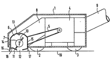
- the brush roller 7 is, as indicated by an arrow 10, arranged in the roller chamber 6 to be adjustable in height.
- the adjustment mechanism required for this is not shown in the drawing.
- the height adjustment can be carried out, for example, by means of a pivotally mounted rocker arm, with one end of which the axis of rotation of the brush roller is connected and the other end of which is coupled to an operating element which is adjustable from outside the housing.
- the brush roller 7 in the roller chamber 6 can be adjusted upwards to such an extent that its bristles no longer come out of that in the base plate 11 Step out of the roller chamber 6 provided suction slot 12.
- a bar 13 is arranged which is dimensioned such that the brush roller 7 brushes the bar 13 in its upper position with its bristles. The brush roller 7 can be locked in the upper position.
- the cuffs 16 and 17 can be designed as a one-piece strip made of rubber, plastic, non-woven material or the like, but also as a tight brush strip.
- the cuff 16 arranged on the front side wall 14 of the roller chamber 6 is fastened to the side wall 14 relatively high up. In the lower area, the cuff 16 lies only on the side wall 14.
- a front suction slot 18 is provided in the base plate 11 of the roller chamber 6 immediately after the front side wall 14. Instead of such a front suction slot 18, a plurality of front suction openings arranged in a row can also be provided.
- the front suction slot 18 results in a stronger suction air flow directly behind the sleeve 16 fastened to the front side wall 14, through which the dirt is absorbed in the front area of the base plate 11. This achieves a good cleaning effect right up to the boundary walls of the surface to be extracted.
- the brush roller 7 can be brought into its upper position when vacuuming on hard floor, so that its bristles no longer touch the floor and can thus throw away the dirt stored on the floor. If the brush roller 7 is driven by a turbine actuated by the suction air, then it is advantageous that its rotational movement is braked in the upper position in order to avoid an increase in the speed of the practically idling turbine associated with a corresponding noise development.
- the strip 13 is provided on the ceiling of the roller chamber 6, on which the brush roller 7 brushes with its bristles and is thereby braked as when the carpet pile is slipped on. By lifting the brush roller 7, the suction slot 12 is released so that the suction air can flow through unhindered. The fact that the brush roller 7 continues to rotate in the upper position prevents dirt from being deposited thereon.
Landscapes
- Engineering & Computer Science (AREA)
- Mechanical Engineering (AREA)
- Nozzles For Electric Vacuum Cleaners (AREA)
Claims (5)
Applications Claiming Priority (2)
| Application Number | Priority Date | Filing Date | Title |
|---|---|---|---|
| DE8437619U DE8437619U1 (de) | 1984-12-21 | 1984-12-21 | Mit Laufrädern versehenes Bürstsaugmundstück |
| DE8437619U | 1984-12-21 |
Publications (2)
| Publication Number | Publication Date |
|---|---|
| EP0186005A1 EP0186005A1 (fr) | 1986-07-02 |
| EP0186005B1 true EP0186005B1 (fr) | 1989-07-12 |
Family
ID=6774079
Family Applications (1)
| Application Number | Title | Priority Date | Filing Date |
|---|---|---|---|
| EP85115520A Expired EP0186005B1 (fr) | 1984-12-21 | 1985-12-06 | Brosse-suceur d'aspiration pourvue de roues |
Country Status (2)
| Country | Link |
|---|---|
| EP (1) | EP0186005B1 (fr) |
| DE (2) | DE8437619U1 (fr) |
Families Citing this family (17)
| Publication number | Priority date | Publication date | Assignee | Title |
|---|---|---|---|---|
| US5054156A (en) * | 1988-04-20 | 1991-10-08 | Hitachi, Ltd. | Suction nozzle with rotary brush for vacuum cleaner |
| US5109691A (en) * | 1989-12-08 | 1992-05-05 | Research Corporation Technologies, Inc. | Explosive detection screening system |
| DE4403971B4 (de) * | 1993-06-25 | 2007-03-01 | Vorwerk & Co. Interholding Gmbh | Bodensauggerät, insbesondere Vorsatz oder Teil eines Elektro-Staubsaugers |
| DE19800388C2 (de) * | 1998-01-08 | 1999-12-02 | Wessel Werk Gmbh | Saugkopf für Bodenstaubsauger |
| IT1310794B1 (it) * | 1999-12-10 | 2002-02-22 | Vidoni Mario | Apparecchio di pulizia con spazzola regolabile |
| EP2747626B1 (fr) * | 2011-08-23 | 2017-05-03 | Koninklijke Philips N.V. | Dispositif de nettoyage destiné à nettoyer une surface |
| EP2747625B1 (fr) | 2011-08-23 | 2017-06-07 | Koninklijke Philips N.V. | Dispositif de nettoyage pour nettoyer une surface, comportant une brosse et un élément raclette |
| US9414728B2 (en) * | 2012-12-20 | 2016-08-16 | Koninklijke Philips N.V. | Cleaning device for cleaning a surface |
| PL4186406T3 (pl) | 2013-12-12 | 2024-08-26 | Alfred Kärcher SE & Co. KG | Maszyna do czyszczenia podłóg z urządzeniem drążkowym |
| CN105266712B (zh) * | 2014-07-17 | 2019-01-22 | 江苏美的清洁电器股份有限公司 | 吸尘器及其地刷 |
| UA118498C2 (uk) | 2014-10-13 | 2019-01-25 | Альфред Керхер Гмбх Унд Ко. Кг | Машина для чистки поверхонь |
| DE102014114813A1 (de) | 2014-10-13 | 2016-04-14 | Alfred Kärcher Gmbh & Co. Kg | Flächen-Reinigungsmaschine und Verfahren zum Betreiben einer Flächen-Reinigungsmaschine |
| DE102014114809A1 (de) | 2014-10-13 | 2016-04-14 | Alfred Kärcher Gmbh & Co. Kg | Flächen-Reinigungsmaschine mit Befeuchtungseinrichtung |
| DE102014114776A1 (de) | 2014-10-13 | 2016-04-14 | Alfred Kärcher Gmbh & Co. Kg | Flächen-Reinigungsmaschine |
| JP2018529501A (ja) | 2015-10-12 | 2018-10-11 | アルフレッド ケルヒャー ゲーエムベーハー ウント コンパニー カーゲー | 表面洗浄機 |
| WO2017152973A1 (fr) | 2016-03-09 | 2017-09-14 | Alfred Kärcher Gmbh & Co. Kg | Machine de nettoyage de surfaces |
| US11291345B2 (en) | 2018-08-27 | 2022-04-05 | Techtronic Floor Care Technology Limited | Floor cleaner |
Family Cites Families (4)
| Publication number | Priority date | Publication date | Assignee | Title |
|---|---|---|---|---|
| US2240799A (en) * | 1936-06-08 | 1941-05-06 | Air Way Electric Appl Corp | Vacuum cleaner |
| DE1240246B (de) * | 1961-07-08 | 1967-05-11 | Siemens Elektrogeraete Gmbh | Staubsaugerduese zum Reinigen von Teppichen u. dgl. |
| US4164055A (en) * | 1977-04-11 | 1979-08-14 | Purex Corporation | Cleaning and disinfecting hard surfaces |
| US4197610A (en) * | 1977-10-17 | 1980-04-15 | California Institute Of Technology | Cleaning devices |
-
1984
- 1984-12-21 DE DE8437619U patent/DE8437619U1/de not_active Expired
-
1985
- 1985-12-06 DE DE8585115520T patent/DE3571382D1/de not_active Expired
- 1985-12-06 EP EP85115520A patent/EP0186005B1/fr not_active Expired
Also Published As
| Publication number | Publication date |
|---|---|
| DE3571382D1 (en) | 1989-08-17 |
| DE8437619U1 (de) | 1986-04-17 |
| EP0186005A1 (fr) | 1986-07-02 |
Similar Documents
| Publication | Publication Date | Title |
|---|---|---|
| EP0186005B1 (fr) | Brosse-suceur d'aspiration pourvue de roues | |
| DE4100333C2 (de) | Mechanismus zur Höheneinstellung von Bodenreinigungsgeräten | |
| EP0727171B1 (fr) | Dispositif pour appareils d'entretien de sols | |
| DE69918564T2 (de) | Konstruktion eines staubsaugermundstücks | |
| DE10240625A1 (de) | Saugbürstenanordnung mit einer Drehwalze zum Staubkehren | |
| DE69812424T2 (de) | Bürstenwalze | |
| EP0320526B1 (fr) | Balayeuse à main | |
| DE3142247T1 (fr) | ||
| DE102007054500A1 (de) | Verfahrbares Haushalts-Bodenreinigungsgerät sowie Befeuchtungseinrichtung für eine Wischwalze | |
| DE69810996T2 (de) | Staubsaugerdüse für Polsterbezugsmaterial | |
| DE19738046A1 (de) | Statische Staubsaugerdüse, insbesondere für Haushaltsstaubsauger | |
| EP0818173B1 (fr) | Suceur à triple fonction pour aspirateur | |
| DE4344596C2 (de) | Bodendüse für Staubsauger | |
| DE19719495A1 (de) | Wischanordnung für eine Bodenreinigungsmaschine | |
| DE3308294C2 (fr) | ||
| EP1094742B1 (fr) | Embout d'aspirateur | |
| DE19602723C2 (de) | Vorrichtung zum Betrieb eines Staubsaugers | |
| DE102008014755B4 (de) | Staubsaugerdüse | |
| EP1962660B1 (fr) | Buse de sol pour aspirateur | |
| EP0923901B1 (fr) | Dispositif suceur pour tissus d'ameublement | |
| WO1994009691A1 (fr) | Nettoyeur de sols mobile | |
| EP1259150B1 (fr) | Embout d'aspirateur | |
| EP4527277A1 (fr) | Machine de nettoyage de sol dotée d'un agencement de lame de brochage | |
| EP0354878A1 (fr) | Appareil pour faire un shampooing, et le brossage et aspiration de l'air | |
| DE3912866C2 (fr) |
Legal Events
| Date | Code | Title | Description |
|---|---|---|---|
| PUAI | Public reference made under article 153(3) epc to a published international application that has entered the european phase |
Free format text: ORIGINAL CODE: 0009012 |
|
| AK | Designated contracting states |
Kind code of ref document: A1 Designated state(s): CH DE FR GB LI SE |
|
| 17P | Request for examination filed |
Effective date: 19861106 |
|
| 17Q | First examination report despatched |
Effective date: 19880802 |
|
| GRAA | (expected) grant |
Free format text: ORIGINAL CODE: 0009210 |
|
| AK | Designated contracting states |
Kind code of ref document: B1 Designated state(s): CH DE FR GB LI SE |
|
| PG25 | Lapsed in a contracting state [announced via postgrant information from national office to epo] |
Ref country code: SE Free format text: THE PATENT HAS BEEN ANNULLED BY A DECISION OF A NATIONAL AUTHORITY Effective date: 19890712 Ref country code: GB Effective date: 19890712 Ref country code: FR Free format text: THE PATENT HAS BEEN ANNULLED BY A DECISION OF A NATIONAL AUTHORITY Effective date: 19890712 |
|
| REF | Corresponds to: |
Ref document number: 3571382 Country of ref document: DE Date of ref document: 19890817 |
|
| EN | Fr: translation not filed | ||
| PG25 | Lapsed in a contracting state [announced via postgrant information from national office to epo] |
Ref country code: LI Effective date: 19891231 Ref country code: CH Effective date: 19891231 |
|
| GBV | Gb: ep patent (uk) treated as always having been void in accordance with gb section 77(7)/1977 [no translation filed] | ||
| PLBE | No opposition filed within time limit |
Free format text: ORIGINAL CODE: 0009261 |
|
| STAA | Information on the status of an ep patent application or granted ep patent |
Free format text: STATUS: NO OPPOSITION FILED WITHIN TIME LIMIT |
|
| 26N | No opposition filed | ||
| REG | Reference to a national code |
Ref country code: CH Ref legal event code: PL |
|
| PG25 | Lapsed in a contracting state [announced via postgrant information from national office to epo] |
Ref country code: DE Effective date: 19900901 |