EP0186064A1 - Bündig montierbare Stanzmutter - Google Patents
Bündig montierbare Stanzmutter Download PDFInfo
- Publication number
- EP0186064A1 EP0186064A1 EP85115897A EP85115897A EP0186064A1 EP 0186064 A1 EP0186064 A1 EP 0186064A1 EP 85115897 A EP85115897 A EP 85115897A EP 85115897 A EP85115897 A EP 85115897A EP 0186064 A1 EP0186064 A1 EP 0186064A1
- Authority
- EP
- European Patent Office
- Prior art keywords
- nut
- panel
- grooves
- face
- pilot portion
- Prior art date
- Legal status (The legal status is an assumption and is not a legal conclusion. Google has not performed a legal analysis and makes no representation as to the accuracy of the status listed.)
- Granted
Links
Images
Classifications
-
- F—MECHANICAL ENGINEERING; LIGHTING; HEATING; WEAPONS; BLASTING
- F16—ENGINEERING ELEMENTS AND UNITS; GENERAL MEASURES FOR PRODUCING AND MAINTAINING EFFECTIVE FUNCTIONING OF MACHINES OR INSTALLATIONS; THERMAL INSULATION IN GENERAL
- F16B—DEVICES FOR FASTENING OR SECURING CONSTRUCTIONAL ELEMENTS OR MACHINE PARTS TOGETHER, e.g. NAILS, BOLTS, CIRCLIPS, CLAMPS, CLIPS OR WEDGES; JOINTS OR JOINTING
- F16B37/00—Nuts or like thread-engaging members
- F16B37/04—Devices for fastening nuts to surfaces, e.g. sheets, plates
-
- F—MECHANICAL ENGINEERING; LIGHTING; HEATING; WEAPONS; BLASTING
- F16—ENGINEERING ELEMENTS AND UNITS; GENERAL MEASURES FOR PRODUCING AND MAINTAINING EFFECTIVE FUNCTIONING OF MACHINES OR INSTALLATIONS; THERMAL INSULATION IN GENERAL
- F16B—DEVICES FOR FASTENING OR SECURING CONSTRUCTIONAL ELEMENTS OR MACHINE PARTS TOGETHER, e.g. NAILS, BOLTS, CIRCLIPS, CLAMPS, CLIPS OR WEDGES; JOINTS OR JOINTING
- F16B27/00—Bolts, screws, or nuts formed in integral series but easily separable, particularly for use in automatic machines
-
- F—MECHANICAL ENGINEERING; LIGHTING; HEATING; WEAPONS; BLASTING
- F16—ENGINEERING ELEMENTS AND UNITS; GENERAL MEASURES FOR PRODUCING AND MAINTAINING EFFECTIVE FUNCTIONING OF MACHINES OR INSTALLATIONS; THERMAL INSULATION IN GENERAL
- F16B—DEVICES FOR FASTENING OR SECURING CONSTRUCTIONAL ELEMENTS OR MACHINE PARTS TOGETHER, e.g. NAILS, BOLTS, CIRCLIPS, CLAMPS, CLIPS OR WEDGES; JOINTS OR JOINTING
- F16B37/00—Nuts or like thread-engaging members
- F16B37/04—Devices for fastening nuts to surfaces, e.g. sheets, plates
- F16B37/06—Devices for fastening nuts to surfaces, e.g. sheets, plates by means of welding or riveting
- F16B37/062—Devices for fastening nuts to surfaces, e.g. sheets, plates by means of welding or riveting by means of riveting
- F16B37/068—Devices for fastening nuts to surfaces, e.g. sheets, plates by means of welding or riveting by means of riveting by deforming the material of the support, e.g. the sheet or plate
Definitions
- a flush-mountable pierce nut having a self-piercing pilot portion and re-entrant grooves on opposed sides of the pilot portion which receive and retain the pierced edges of a panel pierced by said pilot portion, wherein the areas of the fracture planes are generally equal pursuant to a predetermined dimensional relationship.
- flush-mountable pierce nuts of the general type described herein have been known and utilized in mass production, particularly by the automotive industry, for several years. Examples of such flush-mountable pierce nuts are found in the following United States patents assigned to the assignee of this application: 3,439,723, 3,648,747, 3,711,931 and 4,313,261.
- the preferred embodiments of the flush-mountable pierce nuts disclosed in the prior art are formed from rolled steel stock which is then cut to length, pierced and tapped.
- the pierce nuts may be interconnected by a frangible connector means, such as a metal wire or wires as disclosed in the above identified patents.
- the pierce nuts may be fed in bulk form to an installation head which installs the pierce nut in a panel located opposite the installation head.
- the pierce nut installation head is attached to one die shoe of a reciprocal press and a die button is installed in the opposed die shoe, such that a pierce nut is installed in a panel located in the press with each reciprocation of the press.
- the panel may be simultaneously formed into a contoured configuration by the press and several pierce nuts may be installed with each stroke of the press.
- Flush-mountable pierce nuts generally include a central pilot portion which extends from one face of the nut having a generally rectangular piercing face. Flange portions are located on opposed sides of the pilot portion and the pierce nut preferably includes re-entrant grooves having a restricted groove opening defined in the flange portions adjacent the pilot portion. In a pierce nut formed from rolled metal stock, the nut grooves are parallel and formed during the rolling process. The pierce nut serves as a punch, wherein the piercing face of the pilot portion pierces a slug from the panel which is then received in a discharge opening in the die button.
- the die button includes parallel upstanding clinching lips which are received in the nut grooves to deform the pierced panel edges into the nut grooves, forming a mechanical interlock between the nut and panel.
- the flange portions include panel supporting faces which are generally parallel to but spaced below the plane of the pilot portion piercing face, such that the piercing face is generally coincident or flush with the panel following installation.
- the pirerce nut of this invention is flush-mountable in a panel, wherein the nut serves as a punch in a die set.
- the die set generally includes the pierce nut and E die button, wherein the pierce nut is generally installed by an installation head located opposite the die button.
- the pierce nut induces a rectangular pilot portion having a generally flat piercing face, a bore extending through the pilot portion, generally perpendicular to the piercing face, flange portions on opposed sides of the pilot portion, each having a panel supporting face generally parallel to and spaced below the plane of the pilot piercing face, and parallel re-entrant grooves defined in the flange portions at the opposed sides of the pilot portion.
- the re-entrant grooves have opposed relatively inclined side walls which define a restricted opening at the plane of the panel supporting faces of the flange portions and a bottom wall having a width which is greater than the width of the restricted groove opening.
- the re-entrant grooves receive and retain the pierced edges of a panel pierced by the pilot portion piercing face, thereby forming a mechanical interlock with the panel.
- the die button preferably includes a bore which receives the slug pierced from the panel by the pilot portion and upstanding parallel clinching lips which deform the edges of the panel adjacent the pierced panel opening into the re-entrant nut grooves, forming a secure interlock between the nut and panel.
- the pierce nut is preferably formed by cutting off a preformed section having a longitudinal axis parallel to the grooves, such as a rolled metal section.
- the fastener then has a cut-off length which is dependent upon the diameter of the nut bore to avoid fracture of the pilot portion in a plane parallel to the grooves defined through the axis of the nut bore perpendicular to the piercing face.
- the pierce nut is utilized to attach a second structural member to the panel to which the nut is permanently attached.
- the structural member such as a second panel, includes a bore which is aligned with the nut bore and a bolt or stud is received through the bore in the structural member and threaded into the nut bore thereby affixing the structural member to the panel.
- the structural member may be mounted flush against the panel to which the pierce nut is attached and the proof load generated by the bolt is transmitted directly through the panel supporting faces of the nut flange portions.
- the first fracture plane P is defined through the axis of the bore parallel to the nut grooves and perpendicular to the piercing face, as described above.
- the second fracture plane P 2 extends through the axis of the nut bore at an angle to the top face of the nut, opposite the piercing face, through the inside radiused corner of one of the nut grooves at the bottom wall.
- the third fracture plane P3 is defined through the inside radiused corner of one of the nut grooves through the top face of the nut. It will be understood that the fracture planes P and P 3 may be generated through either nut groove, resulting in five actual fracture planes.
- the nut areas A of the fracture planes are at least equal to the beam load to which the nut and panel assembly is subjected, divided by the strength of the material from which the nut is formed, the strength of the nut will be at least equal to the proof load of the bolt used in the fastener assembly.
- the improved flush-mountable pierce nut of this invention thus minimizes the volume and therefore the material costs of the fastener while maintaining optimum and uniform strength which is at least equal to the proof load of the bolt of the assembly.
- the bolt should fail prior to failure of the pierce nut. Utilizing this dimensional relationship, it is possible to more efficiently display the strength qualities required in the anticipated fastening assembly. This is accomplished by dimensioning the nut fastener such that the areas A of the fracture planes P 1 , P 2 and P 3 are approximately equal pursuant to the following dimensional relationship:
- L is the cut-off length of the nut fastener
- A is the areas of the nut through the fracture planes P 1 , P 2 and P 3' which is at least equal to the beam load of the nut divided by the strength of the material
- P is the width of the pilot portion
- K is the stress factor for filleted bars, taking into account the radius at the inside bottom wall of the groove
- g is the width of the bottom wall of the groove
- E is the depth of the groove measured from the panel supporting surfaces of the flange portion
- h is the distance between the pilot piercing face and the panel supporting surfaces of the flange portions
- D is the diameter of the nut bore
- the angle a is the acute angle defined between fracture planes P and P 2 .
- the thickness of the nut, T measured between the top face and the piercing face of the pilot portion, is determined by the proof load of the nut utilized in the nut, panel and bolt assembly, as may be specified by industry standards.
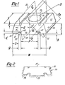
- the self-piercing flush-mountable nut or pierce nut 20 illustrated in Figure 1 includes a generally planar top face 24, a pilot portion 26 having a flat rectangular piercing face 28, a nut bore 30 which extends through the pilot portion and flange portions 32 on opposed sides of the pilot portion having panel supporting faces 34 generally parallel to but spaced from the plane of the piercing face 28.
- a pierce nut functions as an expendable punch in a die set, wherein the piercing face 28 of the pilot portion pierces or punches a slug from a panel and the portion of the panel adjacent the pierced panel edge is deformed into grooves adjacent the pilot portion.
- the pierce nut preferably includes parallel re-entrant grooves 38 in the flange portions 32 on opposed sides of the pilot portion 26.
- the grooves are defined as re-entrant because the width g of the opening of the grooves is less than the width of the grooves spaced from the opening to entrap panel metal during installation.
- the disclosed and preferred embodiment of the re-entrant grooves 38 include opposed relatively inclined side walls 40 and 42 and a bottom wall 44. As will be understood, either or both side walls may be inclined relative to a perpendicular plane through the axis of the groove to define a re-entrant groove or the groove may be made re-entrant during the installation by deforming the flange portions.
- a pierce nut is permanently installed in a panel by an installation apparatus which may be mounted in a reciprocal die press.
- the pierce nut installation head is normally mounted to one die platen and a die button is installed in the opposed die platen.
- the pierce nuts are fed into the installation head, which includes a reciprocal plunger which engages the top face 24 of the pierce nut and drives the piercing face 28 of the pilot portion 26 into engagement with the panel.
- the die button normally includes parallel upstanding clinching lips which are aligned with and received within the re-entrant grooves 38.
- the die button also includes a rectangular opening which receives the pilot portion 26 and the slug pierced from the panel.
- a pierce nut is thus permanently installed in the panel with each stroke of the die press.
- the panel may be simultaneously formed in the die press and several pierce nuts installed with each stroke of the press.
- Pierce nuts are presently formed from rolled metal stock wherein the general outline or configuration of the nut is rolled, forming a continuous strip having the general configuration of the pierce nut shown in Figure 1, including the re-entrant grooves.
- the bottom wall 44 of each groove is preferably joined to the side walls 40 and 42 by arcuate surfaces 46, reducing the likelihood of fracture during the installation of the nut.
- the side walls 54 of the nut preferably include inclined faces 52, reducing the total volume of the nut strip.
- the individual nuts are then cut or sheared from the strip.
- the nut blank is then pierced, forming the nut bore 30 and the nut bore may be internally threaded or tapped.
- the nuts may then be fed in bulk form to the pierce nut installation head and installed in a panel, as described above.
- frangible connector means as described in the above referenced United States patents, may be used to interconnect the nuts in a continuous strip.
- wire grooves 50 are rolled in the nut strip during the rolling operation.
- the wires 58 may then be permanently retained in the wire grooves 50 by knurling or other conventional means.
- the plunger breaks or shears the frangible connector means during the installation of the pierce nut.
- a flush-mounted pierce nut has several advantages over a conventional pierce nut.
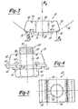
- the pierce nut 20 is permanently installed in a panel 60 and the clinching lips of the die button (not shown) deform the portion 62 of the panel adjacent the pierced panel opening into the re-entrant grooves 38.
- the panel portions 62 are thus entrapped in the grooves, forming a secure mechanical interlock between the panel 60 and the pierce nut 20.
- the panel supporting faces 34 of the flange portions 32 are spaced from the plane of the piercing face 28 (see h in Figure 1), which is generally less than the thickness of the panel 60.
- the pilot piercing face 28 is thus generally flush with the main portion of the panel 60.
- the panel 60 may then be attached to a second structural member 64, such as a panel, as shown in Figure 4.
- a washer 66 is aligned with the nut bore 30 and a bolt 68 having a head portion 70 and a threaded shank portion 72 is threaded into the nut bore, securing the panel 60 to the structural member 64.
- the axial load of the bolt R 3 (see Figure 3) is transmitted through the bearing faces 34 of the flange portions 32 as represented by R 1 and R 2 of Figure 3. This is referred to as the beam load of the nut or the nut and panel assembly.
- the beam load test of the nut 20 simulates the load placed on the nut in the actual nut and panel assembly.
- the reactive force R 3 is transmitted through the flange portions 32, as shown at R and R 2 .
- This force tends to bow the nut as shown by the phantom curve 74.
- a flush-mounted pierce nut of the type disclosed will fail in the nut and panel assembly shown in Figure 4 in one of five shear planes, as shown in Figure 1.
- These shear or fracture planes include P 1 , which is defined through the axis of the nut bore 30, perpendicular to the top and bottom faces of the nut, 24 and 28.
- the second fracture plane P2 is defined at an acute angle through the inner arcuate surface 46 of the re-entrant groove and the axis of the nut bore 30.
- the third fracture plane P 3 is defined through the inner arcuate surface 46 of the groove and the top surface 24 of the nut.
- the fracture plane P3 will be defined through the center of the groove 50 where the nut includes grooves for receiving the frangible connector means. Otherwise, the fracture plane P 3 will be perpendicular to the top face 24. Further, the fracture planes P and P 3 are duplicated on opposed sides of the nut, resulting in five fracture planes.
- the prior practice has been to simply increase the thickness of the nut where fractures are observed.
- the depth of the groove E and the distance between the panel supporting surfaces 34 and the piercing surface 28 is determined by the thickness of the panel to which the nut is installed.
- the diameter of the nut bore is determined by the application, for example a nut for an eight millimeter bolt.
- the nut is simply beefed up to reduce or eliminate the failures.
- the dimensional relationship between the length, width, groove depth, pilot height, etc. has been determined on a trial and error basis.
- a 1 which is the area of the nut in fracture plane P I may be defined as follows:
- the area A 2 of the nut in fracture plane P 2 must be defined in trigonometric functions, as follows: Wherein As will be understood, the area of the nut bore in fracture plane P 2 is an ellipse, wherein Y is equal to one half the major diameter of the ellipse cut by shear plane P 2 , and Y 1 is the length of the plane measured between the inside arcuate surface 46 of the re-entrant groove and the center of the nut at the top face 24.
- P is the width of the pilot piercing face 28
- G is the width of the re-entrant groove 38 at the bottom wall 44
- g is the width of the restricted opening to the re-entrant groove
- angle a is the acute angle between fracture planes P 1 and P 2 .
- A3 which is the area of the nut in fracture plane P 3 , may be defined as follows where the nut does not include grooves 50 in the top face 24 of the nut and the fracture plane P 3 is perpendicular to the top face: where E is the depth of the groove measured between the panel supporting faces 34 and the bottom wall 44 of the groove, h is the pilot height measured between the panel supporting faces 34 of the flange portions and the piercing face 28. K is the stress factor for filleted bars, taking into account the inside radius 46 at the groove bottom wall, which may be found in standard machinery design texts, such as Machine Design, by Shigley, McGraw-Hill (1956), Figure 2-32, p. 36.
- the area A3 may be defined as follows: wherein a is equal to T - (E + F + h) and b is equal to G 2. Substituting for a and b in the equation above, the area A3 of the nut in fracture plane P 3 , may be defined as follows:
- the area equations may then be solved simultaneously for L, assuming that the nut includes grooves 50 in the top face 24 of the nut such that the fracture plane P 3 is defined at an angle to the top face as shown in Figure 1:
- the areas of the panel bearing faces of the flange portions must be sufficient to prevent pull-through of the nut, as defined above, and the width W of the nut is simply the summation of the widths of the pilot P, the re-entrant groove openings (g + g) and the widths of the flange bearing surfaces (C + C).
- the flush-mountable pierce nut of this invention it is now possible to design a nut or redesign the present commercial flush-mountable pierce nut pursuant to this dimensional relationship to define the optimum dimensional relationship such that the beam load of the nut or the beam load of the nut and panel assembly is equal to or greater than the proof load of the bolt, while optimizing the volume of the nut and reducing the material costs.
- the present H-S 22 "Hi-Stress" pierce nut of the Assignee which is designed to accept an eight millimeter threaded bolt, was redesigned pursuant to the above defined dimensional relationship, as now described.
- the area A of the present H-S 22 nut in fracture plane P1 was calculated, as defined above, as 0.065 square inches, A 2 was 0.054 square inches and A3 was 0.048 square inches.
- this pierce nut normally failed in a beam load test in fracture plane P 3 , however, the nut exceeded the minimum proof load by over 2,000 lbs.
- the minimum proof load requirement of an eight millimeter threaded nut, as specified by the automotive industry, is 8,138 lbs.
- the proof load of an H-S 22 pierce nut was, however, 10,426 lbs.
- the minimum thickness of the nut T may be determined from the strength of the nut material and the pitch of the threads by standard calculations.
- the beam strength of the nut or the nut and panel assembly, as defined above, is preferably at least squal to the proof load of the bolt.
- the minimum proof load for a class 9.8, eight millimeter bolt is 5,350 lbs.
- the areas A., A 2 and A3 should then be at least equal to the beam strength divided by the strength of the nut material.
- the panel adds beam strength to the nut and panel assembly. In a rolled steel pierce nut of the type described, the strength of the nut material is approximately 130,500 lbs. per square inch.
- the areas A 1 , A 2 and A3 should be approximately 0.041 square inches, reducing the volume of the nut by approximately twenty seven percent.
- the dimensions E, G, g and h are determined by the panel thickness into which the nut is to be installed.
- D, P and T will be determined by the size of the thread requirement.
- the equation may then be solved for L,' fixing the final dimensional relation of the nut, which resulted in a twenty seven percent reduction in the volume of the H-S 22 nut, as described above.
- Figure 2 illustrates the advantage of the flush-mountable nut 20 of this invention having the dimensional relation described above.
- the nut 20 has been redesigned from the configuration 56 shown in phantom such that the areas in the shear planes are substantially equal reducing the material cost without sacrificing the integrity or strength of the nut in the nut and panel assembly.
- the flush-mountable pierce nut of the type described herein by determining the fracture planes by experimentation and designing the nut such that the fracture planes are approximately equal and the strength of the nut or the nut and panel assembly in the fracture planes exceeds the minimum proof load of the bolt.
- the flush-mountable nut of this invention will be designed to withstand the minimum proof load of the classification of the bolt specified for the application. This relation will optimize the volume of the nut, reducing the material costs while maintaining the integrity of the nut.
Landscapes
- Engineering & Computer Science (AREA)
- General Engineering & Computer Science (AREA)
- Mechanical Engineering (AREA)
- Automatic Assembly (AREA)
- Connection Of Plates (AREA)
- Transplanting Machines (AREA)
- Dowels (AREA)
- Valve-Gear Or Valve Arrangements (AREA)
Applications Claiming Priority (2)
| Application Number | Priority Date | Filing Date | Title |
|---|---|---|---|
| US06/685,418 US4971499A (en) | 1984-12-24 | 1984-12-24 | Nut and panel assembly |
| US685418 | 1984-12-24 |
Publications (2)
| Publication Number | Publication Date |
|---|---|
| EP0186064A1 true EP0186064A1 (de) | 1986-07-02 |
| EP0186064B1 EP0186064B1 (de) | 1991-07-31 |
Family
ID=24752127
Family Applications (1)
| Application Number | Title | Priority Date | Filing Date |
|---|---|---|---|
| EP85115897A Expired - Lifetime EP0186064B1 (de) | 1984-12-24 | 1985-12-13 | Bündig montierbare Stanzmutter |
Country Status (7)
| Country | Link |
|---|---|
| US (1) | US4971499A (de) |
| EP (1) | EP0186064B1 (de) |
| JP (1) | JPS61223315A (de) |
| KR (1) | KR910002213B1 (de) |
| CA (1) | CA1270390A (de) |
| DE (1) | DE3583663D1 (de) |
| GB (1) | GB2170290B (de) |
Families Citing this family (26)
| Publication number | Priority date | Publication date | Assignee | Title |
|---|---|---|---|---|
| US5446957A (en) * | 1993-11-22 | 1995-09-05 | Ford Motor Company | Apparatus and method for forming a vehicle panel having a preplugged |
| DE102004045159A1 (de) | 2004-01-29 | 2005-09-01 | Profil Verbindungstechnik Gmbh & Co. Kg | Verfahren zur Herstellung von Hohlkörperelementen, Hohlkörperelement sowie Folgeverbundwerkzeug zur Durchführung des Verfahrens |
| US7090451B2 (en) * | 2000-03-31 | 2006-08-15 | Profil Verbindungstechnik Gmbh & Co. Kg | Method for producing hollow bodies, profile for use in said method, hollow body, assembly unit and mold |
| US6406237B1 (en) | 2000-12-05 | 2002-06-18 | Fabristeel Products, Inc. | Method of attaching a fastener element to a panel and fastener element and panel assembly |
| EP1417420B1 (de) * | 2001-08-15 | 2006-08-30 | Whitesell International Corporation | Selbstsicherndes befestigungselement |
| EP1548299B1 (de) * | 2001-08-15 | 2007-02-14 | Whitesell International Corporation | Streifen aus Befestigungselementen sowie Verfahren zu deren Herstellung und Zuführung |
| ATE354036T1 (de) * | 2001-08-15 | 2007-03-15 | Whitesell Int Corp | Streifen aus befestigungselementen sowie verfahren zu deren herstellung und zuführung |
| DE20205192U1 (de) * | 2002-04-03 | 2002-11-07 | Profil Verbindungstechnik GmbH & Co. KG, 61381 Friedrichsdorf | Profil zur Herstellung von Hohlkörperelementen, Hohlkörperelement sowie Zusammenbauteil |
| ATE374655T1 (de) * | 2002-11-27 | 2007-10-15 | Whitesell Int Corp | Selbstbefestigendes weibliches befestigungselement und herstellungsverfahren dafür |
| EP1559488B1 (de) | 2004-01-29 | 2017-04-26 | PROFIL-Verbindungstechnik GmbH & Co. KG | Verfahren zur Herstellung von Hohlkörperelement sowie Folgeverbundwerkzeug zur Durchführung des Verfahrens |
| US7338245B2 (en) * | 2004-03-29 | 2008-03-04 | Whitesell International Corp. | Self-attaching nut |
| US6997659B2 (en) * | 2004-03-29 | 2006-02-14 | Whitesell International Corporation | Self-attaching fastener |
| DE102004017866A1 (de) * | 2004-04-13 | 2005-11-03 | Profil-Verbindungstechnik Gmbh & Co. Kg | Verfahren zur Herstellung von Hohlkörperelementen, Hohlkörperelement, Zusammenbauteil sowie Folgeverbundwerkzeug zur Durchführung des Verfahrens |
| US7540699B2 (en) * | 2004-04-15 | 2009-06-02 | Stafast Products, Inc. | Adjustable threshold fastener with flanges |
| US7237996B2 (en) * | 2004-05-18 | 2007-07-03 | Fabristeel Products, Inc. | Nut feed system and nut |
| US7152297B2 (en) * | 2004-06-02 | 2006-12-26 | Whitesell International Corporation | Self-attaching female fastener, die set and method of attachment |
| US7367893B2 (en) * | 2005-05-05 | 2008-05-06 | Whitesell International Corporation | Fastener manufacturing apparatus and method |
| US7975522B2 (en) * | 2005-05-05 | 2011-07-12 | Whitesell International Corporation | Fastener manufacturing assembly and method |
| DE102005024220A1 (de) | 2005-05-25 | 2006-11-30 | Profil Verbindungstechnik Gmbh & Co. Kg | Verfahren zum Herstellen von Hohlkörperelementen, Hohlkörperelement, Zusammenbauteil, Folgeverbundwerkzeug zum Herstellen von Hohlkörperelementen sowie Walzwerk |
| US7674081B2 (en) | 2006-09-19 | 2010-03-09 | Stafast Products, Inc. | Hopper fed tee-nut having counterbore with nylon lock |
| US8672597B2 (en) | 2007-02-09 | 2014-03-18 | Stafast Products, Inc. | Fastener |
| US8485910B2 (en) | 2008-08-18 | 2013-07-16 | Stafast Products, Inc. | Sealed end t-nut |
| US20110003647A1 (en) * | 2009-07-02 | 2011-01-06 | Fastener Advance Products | Pierce nut manufacturing method and apparatus |
| US9212676B2 (en) | 2009-11-18 | 2015-12-15 | Stafast Products. Inc. | Fastener |
| US20120181197A1 (en) | 2011-01-17 | 2012-07-19 | Stafast Products, Inc. | Collated t-nut apparatus |
| USD931095S1 (en) * | 2019-11-24 | 2021-09-21 | Pmc Industries, Inc. | Slot nut |
Citations (5)
| Publication number | Priority date | Publication date | Assignee | Title |
|---|---|---|---|---|
| US3439723A (en) * | 1962-03-14 | 1969-04-22 | Multifastener Corp | Nut-panel assembly |
| US3648747A (en) * | 1969-10-20 | 1972-03-14 | Multifastener Corp | Nut and panel assembly and method of making same |
| US3711931A (en) * | 1971-04-01 | 1973-01-23 | Multifastener Corp | Method of forming fastener strip |
| US4015650A (en) * | 1975-08-15 | 1977-04-05 | Anderson James C | Caged nut |
| US4313261A (en) * | 1980-01-11 | 1982-02-02 | Multifastener Corporation | Nut installation apparatus |
Family Cites Families (5)
| Publication number | Priority date | Publication date | Assignee | Title |
|---|---|---|---|---|
| US3878599A (en) * | 1969-07-11 | 1975-04-22 | Multifastener Corp | Method of forming a nut and panel assembly |
| US3845860A (en) * | 1971-04-01 | 1974-11-05 | Multifastener Corp | Fastener strip |
| JPS4826096A (de) * | 1971-08-05 | 1973-04-05 | ||
| US3926236A (en) * | 1972-10-30 | 1975-12-16 | Multifastener Corp | Self-fastening nut, panel assembly and apparatus |
| JPS597048B2 (ja) * | 1979-11-17 | 1984-02-16 | 有限会社新城製作所 | クリンチナツト及びその取付方法 |
-
1984
- 1984-12-24 US US06/685,418 patent/US4971499A/en not_active Expired - Lifetime
-
1985
- 1985-11-27 CA CA000496295A patent/CA1270390A/en not_active Expired - Lifetime
- 1985-12-05 KR KR1019850009223A patent/KR910002213B1/ko not_active Expired
- 1985-12-13 EP EP85115897A patent/EP0186064B1/de not_active Expired - Lifetime
- 1985-12-13 DE DE8585115897T patent/DE3583663D1/de not_active Expired - Lifetime
- 1985-12-20 GB GB08531470A patent/GB2170290B/en not_active Expired
- 1985-12-23 JP JP60288057A patent/JPS61223315A/ja active Granted
Patent Citations (5)
| Publication number | Priority date | Publication date | Assignee | Title |
|---|---|---|---|---|
| US3439723A (en) * | 1962-03-14 | 1969-04-22 | Multifastener Corp | Nut-panel assembly |
| US3648747A (en) * | 1969-10-20 | 1972-03-14 | Multifastener Corp | Nut and panel assembly and method of making same |
| US3711931A (en) * | 1971-04-01 | 1973-01-23 | Multifastener Corp | Method of forming fastener strip |
| US4015650A (en) * | 1975-08-15 | 1977-04-05 | Anderson James C | Caged nut |
| US4313261A (en) * | 1980-01-11 | 1982-02-02 | Multifastener Corporation | Nut installation apparatus |
Also Published As
| Publication number | Publication date |
|---|---|
| DE3583663D1 (de) | 1991-09-05 |
| KR910002213B1 (ko) | 1991-04-08 |
| GB2170290A (en) | 1986-07-30 |
| GB8531470D0 (en) | 1986-02-05 |
| GB2170290B (en) | 1988-06-22 |
| JPH0427402B2 (de) | 1992-05-11 |
| CA1270390A (en) | 1990-06-19 |
| JPS61223315A (ja) | 1986-10-03 |
| EP0186064B1 (de) | 1991-07-31 |
| US4971499A (en) | 1990-11-20 |
| KR860005155A (ko) | 1986-07-18 |
Similar Documents
| Publication | Publication Date | Title |
|---|---|---|
| US4971499A (en) | Nut and panel assembly | |
| EP0553822B1 (de) | Selbstsichernde Befestigung sowie Matrize zu ihrer Montage | |
| US3926236A (en) | Self-fastening nut, panel assembly and apparatus | |
| US5549430A (en) | Self-attaching fastener and installation die | |
| US3810291A (en) | Installation die and nut and method of installing a nut in a panel | |
| US3845860A (en) | Fastener strip | |
| EP0268302B1 (de) | Befestigungsmittel und Verfahren zum Anbringen desselben an plattenförmiges Material | |
| US4459073A (en) | Fasteners with piercing and riveting performance | |
| EP0669473A1 (de) | Selbstsicherndes Befestigungselement und Verfahren zu dessen Herstellung und Einbau | |
| US6997659B2 (en) | Self-attaching fastener | |
| US3829957A (en) | Method of assembling a self-fastening nut and a panel | |
| US3920059A (en) | Combination of relatively thin sheet of metal and pierce nut | |
| US20040130932A1 (en) | Self-piercing element, method of attachment and die member | |
| US4124050A (en) | Action piercing fastener | |
| EP1645357A2 (de) | Drehmoment widerstehendes Befestigungselement | |
| US4370794A (en) | Clinch nut and method of installing same | |
| US20060009299A1 (en) | Self attaching female fasteners and method of forming female fastener elements | |
| US7338245B2 (en) | Self-attaching nut | |
| US3985172A (en) | Panel extruding nut and assembly | |
| US7704151B2 (en) | Self-attaching female fasteners, method of forming same and strip of interconnected fasteners | |
| US3969809A (en) | Self-fastening nut, panel assembly and apparatus | |
| EP1756436B1 (de) | Selbst befestigendes aufnahme-befestigungsglied, gesenksatz und befestigungsverfahren | |
| GB2161571A (en) | Pierce nut, panel assembly and attachment method | |
| US3927452A (en) | Apparatus for assembling self-fastening nut to a panel | |
| CA2143363C (en) | Self-attaching fastener and method of installation |
Legal Events
| Date | Code | Title | Description |
|---|---|---|---|
| PUAI | Public reference made under article 153(3) epc to a published international application that has entered the european phase |
Free format text: ORIGINAL CODE: 0009012 |
|
| AK | Designated contracting states |
Kind code of ref document: A1 Designated state(s): DE FR IT |
|
| 17P | Request for examination filed |
Effective date: 19861215 |
|
| 17Q | First examination report despatched |
Effective date: 19880714 |
|
| GRAA | (expected) grant |
Free format text: ORIGINAL CODE: 0009210 |
|
| AK | Designated contracting states |
Kind code of ref document: B1 Designated state(s): DE FR IT |
|
| ITF | It: translation for a ep patent filed | ||
| REF | Corresponds to: |
Ref document number: 3583663 Country of ref document: DE Date of ref document: 19910905 |
|
| ET | Fr: translation filed | ||
| PLBE | No opposition filed within time limit |
Free format text: ORIGINAL CODE: 0009261 |
|
| STAA | Information on the status of an ep patent application or granted ep patent |
Free format text: STATUS: NO OPPOSITION FILED WITHIN TIME LIMIT |
|
| 26N | No opposition filed | ||
| PGFP | Annual fee paid to national office [announced via postgrant information from national office to epo] |
Ref country code: FR Payment date: 20041208 Year of fee payment: 20 |
|
| PGFP | Annual fee paid to national office [announced via postgrant information from national office to epo] |
Ref country code: DE Payment date: 20041209 Year of fee payment: 20 |