EP0186078A2 - Tête de mélange pour mélanger au moins deux composants synthétiques qui forment lors de leur réaction une mousse, en particulier du polyuréthane - Google Patents
Tête de mélange pour mélanger au moins deux composants synthétiques qui forment lors de leur réaction une mousse, en particulier du polyuréthane Download PDFInfo
- Publication number
- EP0186078A2 EP0186078A2 EP85115969A EP85115969A EP0186078A2 EP 0186078 A2 EP0186078 A2 EP 0186078A2 EP 85115969 A EP85115969 A EP 85115969A EP 85115969 A EP85115969 A EP 85115969A EP 0186078 A2 EP0186078 A2 EP 0186078A2
- Authority
- EP
- European Patent Office
- Prior art keywords
- mixing chamber
- mixing
- throttle element
- throttle
- face
- Prior art date
- Legal status (The legal status is an assumption and is not a legal conclusion. Google has not performed a legal analysis and makes no representation as to the accuracy of the status listed.)
- Granted
Links
- 239000006260 foam Substances 0.000 title claims 2
- 229920002635 polyurethane Polymers 0.000 title claims 2
- 239000004814 polyurethane Substances 0.000 title claims 2
- 238000004140 cleaning Methods 0.000 claims abstract description 12
- 229920003023 plastic Polymers 0.000 claims description 2
- 239000004033 plastic Substances 0.000 claims description 2
- 210000002105 tongue Anatomy 0.000 abstract description 10
- 239000000203 mixture Substances 0.000 abstract description 7
- 230000006978 adaptation Effects 0.000 abstract 1
- 230000000694 effects Effects 0.000 description 3
- 238000009825 accumulation Methods 0.000 description 1
- 230000009286 beneficial effect Effects 0.000 description 1
- 230000002349 favourable effect Effects 0.000 description 1
- 239000000463 material Substances 0.000 description 1
- 238000000034 method Methods 0.000 description 1
- 230000001360 synchronised effect Effects 0.000 description 1
Images
Classifications
-
- B—PERFORMING OPERATIONS; TRANSPORTING
- B29—WORKING OF PLASTICS; WORKING OF SUBSTANCES IN A PLASTIC STATE IN GENERAL
- B29B—PREPARATION OR PRETREATMENT OF THE MATERIAL TO BE SHAPED; MAKING GRANULES OR PREFORMS; RECOVERY OF PLASTICS OR OTHER CONSTITUENTS OF WASTE MATERIAL CONTAINING PLASTICS
- B29B7/00—Mixing; Kneading
- B29B7/74—Mixing; Kneading using other mixers or combinations of mixers, e.g. of dissimilar mixers ; Plant
- B29B7/76—Mixers with stream-impingement mixing head
- B29B7/7663—Mixers with stream-impingement mixing head the mixing head having an outlet tube with a reciprocating plunger, e.g. with the jets impinging in the tube
- B29B7/7673—Mixers with stream-impingement mixing head the mixing head having an outlet tube with a reciprocating plunger, e.g. with the jets impinging in the tube having additional mixing arrangements
-
- B—PERFORMING OPERATIONS; TRANSPORTING
- B29—WORKING OF PLASTICS; WORKING OF SUBSTANCES IN A PLASTIC STATE IN GENERAL
- B29C—SHAPING OR JOINING OF PLASTICS; SHAPING OF MATERIAL IN A PLASTIC STATE, NOT OTHERWISE PROVIDED FOR; AFTER-TREATMENT OF THE SHAPED PRODUCTS, e.g. REPAIRING
- B29C44/00—Shaping by internal pressure generated in the material, e.g. swelling or foaming ; Producing porous or cellular expanded plastics articles
- B29C44/34—Auxiliary operations
- B29C44/3442—Mixing, kneading or conveying the foamable material
-
- B—PERFORMING OPERATIONS; TRANSPORTING
- B29—WORKING OF PLASTICS; WORKING OF SUBSTANCES IN A PLASTIC STATE IN GENERAL
- B29C—SHAPING OR JOINING OF PLASTICS; SHAPING OF MATERIAL IN A PLASTIC STATE, NOT OTHERWISE PROVIDED FOR; AFTER-TREATMENT OF THE SHAPED PRODUCTS, e.g. REPAIRING
- B29C44/00—Shaping by internal pressure generated in the material, e.g. swelling or foaming ; Producing porous or cellular expanded plastics articles
- B29C44/34—Auxiliary operations
- B29C44/58—Moulds
- B29C44/581—Closure devices for pour holes
Definitions
- the invention relates to a mixing head according to the preamble of claim 1.
- the throttle element is provided in order to form a throttling point after the entry of the components to be mixed into the mixing chamber and before it leaves this mixing chamber, and the mixture is favorable should influence.
- the throttle element has a circular cross section. Its front face is flat. If throttling is to take place, the throttling element is moved more or less far into the mixing chamber. Since the end face is flat, the throttle element can be moved relatively far into the mixing chamber, namely until the corresponding points on the end face abut the mixing chamber wall. But then there remains a more or less large opening, which is semicircular in cross section or represents a segment of a circle.
- the throttle element can be pushed in relatively far, but then a relatively large, unthrottled cross section remains to the left and right of the throttle element. If the cross section of the throttling member is as large as that of the mixing chamber, then the throttling member can only be advanced up to half and there remains a through opening for the component mixture in a semicircular shape in front of its end face.
- Such a throttle body with a flat end face, in its retracted position in the housing in front of its end face leaves a space in connection with the mixing chamber, approximately V-shaped or U-shaped in cross-section, which, when the cleaning piston moves in the direction of the outlet opening of the mixing chamber is not painted over. In this space in front of the throttle element, component residues collect that the cleaning piston cannot remove and that are undesirable.
- the invention has for its object to provide a mixing head of the type mentioned, in which on the one hand there is no accumulation of component residues in front of the end face of the throttle body, i.e. complete cleaning is possible, and on the other hand a good throttling effect can be achieved.
- the shape of the end face of the throttle element is adapted to the contour of the mixing chamber, there is no space in which material can accumulate or complete cleaning by the ejection piston is possible. If the throttle element is now rotated by 90 ° when advancing into the mixing position, the two tongues, which are formed by the appropriate design of the end face, rotate up and down in relation to the mixing chamber, so that the throttle element is much further into the Mixing chamber is retractable, since the tongues practically only abut the mixing chamber wall on the lateral surface opposite the throttle element. A very large part of the cross section of the mixing chamber is filled by the throttle body in this way. When the throttle member is withdrawn, a reverse rotation takes place, so that after returning to its starting position it returns to its old position and completely fills its bore so that the ejection piston can then carry out its cleaning stroke and completely clean the mixing chamber.
- the rotary movement which can preferably be synchronized with the movement into the throttle position, can be carried out in a wide variety of ways.
- One possibility is given in claims 2 and 3.
- the mixing head is designed as specified in claim 4, then small open cross-sectional areas remain to the left and right of the throttle element in the mixing chamber, through which the component mixture is pressed around the throttle element. This can have a beneficial effect on the mixture.
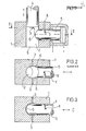
- the mixing head shown in the drawing is basically known and only shown schematically. It consists of a housing 1, in which a mixing chamber 2 is formed, which in this embodiment has a circular cross-section, although other cross-sectional shapes are also possible. Two inlet openings 3 lead into the mixing chamber for the plastic components to be mixed. Only an entry opening can be seen. A cleaning piston 4, which is adapted to the cross section of the mixing chamber, can be moved back and forth in the mixing chamber. In Fig. 1 the mixing position is shown, i.e. the entry openings are free. If a mixing process, i.e. a "shot" is finished, the cleaning piston 4 is moved in the direction of the outlet opening 9, closing the inlet openings and mechanically cleaning the mixing chamber.
- a throttle element 5 is likewise arranged with a circular cross section perpendicular to the mixing chamber axis. This throttle element is adapted in its front end face to the contour of the mixing chamber 2, as is best seen when looking at FIG. 2. There are practically two tongues 6, which lie laterally in the illustration according to FIG. 2. A groove 7 of corresponding pitch is formed in the throttle element, into which a guide pin 8 projects. The connection of guide pin 8 and groove 7 is a positive.
- the throttle element 5 is pushed into the mixing chamber 2 by a corresponding device, for example hydraulically.
- the guide pin 8 slides in the groove 7, so that the throttle body is inevitably rotated according to the slope of the Nu t 7.
- the ratios are chosen so that the throttle element has been rotated by 90 ° after reaching its end position (FIG. 3).
- the tongues 6 lying laterally in FIG. 2 are then in the position according to FIG. 3 above and below. It is readily apparent that the throttle body is forced by this rotation can be moved much further into the mixing chamber 2, since the tongues 6 only abut the wall sections of the mixing chamber 2 opposite the throttle element.
- the tongues 6 would hit the mixing chamber wall much earlier. There would also remain a very large, approximately lenticular opening, the throttling effect of which would be correspondingly low.
- the rotation of the throttle member during advancement not only enables the throttle member to be retracted further, but the end face, the shape of which is adapted to the contour of the mixing chamber, is also placed vertically, so that the rear region of the end face of the throttle member is in the throttle position is not effective because it is covered by the tongues.
Landscapes
- Engineering & Computer Science (AREA)
- Mechanical Engineering (AREA)
- Processing And Handling Of Plastics And Other Materials For Molding In General (AREA)
- Polyurethanes Or Polyureas (AREA)
- Manufacture Of Porous Articles, And Recovery And Treatment Of Waste Products (AREA)
Priority Applications (1)
| Application Number | Priority Date | Filing Date | Title |
|---|---|---|---|
| AT85115969T ATE50725T1 (de) | 1984-12-21 | 1985-12-13 | Mischkopf zum vermischen mindestens zweier bei ihrer reaktion schaumstoff bildender kunststoffkomponenten, insbesondere polyurethan. |
Applications Claiming Priority (2)
| Application Number | Priority Date | Filing Date | Title |
|---|---|---|---|
| DE19843446818 DE3446818A1 (de) | 1984-12-21 | 1984-12-21 | Mischkopf zum vermischen mindestens zweier bei ihrer reaktion schaumstoff bildender kunststoffkomponenten, insbesondere polyurethan |
| DE3446818 | 1984-12-21 |
Publications (3)
| Publication Number | Publication Date |
|---|---|
| EP0186078A2 true EP0186078A2 (fr) | 1986-07-02 |
| EP0186078A3 EP0186078A3 (en) | 1988-08-31 |
| EP0186078B1 EP0186078B1 (fr) | 1990-03-07 |
Family
ID=6253517
Family Applications (1)
| Application Number | Title | Priority Date | Filing Date |
|---|---|---|---|
| EP85115969A Expired - Lifetime EP0186078B1 (fr) | 1984-12-21 | 1985-12-13 | Tête de mélange pour mélanger au moins deux composants synthétiques qui forment lors de leur réaction une mousse, en particulier du polyuréthane |
Country Status (5)
| Country | Link |
|---|---|
| US (1) | US4702890A (fr) |
| EP (1) | EP0186078B1 (fr) |
| JP (1) | JPS61199914A (fr) |
| AT (1) | ATE50725T1 (fr) |
| DE (2) | DE3446818A1 (fr) |
Cited By (1)
| Publication number | Priority date | Publication date | Assignee | Title |
|---|---|---|---|---|
| EP0256157A1 (fr) * | 1986-08-16 | 1988-02-24 | IBW Ingenieur-Büro Woitzel GmbH | Tête de mélange pour mélanger au moins deux composants dont la réaction donne un produit plastique |
Families Citing this family (1)
| Publication number | Priority date | Publication date | Assignee | Title |
|---|---|---|---|---|
| US5186905A (en) * | 1991-07-16 | 1993-02-16 | Sealed Air Corporation | Cartridge port design for dispensing foam precursors |
Family Cites Families (4)
| Publication number | Priority date | Publication date | Assignee | Title |
|---|---|---|---|---|
| DE2847504A1 (de) * | 1978-11-02 | 1980-05-14 | Desma Werke Gmbh | Mischkopf zum mischen von wenigstens zwei fliessfaehigen materialkomponenten |
| DE3005231A1 (de) * | 1980-02-13 | 1981-08-20 | Krauss-Maffei AG, 8000 München | Mischkopf mit einem staubkoerper |
| DE3011132A1 (de) * | 1980-03-22 | 1981-10-01 | Desma-Werke Gmbh, 2807 Achim | Mischkopf zum vermischen und austragen von wenigstens zwei fliessfaehigen materialkomponenten |
| DE3144920A1 (de) * | 1981-11-12 | 1983-05-26 | Krauss-Maffei AG, 8000 München | Mischkopf |
-
1984
- 1984-12-21 DE DE19843446818 patent/DE3446818A1/de not_active Withdrawn
-
1985
- 1985-12-13 DE DE8585115969T patent/DE3576292D1/de not_active Expired - Lifetime
- 1985-12-13 EP EP85115969A patent/EP0186078B1/fr not_active Expired - Lifetime
- 1985-12-13 AT AT85115969T patent/ATE50725T1/de not_active IP Right Cessation
- 1985-12-18 JP JP60283185A patent/JPS61199914A/ja active Pending
- 1985-12-18 US US06/810,167 patent/US4702890A/en not_active Expired - Fee Related
Cited By (1)
| Publication number | Priority date | Publication date | Assignee | Title |
|---|---|---|---|---|
| EP0256157A1 (fr) * | 1986-08-16 | 1988-02-24 | IBW Ingenieur-Büro Woitzel GmbH | Tête de mélange pour mélanger au moins deux composants dont la réaction donne un produit plastique |
Also Published As
| Publication number | Publication date |
|---|---|
| JPS61199914A (ja) | 1986-09-04 |
| EP0186078A3 (en) | 1988-08-31 |
| EP0186078B1 (fr) | 1990-03-07 |
| DE3576292D1 (de) | 1990-04-12 |
| ATE50725T1 (de) | 1990-03-15 |
| US4702890A (en) | 1987-10-27 |
| DE3446818A1 (de) | 1986-06-26 |
Similar Documents
| Publication | Publication Date | Title |
|---|---|---|
| DE2538437C3 (de) | Mischvorrichtung für Mehrkomponentenkunststoffe mit Poren- oder Zellenstruktur, insbesondere Polyurethan | |
| DE2907938A1 (de) | Vorrichtung fuer die mischung und verspritzung von miteinander reagierenden fluessigen komponenten fuer die kunststoffteileformung | |
| DE918670C (de) | Schraubengetriebe | |
| DE19549053C2 (de) | Sicherheitsschloß mit einem Schließzylinder und einem Schlüssel mit flachem Schaft | |
| DE1938543B2 (de) | Vorrichtung zum Wickeln von Vliesen aus parallelen Verstaerkungsfaeden | |
| DE2810070C2 (de) | Schließvorrichtung für Füllstationen von horizontal wirkenden Strangpressen | |
| DE2939323C2 (de) | Vorrichtung zur Führung von bewegbaren Fensterscheiben in Kraftfahrzeugkarosserien | |
| EP0186078B1 (fr) | Tête de mélange pour mélanger au moins deux composants synthétiques qui forment lors de leur réaction une mousse, en particulier du polyuréthane | |
| DE9410787U1 (de) | Vorrichtung zum Auftragen von Abdichtungsmaterial auf Spundbohlenklauen und Spundbohlenklauen und Spundbohle mit Dichtung | |
| DE2815460C3 (de) | Mischvorrichtung für Mehrkomponentenkunststoffe, insbesondere Polyurethan | |
| DE3423979A1 (de) | Schrauben-schraubenmutter-kupplung mit kugelumlauf und verfahren zu ihrem zusammenbau | |
| DE1921714A1 (de) | Weiche fuer eine Fahrzeug-Fuehrungsbahn | |
| DE3638835A1 (de) | Elektronischer baustein des dreh-typs | |
| DE3047395C2 (fr) | ||
| EP0787054A1 (fr) | Procede de decoupage d'un corps moule | |
| DE19509674C2 (de) | Scharnierrohling, bestehend aus einem ersten Scharnierteil-Rohling und einem zweiten Scharnierteil-Rohling, sowie Verfahren zu dessen Herstellung | |
| DE3524551C2 (fr) | ||
| DE8527095U1 (de) | Dichtungsstreifen für First- und Gratabdeckungen | |
| DE3335437C2 (fr) | ||
| EP0249054A2 (fr) | Dispositif pour la fabrication d'un mélange réactif de composants pouvant être coulés pour former un matériau en plastic massif ou en mousse de plastique | |
| DE3603430C2 (fr) | ||
| DE3608190C2 (fr) | ||
| DE3037023C2 (fr) | ||
| DE102020102289A1 (de) | Vorrichtung und Verfahren zum Aufbringen einer Reinigungsflüssigkeit auf ein Fahrzeugteil | |
| DE3617287A1 (de) | Vorrichtung zum erzeugen eines vorzugsweise chemisch reaktionsfaehigen gemisches aus mindestens zwei kunststoffkomponenten |
Legal Events
| Date | Code | Title | Description |
|---|---|---|---|
| PUAI | Public reference made under article 153(3) epc to a published international application that has entered the european phase |
Free format text: ORIGINAL CODE: 0009012 |
|
| AK | Designated contracting states |
Kind code of ref document: A2 Designated state(s): AT BE CH DE FR GB IT LI NL SE |
|
| RAP1 | Party data changed (applicant data changed or rights of an application transferred) |
Owner name: ELASTOGRAN POLYURETHANE GMBH |
|
| PUAL | Search report despatched |
Free format text: ORIGINAL CODE: 0009013 |
|
| AK | Designated contracting states |
Kind code of ref document: A3 Designated state(s): AT BE CH DE FR GB IT LI NL SE |
|
| 17P | Request for examination filed |
Effective date: 19880801 |
|
| 17Q | First examination report despatched |
Effective date: 19890602 |
|
| GRAA | (expected) grant |
Free format text: ORIGINAL CODE: 0009210 |
|
| AK | Designated contracting states |
Kind code of ref document: B1 Designated state(s): AT BE CH DE FR GB IT LI NL SE |
|
| PG25 | Lapsed in a contracting state [announced via postgrant information from national office to epo] |
Ref country code: SE Effective date: 19900307 Ref country code: GB Effective date: 19900307 Ref country code: FR Effective date: 19900307 Ref country code: BE Effective date: 19900307 |
|
| REF | Corresponds to: |
Ref document number: 50725 Country of ref document: AT Date of ref document: 19900315 Kind code of ref document: T |
|
| ITF | It: translation for a ep patent filed | ||
| REF | Corresponds to: |
Ref document number: 3576292 Country of ref document: DE Date of ref document: 19900412 |
|
| EN | Fr: translation not filed | ||
| GBV | Gb: ep patent (uk) treated as always having been void in accordance with gb section 77(7)/1977 [no translation filed] | ||
| PG25 | Lapsed in a contracting state [announced via postgrant information from national office to epo] |
Ref country code: AT Effective date: 19901213 |
|
| PLBE | No opposition filed within time limit |
Free format text: ORIGINAL CODE: 0009261 |
|
| STAA | Information on the status of an ep patent application or granted ep patent |
Free format text: STATUS: NO OPPOSITION FILED WITHIN TIME LIMIT |
|
| ITTA | It: last paid annual fee | ||
| 26N | No opposition filed | ||
| PGFP | Annual fee paid to national office [announced via postgrant information from national office to epo] |
Ref country code: CH Payment date: 19921112 Year of fee payment: 8 |
|
| PGFP | Annual fee paid to national office [announced via postgrant information from national office to epo] |
Ref country code: DE Payment date: 19921219 Year of fee payment: 8 |
|
| PGFP | Annual fee paid to national office [announced via postgrant information from national office to epo] |
Ref country code: NL Payment date: 19921231 Year of fee payment: 8 |
|
| PG25 | Lapsed in a contracting state [announced via postgrant information from national office to epo] |
Ref country code: LI Effective date: 19931231 Ref country code: CH Effective date: 19931231 |
|
| PG25 | Lapsed in a contracting state [announced via postgrant information from national office to epo] |
Ref country code: NL Effective date: 19940701 |
|
| NLV4 | Nl: lapsed or anulled due to non-payment of the annual fee | ||
| REG | Reference to a national code |
Ref country code: CH Ref legal event code: PL |
|
| PG25 | Lapsed in a contracting state [announced via postgrant information from national office to epo] |
Ref country code: DE Effective date: 19940901 |