EP0186123A2 - Système d'entraînement pour véhicule - Google Patents
Système d'entraînement pour véhicule Download PDFInfo
- Publication number
- EP0186123A2 EP0186123A2 EP85116174A EP85116174A EP0186123A2 EP 0186123 A2 EP0186123 A2 EP 0186123A2 EP 85116174 A EP85116174 A EP 85116174A EP 85116174 A EP85116174 A EP 85116174A EP 0186123 A2 EP0186123 A2 EP 0186123A2
- Authority
- EP
- European Patent Office
- Prior art keywords
- gear
- shaft
- output shaft
- transaxle
- drive system
- Prior art date
- Legal status (The legal status is an assumption and is not a legal conclusion. Google has not performed a legal analysis and makes no representation as to the accuracy of the status listed.)
- Withdrawn
Links
Images




Classifications
-
- B—PERFORMING OPERATIONS; TRANSPORTING
- B60—VEHICLES IN GENERAL
- B60K—ARRANGEMENT OR MOUNTING OF PROPULSION UNITS OR OF TRANSMISSIONS IN VEHICLES; ARRANGEMENT OR MOUNTING OF PLURAL DIVERSE PRIME-MOVERS IN VEHICLES; AUXILIARY DRIVES FOR VEHICLES; INSTRUMENTATION OR DASHBOARDS FOR VEHICLES; ARRANGEMENTS IN CONNECTION WITH COOLING, AIR INTAKE, GAS EXHAUST OR FUEL SUPPLY OF PROPULSION UNITS IN VEHICLES
- B60K17/00—Arrangement or mounting of transmissions in vehicles
- B60K17/34—Arrangement or mounting of transmissions in vehicles for driving both front and rear wheels, e.g. four wheel drive vehicles
- B60K17/344—Arrangement or mounting of transmissions in vehicles for driving both front and rear wheels, e.g. four wheel drive vehicles having a transfer gear
Definitions
- the present invention relates in general to vehicle drive system and more particularly to a vehicle drive system for a longitudinal engine layout.
- transverse F-F or R-R vehicle a power unit for a transverse-front-engine front-drive or transverse- rear-engine rear-drive vehicle
- a transverse F-F or R-R vehicle a power unit for a four wheel drive vehicle of a longitudinal engine layout as is disclosed in the Japanese Provisional Patent Publication Nos. 59-20371 and 59-20372.
- the output of the power unit is transferred through front and rear final drive units to front and rear road wheels.
- a power unit for a transverse F-F or R-R vehicle usually consists of an engine having an engine block of which the longitudinal ends are spaced laterally of the vehicle and a transaxle attached to one longitudinal end of the engine block.
- the transaxle incorporates a final drive unit consisting of a pinion at an end of a drive shaft, a ring gear meshing with the pinion and a differential mechanism.
- the pinion and ring gear constitute a reduction gear mechanism for reducing the output speed of the power unit.
- the drive system comprises a longitudinal engine, a transaxle in line with the engine and having an output shaft and a final drive unit drivingly connected to the output shaft for transmitting engine power to a pair of road wheels.
- the above structure may substantially follow the conventional fashion.
- a speed-up mechanism is incorporated in the transaxle to increase output speed of the output shaft.
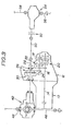
- an engine is generally indicated by the reference numeral 10 and a transmission or transaxle by 12.
- the engine 10 and the transaxle 12 are connected to each other in such a manner that an output shaft 14 of the engine 10 and a mainshaft 16 of the transaxle 12 are axially aligned with each other.
- the output shaft 14 and the mainshaft 16 are so arranged as to be parallel with a longitudinal center axis of a vehicle (a right-hand part of the drawing indicates a forward part of the vehicle and a left-hand part does a rearward part).
- the transaxle 12 includes a counter shaft 18 in parallel with the mainshaft 16, a first group of gears 20 installed on the mainshaft 16 and a second group of gears 22 installed on the counter shaft 18.
- the first and second groups of gears 20 and 22 constitute a conventional power transmission mechanism and can effect a ⁇ plurality of variations in transmission of engine power therebetween through selection of gear trains.
- a pinion gear 24 is installed on the counter shaft 18 and meshed with a ring gear 26.
- the ring gear 26 is rotatable on an output shaft 28, which is parallel with the mainshaft 16 and the counter shaft 18, and drivingly connected to same through a speed-up mechanism 30.
- the speed-up mechanism 30 is in the form of a planetary gear train and consists of an internal gear 32, a sun gear 34 and a planet gear 36 meshing with both of the internal gear 32 and sun gear 34.
- the planet gear 36 is rotatable on a stationary shaft 40 which is attached to a casing of the transaxle 12.
- the internal gear 32 is integral with or fixedly mounted on the ring gear 26, while the sun gear 34 is integral with or fixedly mounted on the output shaft 28.
- the output shaft 28 is drivingly connected at the right-hand end thereof to a final drive unit 42 for transmitting engine power through axle shafts 46 and 48 to rear road wheels 47 and 49.
- the output shaft 28 is also drivingly connected at the left-hand end thereof to a conventional final drive unit 54 for transmitting engine power through a propeller shaft 50 and a clutch 50 and through axle shafts 56 and 58 to front road wheels 57 and 59.
- engine power is applied from the output shaft 14 to the mainshaft 16 of the transaxle 12 and transferred therefrom to the counter shaft 18 through a selected gear train of the first and second groups of gears 20 and 22.
- the gear ratio of the ring gear 26 to the pinion gear 24 is equal to a reduction gear ratio of a commonly used final drive unit so that output speed is considerably reduced upon transmission of engine power from the pinion 24 to the ring gear 26.
- Engine power thus applied to the ring gear 26 is then transferred through the speed-up mechanism 30 to the output shaft 28.
- the sun gear 34 is driven to rotate in the direction opposite to the direction of rotation of the internal gear 32 and at a speed higher than that of same.
- the gear ratio of the sun gear 34 to the internal gear 32 is so determined or designed as to be equal to or near the reciprocal number of the gear ratio of the ring gear 26 to the pinion gear 24.
- the reduced amount of output speed upon transmission of engine power from the pinion gear 24 to the ring gear 26 is compensated or offset by the increased amount of output speed upon transmission of engine power from the internal gear 32 to the sun gear 34, whereby the output shaft 28 is driven to rotate at a speed equal or nearly equal to that of the counter shaft 18, that is, the output shaft 28 is supplied with engine power which is substantially equal to what is applied to an output shaft of a conventional transmission.
- the engine power thus applied to the output shaft 28 is then transferred to the final drive unit 42 and transmitted, after reduced in output speed in a predetermined reduction gear ratio, to the axle shafts 46 and 48 through a differential mechanism of the. final drive unit 42.
- engine power upon engagement of the clutch 52, engine power is also transmitted through the propeller shaft 50, clutch 52 and the final drive unit 54 to the axle shafts 56 and 58.
- the output speed of the output shaft 28 is nearly equal to that of the counter shaft 18.
- the final drive units 42 and 54 can be of the conventional type.
- the pinion gear 24 and the ring gear 26 can be of the same constituent parts as those utilized in a final drive unit for a transverse F-F or R-R vehicle, thus making it possible to utilize an increased number of constituent parts of the final drive unit for the transverse F-F or R-R vehicle for attaining a power unit for a four wheel drive system of a longitudinal engine layout.
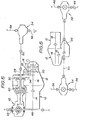
- Figs. 2 through 8 show modified embodiments of the present invention.
- the embodiment of Fig. 2 differs from the previous embodiment of Fig. 1 in that the speed-up mechanism 30 is connected to the ring gear 26 and the output shaft 28 in such a manner that the ring gear 26 and the output shaft 28 are driven to rotate in the same direction.
- the shaft 40 is integral with or fixedly mounted on the ring gear 26, while the internal gear 32 is fixedly mounted on the casing of the transaxle 12.
- the direction of revolution of the engine 10 is reverse to that of the previous embodiment of Fig. 1.
- this embodiment is substantially similar to the previous embodiment.
- the sun gear 34 is driven to rotate in the same direction as that of the ring gear 26 and at a speed higher than that of same, whereby engines which are different in the direction of revolution can be incorporated in the drive system in the same way.
- the embodiment of Fig. 3 differs from the previous embodiment of Fig. 1 or 2 in that the engine 10 and the transaxle 12 are horizontally rotatively displaced 180° relative to those of the previous embodiment of Fig. 1 or 2, that is, the engine 10 is installed on the forward part of the vehicle body and the transaxle 12 is installed rearwardly of the engine 10.
- This kind of modification in layout of the drive system becomes possible according to the present invention since the connection of the speed-up mechanism 30 relative to the ring gear 26 and the output shaft 28 can be changed to select a desired direction of rotation of the output shaft 28. Accordingly, it becomes possible to install the engine 10 on either of the forward part and rearward part of the vehicle, whereby to make it possible to reduce the design restrictions of the vehicle.
- Fig. 4 differs from the previous embodiment of Fig. 1 in that a center differential 60 in the form of a planetary gear train is additionally incorporated to attain full-time four wheel drive.
- Fig. 5 differs from the previous embodiment of Fig. 3 in that a center differential 60 in the form of a planetary gear train is additionally incorporated to attain full-time four wheel drive.
- Fig. 6 is adapted for midship mounting of the engine 10 on a four wheel drive vehicle such as a one-box car.
- Fig. 7 is adapted for use in a rear wheel drive vehicle of a midship engine. From this, it is to be noted that the present invention can be applied not only to a four wheel drive vehicle but to a two wheel drive vehicle.
- Fig. 8 is adapted for use in a rear wheel drive vehicle such as a one-box car.
Landscapes
- Engineering & Computer Science (AREA)
- Chemical & Material Sciences (AREA)
- Combustion & Propulsion (AREA)
- Transportation (AREA)
- Mechanical Engineering (AREA)
- Arrangement And Driving Of Transmission Devices (AREA)
- Arrangement Of Transmissions (AREA)
- Structure Of Transmissions (AREA)
- Retarders (AREA)
Applications Claiming Priority (2)
| Application Number | Priority Date | Filing Date | Title |
|---|---|---|---|
| JP265472/84 | 1984-12-18 | ||
| JP59265472A JPS61143227A (ja) | 1984-12-18 | 1984-12-18 | 車両駆動装置 |
Publications (2)
| Publication Number | Publication Date |
|---|---|
| EP0186123A2 true EP0186123A2 (fr) | 1986-07-02 |
| EP0186123A3 EP0186123A3 (fr) | 1987-01-21 |
Family
ID=17417641
Family Applications (1)
| Application Number | Title | Priority Date | Filing Date |
|---|---|---|---|
| EP85116174A Withdrawn EP0186123A3 (fr) | 1984-12-18 | 1985-12-18 | Système d'entraínement pour véhicule |
Country Status (2)
| Country | Link |
|---|---|
| EP (1) | EP0186123A3 (fr) |
| JP (1) | JPS61143227A (fr) |
Cited By (8)
| Publication number | Priority date | Publication date | Assignee | Title |
|---|---|---|---|---|
| FR2603529A1 (fr) * | 1986-09-10 | 1988-03-11 | Peugeot | Groupe motopropulseur pour vehicule automobile notamment a quatre roues motrices ou le moteur occupe une position centrale |
| EP0298397A3 (en) * | 1987-07-04 | 1989-04-26 | Bayerische Motoren Werke Ag | Motor vehicle drive arrangement |
| DE3911118A1 (de) * | 1988-04-21 | 1989-11-02 | Volkswagen Ag | Allradantrieb |
| EP0386922A1 (fr) * | 1989-02-28 | 1990-09-12 | Fuji Jukogyo Kabushiki Kaisha | Système pour contrôler un distributeur de couple destiné à un véhicule entraîné par quatre roues |
| EP1057675A3 (fr) * | 1999-06-01 | 2003-01-02 | Bayerische Motoren Werke Aktiengesellschaft | Boíte de vitesses pour véhicule à moteur centrale |
| DE102004002186A1 (de) * | 2004-01-15 | 2005-08-04 | Zf Friedrichshafen Ag | Antriebsstrang eines Allradfahrzeuges |
| CN100384678C (zh) * | 2005-01-14 | 2008-04-30 | 吴修登 | 沙漠越野卡丁车 |
| DE102008059979A1 (de) * | 2008-12-02 | 2010-06-10 | Magna Powertrain Ag & Co Kg | Sperrbare Differentialgetriebeeinheit |
Families Citing this family (3)
| Publication number | Priority date | Publication date | Assignee | Title |
|---|---|---|---|---|
| JPH0624266Y2 (ja) * | 1986-02-14 | 1994-06-29 | 株式会社神崎高級工機製作所 | 前後輪間のセンタ−デフ装置 |
| JPH11127545A (ja) | 1997-10-23 | 1999-05-11 | Nippon Seiki Co Ltd | 車両用計器装置 |
| JP4518032B2 (ja) * | 2006-03-16 | 2010-08-04 | トヨタ自動車株式会社 | 車両用動力伝達装置 |
Family Cites Families (7)
| Publication number | Priority date | Publication date | Assignee | Title |
|---|---|---|---|---|
| US2072380A (en) * | 1935-03-23 | 1937-03-02 | Chrysler Corp | Power driving device |
| GB536503A (en) * | 1940-03-15 | 1941-05-16 | Singer Motors Ltd | Improvements relating to change-speed mechanism |
| US3709314A (en) * | 1970-10-16 | 1973-01-09 | Fmc Corp | All terrain vehicle |
| GB2035930A (en) * | 1978-10-17 | 1980-06-25 | British Leyland Cars Ltd | Four-wheel drive transmissions |
| GB2116268B (en) * | 1982-03-11 | 1985-09-25 | Massey Ferguson Services Nv | Planetary gear overdrive or underdrive assemblies |
| JPS5938134A (ja) * | 1982-07-24 | 1984-03-01 | Honda Motor Co Ltd | 4輪駆動装置 |
| JPS6194822A (ja) * | 1984-10-16 | 1986-05-13 | Toyota Motor Corp | 四輪駆動車用動力伝達装置 |
-
1984
- 1984-12-18 JP JP59265472A patent/JPS61143227A/ja active Pending
-
1985
- 1985-12-18 EP EP85116174A patent/EP0186123A3/fr not_active Withdrawn
Cited By (9)
| Publication number | Priority date | Publication date | Assignee | Title |
|---|---|---|---|---|
| FR2603529A1 (fr) * | 1986-09-10 | 1988-03-11 | Peugeot | Groupe motopropulseur pour vehicule automobile notamment a quatre roues motrices ou le moteur occupe une position centrale |
| EP0298397A3 (en) * | 1987-07-04 | 1989-04-26 | Bayerische Motoren Werke Ag | Motor vehicle drive arrangement |
| DE3911118A1 (de) * | 1988-04-21 | 1989-11-02 | Volkswagen Ag | Allradantrieb |
| DE3911118C2 (de) * | 1988-04-21 | 1998-12-17 | Volkswagen Ag | Allradantrieb |
| EP0386922A1 (fr) * | 1989-02-28 | 1990-09-12 | Fuji Jukogyo Kabushiki Kaisha | Système pour contrôler un distributeur de couple destiné à un véhicule entraîné par quatre roues |
| EP1057675A3 (fr) * | 1999-06-01 | 2003-01-02 | Bayerische Motoren Werke Aktiengesellschaft | Boíte de vitesses pour véhicule à moteur centrale |
| DE102004002186A1 (de) * | 2004-01-15 | 2005-08-04 | Zf Friedrichshafen Ag | Antriebsstrang eines Allradfahrzeuges |
| CN100384678C (zh) * | 2005-01-14 | 2008-04-30 | 吴修登 | 沙漠越野卡丁车 |
| DE102008059979A1 (de) * | 2008-12-02 | 2010-06-10 | Magna Powertrain Ag & Co Kg | Sperrbare Differentialgetriebeeinheit |
Also Published As
| Publication number | Publication date |
|---|---|
| EP0186123A3 (fr) | 1987-01-21 |
| JPS61143227A (ja) | 1986-06-30 |
Similar Documents
| Publication | Publication Date | Title |
|---|---|---|
| US5950750A (en) | Drive arrangement for a motor vehicle | |
| US4998591A (en) | Electro-mechanical drive system for a full-track vehicle | |
| US4693334A (en) | Four wheel drive system | |
| US4650202A (en) | Power transmission for four-wheel drive vehicle | |
| US6719660B2 (en) | Power train assembly | |
| USRE32565E (en) | Four-wheel vehicle drive system | |
| JPS6157210B2 (fr) | ||
| JPS57186522A (en) | 4-wheel driven car | |
| US5078229A (en) | Four-wheel-drive motor vehicle of transversely-disposed engine type | |
| JPH0240896B2 (fr) | ||
| AU2001282320A1 (en) | Power train | |
| JPH07502097A (ja) | 差動装置 | |
| DE60127688D1 (de) | Leistungsübertragungsvorrichtung für kraftfahrzeug | |
| EP0327032A2 (fr) | Dispositif de transmission à différentiel avec une transmission planétaire réductrice du type à engainage interne | |
| CA1218539A (fr) | Mecanisme d'entrainement des roues avant et arriere d'un vehicule automobile | |
| EP0469128A1 (fr) | Boite de vitesses pour vehicules a moteur. | |
| US4450734A (en) | Transmission apparatus for a four-wheel drive motor vehicle | |
| JPS61143227A (ja) | 車両駆動装置 | |
| US4580459A (en) | Change-speed gear in group-type construction | |
| CA1210962A (fr) | Voiture a traction toutes roues | |
| US6001043A (en) | Drive mechanism for four wheel drive automobiles | |
| US7578762B2 (en) | Four-wheel drive vehicle transmission | |
| EP0442446B1 (fr) | Transmission à quatre roues motrices pour véhicule | |
| US4631978A (en) | Device for the distribution of motive power | |
| KR100204961B1 (ko) | 자동차용 4륜 구동 동력전달장치 |
Legal Events
| Date | Code | Title | Description |
|---|---|---|---|
| PUAI | Public reference made under article 153(3) epc to a published international application that has entered the european phase |
Free format text: ORIGINAL CODE: 0009012 |
|
| 17P | Request for examination filed |
Effective date: 19851219 |
|
| AK | Designated contracting states |
Kind code of ref document: A2 Designated state(s): DE FR GB |
|
| PUAL | Search report despatched |
Free format text: ORIGINAL CODE: 0009013 |
|
| AK | Designated contracting states |
Kind code of ref document: A3 Designated state(s): DE FR GB |
|
| STAA | Information on the status of an ep patent application or granted ep patent |
Free format text: STATUS: THE APPLICATION HAS BEEN WITHDRAWN |
|
| 18W | Application withdrawn |
Withdrawal date: 19871112 |
|
| RIN1 | Information on inventor provided before grant (corrected) |
Inventor name: TAKAHASHI, KOTEI |