EP0186143A2 - Appareil pour appliquer des feuilles de revêtement sur des éléments en forme de plaques ou analogues - Google Patents
Appareil pour appliquer des feuilles de revêtement sur des éléments en forme de plaques ou analogues Download PDFInfo
- Publication number
- EP0186143A2 EP0186143A2 EP85116275A EP85116275A EP0186143A2 EP 0186143 A2 EP0186143 A2 EP 0186143A2 EP 85116275 A EP85116275 A EP 85116275A EP 85116275 A EP85116275 A EP 85116275A EP 0186143 A2 EP0186143 A2 EP 0186143A2
- Authority
- EP
- European Patent Office
- Prior art keywords
- workpiece
- turntable
- holding table
- arrangement
- rotary table
- Prior art date
- Legal status (The legal status is an assumption and is not a legal conclusion. Google has not performed a legal analysis and makes no representation as to the accuracy of the status listed.)
- Withdrawn
Links
Images


Classifications
-
- B—PERFORMING OPERATIONS; TRANSPORTING
- B29—WORKING OF PLASTICS; WORKING OF SUBSTANCES IN A PLASTIC STATE IN GENERAL
- B29C—SHAPING OR JOINING OF PLASTICS; SHAPING OF MATERIAL IN A PLASTIC STATE, NOT OTHERWISE PROVIDED FOR; AFTER-TREATMENT OF THE SHAPED PRODUCTS, e.g. REPAIRING
- B29C63/00—Lining or sheathing, i.e. applying preformed layers or sheathings of plastics; Apparatus therefor
- B29C63/02—Lining or sheathing, i.e. applying preformed layers or sheathings of plastics; Apparatus therefor using sheet or web-like material
- B29C63/04—Lining or sheathing, i.e. applying preformed layers or sheathings of plastics; Apparatus therefor using sheet or web-like material by folding, winding, bending or the like
-
- B—PERFORMING OPERATIONS; TRANSPORTING
- B23—MACHINE TOOLS; METAL-WORKING NOT OTHERWISE PROVIDED FOR
- B23Q—DETAILS, COMPONENTS, OR ACCESSORIES FOR MACHINE TOOLS, e.g. ARRANGEMENTS FOR COPYING OR CONTROLLING; MACHINE TOOLS IN GENERAL CHARACTERISED BY THE CONSTRUCTION OF PARTICULAR DETAILS OR COMPONENTS; COMBINATIONS OR ASSOCIATIONS OF METAL-WORKING MACHINES, NOT DIRECTED TO A PARTICULAR RESULT
- B23Q7/00—Arrangements for handling work specially combined with or arranged in, or specially adapted for use in connection with, machine tools, e.g. for conveying, loading, positioning, discharging, sorting
- B23Q7/16—Loading work on to conveyors; Arranging work on conveyors, e.g. varying spacing between individual workpieces
- B23Q7/165—Turning devices
-
- B—PERFORMING OPERATIONS; TRANSPORTING
- B29—WORKING OF PLASTICS; WORKING OF SUBSTANCES IN A PLASTIC STATE IN GENERAL
- B29L—INDEXING SCHEME ASSOCIATED WITH SUBCLASS B29C, RELATING TO PARTICULAR ARTICLES
- B29L2031/00—Other particular articles
- B29L2031/44—Furniture or parts thereof
- B29L2031/448—Tables
Definitions
- the invention relates to a device for applying cover sheet material on carrier surfaces and in particular on main surfaces of plate-shaped workpieces, such as doors, table tops or the like, as well as on surfaces of other types of objects, in which the cover film material runs around a rounded edge that adjoins the carrier surface.
- the cover film material is first applied to the flat main surface in the usual way.
- the workpiece is then further processed in a device of the type described in the present application, to which the invention is directed.
- the workpiece is clamped and then a device for pressing the cover sheet material against the rounded edges of the work piece put into operation.
- This device can have a pressure bar arrangement with which the cover film material is bent around the rounded edge and at the same time the connection of the cover film material to the plate edge is effected.
- Such a device generally has a fixed, although optionally adjustable holding table for holding the workpieces, at least in their edge region.
- the workpieces are clamped to the holding table by means of a clamping device before the pressure bar arrangement is put into operation. If two, three or more edges of the same plate eckfolienmaterial to be coated with D in the same manner as the workpiece after coating the first edge is taken out from the apparatus, rotated and re-introduced into the device in the new position and clamped therein, after which the next coating can be done. This process is repeated until all edges are coated.
- the invention has for its object to improve a device of this type such that this process and thus the presentation of the edges to be treated in such a device ver is simplified, in particular if a number of edges, in particular but not exclusively those which comprise the entire circumference of a plate, are to be provided with cover film material which extends around the rounded edges of the workpiece.
- a device for applying D eckfolienmaterial like to the surface of plate-shaped workpieces which is characterized by a supporting table and cooperating with said clamping device, means to urge the cover sheet material on a rounded edge of the plate-shaped workpiece, which is clamped by the holding table and the clamping device, a turntable for holding the workpiece to be clamped in a position between the holding table and the clamping device and for rotating the workpiece substantially in the plane of the workpiece between selected angular positions, and by a device around the holding table and to keep the clamping device free of the workpiece held by the turntable during its rotation.
- the device with which the cover film material is pressed onto a rounded edge of the plate-shaped workpiece can be designed in various ways. It is advantageous if the device comprises a pressure bar arrangement.
- the Rotary table arranged on a carrier which is movable towards and away from the pressure bar arrangement. This not only simplifies the loading process, but also the positioning of the workpiece after each turning process.
- the carrier can be moved in a variety of ways. It is advantageous to provide a crank arrangement for this purpose, the stroke of which is adjustable.
- the device for keeping the workpiece free during the rotary movement can be designed in various ways. For example, it is possible to lower the holding table. A particularly expedient construction results, however, if the device for keeping the workpiece free during the rotary movement comprises a lifting arrangement with which the rotary table can be moved vertically. In this way, the workpiece can be raised relative to the holding table in order to carry out the rotary movement.
- the turntable is pressure-loaded in the direction of the raised position.
- This pressure load can take place, for example, via a spring or a pneumatic or hydraulic arrangement.
- the turntable is also raised automatically after the clamping device has been lifted, so that further control means are not required.
- the turntable can basically have any shape. Particularly advantageous, however, is when the turntable is dish-shaped and has a suction device which can be held with the workpiece during the D rehvorganges on the rotary table and fixed.
- the turntable does not have to be driven.
- the holding table can have a series of removable spacers which extend over its entire length. Because of this configuration, contamination of the holding table by glue or adhesive can be avoided, since it is possible to remove the spacer elements at those points where edges of the workpiece that carry glue or adhesive come to rest.
- holders for one or more glue application devices on the device can also be designed in the form of guide rails, as a result of which the glue application devices can be brought into adjustable positions on the device by reciprocating movement.
- a marking arrangement can be assigned to the turntable in order to be able to hold or stop the turntable in predetermined angular positions.
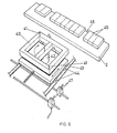
- the device comprises a frame 1 which carries a holding table 2 and above it a clamping device 3 which can be actuated by means of pneumatic cylinders 4.
- a device 5 for pressing the cover sheet material which device has a pressure bar fastened to arms 6 (see FIG. 2), which are held by rotatable brackets 7, so that the pressure bar arrangement and the arms carrying it (the are pivotally attached to their ends facing away from the pressure bar arrangement) can be moved by means of pneumatic cylinders 8 in order to keep the pressure bar arrangement in firm contact with the cover film material 9, which is applied to the rounded edge 10 of a plate 11 along the entire length of the pressure bar arrangement.
- the pressure bar arrangement can be heated, for example, by a heating element, not shown. Further details of this type of device can be found in the already mentioned South African patent application No. 84/3228.
- a turntable 12 and a support 13 holding it are movable on transverse guides 14 in a direction which is at right angles to the longitudinal direction of the clamping device 3.
- the carrier 13 is movably guided between an inner position in which it lies at least partially under the clamping device and outer positions in which it is distant therefrom.
- the guides are expediently designed with a circular cross section and have frame elements 15 directed outwards for their mounting.
- the carrier itself is held on the guides with the aid of sliding blocks 16 fastened to the carrier.
- the turntable and its support are movable along the guides by means of a cylinder arrangement 17 which is held by a frame arrangement 18 at the end remote from the clamping device.
- the movement of the carrier is limited by adjustable stops 19 which lie on a rod 20 which is movable together with the carrier.
- the stops 19 work together with a frame element 21 which is located at the opposite end of the clamping device.
- the stops expediently consist of simple screw nut arrangements and the rod is provided with a thread.
- the turntable can lift a plate-shaped workpiece held by it during operation so that it comes free from the holding table, the ends 22 of the outwardly directed frame elements 15 are covered by a section 23 of the main frame of the front direction held by compression springs 24.
- the compression springs load the entire support and guide arrangement in the direction of the raised position, so that when the clamping device is out of contact with the holding table 2, each workpiece held by the turntable is raised with respect to the holding table. If the clamping takes place, the turntable is automatically pressed down against the load by the springs, so that the workpiece is clamped firmly between the holding table 2 and the clamping device 3.
- the turntable and its support are located in an intermediate space in the longitudinal center of the holding table, which is most clearly shown in FIGS. 3 and 4.
- the turntable preferably has a circular shape and carries a sealing ring 25 on its circumference, a plate-shaped configuration being provided so that the central opening can be used for the application of a vacuum in order to hold a workpiece by means of the vacuum as desired on the turntable.
- a concentric gear 27 is provided immediately below it, which is in engagement with a drive gear 28, which is also arranged on the carrier and is driven by a pneumatic motor gear arrangement 29.
- the gear ratio is such that the drive gear 28 turns once for every 180 ° rotation of the turntable. In most cases they will be rectangular or Square workpieces in the form of plates coated with cover film material and accordingly the plate must be rotated by 90 ° if all edges are to be covered by the pressure bar arrangement.
- a microswitch assembly 30 cooperates with the drive gear 28 to detect every 180 ° rotation thereof, which corresponds to a 90 ° rotation of the turntable.
- the microswitch arrangement is connected in such a way that it actuates a pneumatic cylinder arrangement 31, shown in FIG.
- the microswitch arrangement actuates the pneumatic cylinder 31 together with its locking pin shortly before the full 180 ° rotation of the gearwheel has been carried out snaps into the correct position with the required opening.
- a plate can easily be arranged on the turntable in such a way that a plate edge lies in the desired position for the application of cover sheet material around a rounded plate edge.
- the cover film material has already been pressed onto the main surface of the plate in the usual way - as described at the beginning)
- the first edge can be treated using the pressure bar arrangement.
- the plate is raised due to the action of the compression springs 24 and the pneumatic motor gear arrangement 29 is actuated automatically and the turntable is rotated.
- the piston arrangement 17, which is also designed as a pneumatic arrangement and which controls the movement of the carrier, is actuated and the movement of the carrier is stopped by the engagement of the stops 19 on the frame element 21, through which the rod 20 carrying the stops passes.
- the drive gear 28 is rotatable together with a drive shaft 33 and a plate 34.
- the plate 34 is one in the longitudinal direction adjustable crank rod 35 screwed, which is pivotally connected at its free end 36 to the frame of the device and on which a further crank rod 38 is pivotably connected by means of a pivot pin 37 and is fastened to the carrier with its other end 39.
- the turntable can consist of a simple rectangular frame 40 and, in predetermined positions, have simple pins 41 for positioning workpieces.
- the turntable can be raised by means of a pneumatic or hydraulic cylinder arrangement 42, which extends between the turntable and a carrier 43 for the latter, and the carrier 43 can be mounted on rollers or other wheel arrangements 44.
- the adhesives intended for application to a plate, which are used to apply cover film material to the Workpiece should enable, are expediently essentially dry and therefore do not stick to the holding table and the clamping device.
- adhesives are used which are problematic in this regard, it is advantageous to provide a series of spacer elements, preferably in the form of holding blocks, which form the upper effective surface of the holding table 2 and - as indicated at 64 - can simply be removed, where at Operation of the device glue areas to be applied to the workpiece.
- glue flushing devices 47 are provided in the device in order to automatically apply adhesive to the required areas.
- the cover film material can be applied to all four edges, for example to form a desk top or a table top.
- the cover film material must be trimmed at its corners according to a correct pattern, which corresponds to the development of the connecting line of adjacent rounded edges.
- the edges can remain in the unprocessed state, but they can also be cut out and contain preformed or prefabricated inserts so that the corners have a smoother appearance.
Landscapes
- Engineering & Computer Science (AREA)
- Manufacturing & Machinery (AREA)
- Mechanical Engineering (AREA)
- Lining Or Joining Of Plastics Or The Like (AREA)
- Automatic Assembly (AREA)
- Coating Apparatus (AREA)
Applications Claiming Priority (2)
| Application Number | Priority Date | Filing Date | Title |
|---|---|---|---|
| ZA8410107 | 1984-12-28 | ||
| ZA8410107 | 1984-12-28 |
Publications (2)
| Publication Number | Publication Date |
|---|---|
| EP0186143A2 true EP0186143A2 (fr) | 1986-07-02 |
| EP0186143A3 EP0186143A3 (fr) | 1987-04-15 |
Family
ID=25577669
Family Applications (1)
| Application Number | Title | Priority Date | Filing Date |
|---|---|---|---|
| EP85116275A Withdrawn EP0186143A3 (fr) | 1984-12-28 | 1985-12-19 | Appareil pour appliquer des feuilles de revêtement sur des éléments en forme de plaques ou analogues |
Country Status (3)
| Country | Link |
|---|---|
| US (1) | US4741797A (fr) |
| EP (1) | EP0186143A3 (fr) |
| JP (1) | JPS61249232A (fr) |
Families Citing this family (7)
| Publication number | Priority date | Publication date | Assignee | Title |
|---|---|---|---|---|
| US5238515A (en) * | 1991-11-07 | 1993-08-24 | Haworth, Inc. | Fabric securement method |
| US5716494A (en) * | 1992-06-22 | 1998-02-10 | Matsushita Electric Industrial Co., Ltd. | Dry etching method, chemical vapor deposition method, and apparatus for processing semiconductor substrate |
| US6331223B1 (en) | 1997-12-24 | 2001-12-18 | Saint-Gobain Bayform America, Inc. | Method of fabricating adhesively secured frame assembly |
| US6279644B1 (en) | 1997-12-24 | 2001-08-28 | St. Gobain Bayform America Inc. | Screen and frame assembly in which the screen is adhesively secured to the frame |
| US6991693B2 (en) * | 1997-12-24 | 2006-01-31 | Saint-Gobain Bayform America, Inc. | Screen cloth insertion apparatus and method |
| US6977021B2 (en) * | 2003-07-09 | 2005-12-20 | Alumaroll Specialty Co., Inc. | Screen assembly and method |
| CN106002826B (zh) * | 2016-07-11 | 2018-04-10 | 京东方科技集团股份有限公司 | 灯条组装装置以及利用其进行灯条组装的方法 |
Family Cites Families (16)
| Publication number | Priority date | Publication date | Assignee | Title |
|---|---|---|---|---|
| US2576121A (en) * | 1949-04-19 | 1951-11-27 | Jacob S Kamborian | Method of applying flexible covering material to a relatively rigid backing |
| US2937689A (en) * | 1957-02-08 | 1960-05-24 | Uniflex Engineering Inc | Material bending apparatus |
| CH564987A5 (en) * | 1973-09-07 | 1975-08-15 | Beyeler Renee Louise | Numerically controlled metal shearing machine - has suction device below work table to manoeuvre plate to desired position |
| US4123311A (en) * | 1975-01-23 | 1978-10-31 | Mac Engineering & Equipment Company, Inc. | Machine for wrapping battery plates |
| US4022087A (en) * | 1976-03-02 | 1977-05-10 | Sidlaw Industries Limited | Method of and apparatus for cutting sheet material |
| US4035224A (en) * | 1976-04-08 | 1977-07-12 | The Shaw-Walker Company | Method and apparatus for forming a top assembly |
| US4220491A (en) * | 1978-10-19 | 1980-09-02 | Ppg Industries, Inc. | Method for forming an accurately assembled laminate utilizing a vacuum holding press |
| DE3003552C2 (de) * | 1980-01-31 | 1982-06-24 | Messerschmitt-Bölkow-Blohm GmbH, 8000 München | Flächenbauteil, insbesondere für ein Luftfahrzeug |
| US4530729A (en) * | 1981-06-05 | 1985-07-23 | Evana Tool & Engineering Inc. | Folding of flat sheet to exact interior height |
| US4478664A (en) * | 1981-11-04 | 1984-10-23 | Evans Rotork, Inc. | Round edge former |
| US4406729A (en) * | 1981-11-04 | 1983-09-27 | Evans Rotork, Inc. | Round edge former |
| DE3145661C2 (de) * | 1981-11-17 | 1984-11-29 | Anton Huber GmbH & Co, 8228 Freilassing | Vorrichtung zum Aufbringen eines überstehenden Randes eines Überzugmaterials |
| CA1227732A (fr) * | 1983-05-09 | 1987-10-06 | Pieter M. Henderson | Pose de pellicules decoratives a la surface du substrats |
| US4539066A (en) * | 1983-06-07 | 1985-09-03 | Henderson Pieter M | Application of surfacing sheets to panels, columns and the like |
| US4563233A (en) * | 1983-09-16 | 1986-01-07 | Karl-Heinz Schmitt | Application of surfacing sheet to panels, columns and the like |
| US4539005A (en) * | 1983-10-24 | 1985-09-03 | Greenblatt Gordon M | Blood infusion apparatus and method |
-
1985
- 1985-12-19 EP EP85116275A patent/EP0186143A3/fr not_active Withdrawn
- 1985-12-27 JP JP60299798A patent/JPS61249232A/ja active Pending
- 1985-12-30 US US06/814,689 patent/US4741797A/en not_active Expired - Fee Related
Also Published As
| Publication number | Publication date |
|---|---|
| US4741797A (en) | 1988-05-03 |
| JPS61249232A (ja) | 1986-11-06 |
| EP0186143A3 (fr) | 1987-04-15 |
Similar Documents
| Publication | Publication Date | Title |
|---|---|---|
| DE3605470C2 (fr) | ||
| DE1728496B2 (fr) | ||
| DE69000888T2 (de) | Verfahren und vorrichtung zum abschraegen von einspringenden ecken bei tafeln aus farbigem oder nicht farbigem flachglas. | |
| DE9114722U1 (de) | Rahmen zur Halterung von Zuschnitten für den Bezug von Formteilen | |
| CH447001A (de) | Vorrichtung zum Verschliessen von Behältern mittels einer Deckfolie | |
| DE2831763A1 (de) | Buchbindemaschine | |
| EP0292758A2 (fr) | Adaptateur pour serrer des vis à l'aide de tournevis motorisés | |
| DE3441198C2 (fr) | ||
| EP0704302A1 (fr) | Dispositif pour alimenter une plaque d'impression vers le cylindre porte-plaque d'une machine à imprimer | |
| EP0143257A1 (fr) | Raccordement d'outil d'une presse de découpage, notamment d'une presse de découpage à plateau revolver, pour le changement d'outil | |
| DE2134487C3 (de) | Rundschalttisch mit einem Schaltteller | |
| DE1291098B (de) | Vorrichtung zum Aufbringen von Umleimern aus Furnier oder Kunststoff | |
| EP0265589B1 (fr) | Presse de découpage | |
| DE3316518A1 (de) | Transportvorrichtung fuer plattenfoermige werkstuecke, wie moebelteile | |
| DE7537486U (de) | Revolverstanzpresse | |
| CH665159A5 (de) | Schleifmaschine. | |
| DE3219151A1 (de) | Spannvorrichtung | |
| CH687008A5 (de) | Biegevorrichtung fuer die Laengsdrahtenden von Bewehrungsgittern fuer Betonplatten. | |
| DD276840A1 (de) | Schneidemaschine zum beschneiden von papier, pappe od. dgl. mit einer schneidstation | |
| DE10059635A1 (de) | Kniehebelpresse | |
| EP0297471A2 (fr) | Procédé pour la commande d'un système de serrage | |
| DE69714997T2 (de) | Klebepresse | |
| DE9105405U1 (de) | Haltevorrichtung mit einer zum Festspannen eines Werkstücks vorgesehenen Schraubspindel | |
| DE1915587A1 (de) | Verfahren zum Verleimen eines Materialstreifens mit der Seite eines flachen Werkstuecks,wie ein Tischblatt,sowie eine Maschine zur Ausfuehrung dieses Verfahrens | |
| DE514364C (de) | Ziehpresse fuer Dosendeckel aus Celluloid o. dgl. |
Legal Events
| Date | Code | Title | Description |
|---|---|---|---|
| PUAI | Public reference made under article 153(3) epc to a published international application that has entered the european phase |
Free format text: ORIGINAL CODE: 0009012 |
|
| AK | Designated contracting states |
Kind code of ref document: A2 Designated state(s): AT DE FR GB IT |
|
| PUAL | Search report despatched |
Free format text: ORIGINAL CODE: 0009013 |
|
| AK | Designated contracting states |
Kind code of ref document: A3 Designated state(s): AT DE FR GB IT |
|
| 17P | Request for examination filed |
Effective date: 19870610 |
|
| 17Q | First examination report despatched |
Effective date: 19870929 |
|
| STAA | Information on the status of an ep patent application or granted ep patent |
Free format text: STATUS: THE APPLICATION IS DEEMED TO BE WITHDRAWN |
|
| 18D | Application deemed to be withdrawn |
Effective date: 19880210 |
|
| RIN1 | Information on inventor provided before grant (corrected) |
Inventor name: HENDERSON, PIETER MARTIN Inventor name: SCHMITT, KARL-HEINZ |