EP0186171A2 - Antriebsvorrichtung für einen Leistungsschalter - Google Patents
Antriebsvorrichtung für einen Leistungsschalter Download PDFInfo
- Publication number
- EP0186171A2 EP0186171A2 EP85116439A EP85116439A EP0186171A2 EP 0186171 A2 EP0186171 A2 EP 0186171A2 EP 85116439 A EP85116439 A EP 85116439A EP 85116439 A EP85116439 A EP 85116439A EP 0186171 A2 EP0186171 A2 EP 0186171A2
- Authority
- EP
- European Patent Office
- Prior art keywords
- closing
- spring
- latch
- shaft
- circuit breaker
- Prior art date
- Legal status (The legal status is an assumption and is not a legal conclusion. Google has not performed a legal analysis and makes no representation as to the accuracy of the status listed.)
- Ceased
Links
Images


Classifications
-
- H—ELECTRICITY
- H01—ELECTRIC ELEMENTS
- H01H—ELECTRIC SWITCHES; RELAYS; SELECTORS; EMERGENCY PROTECTIVE DEVICES
- H01H3/00—Mechanisms for operating contacts
- H01H3/22—Power arrangements internal to the switch for operating the driving mechanism
- H01H3/30—Power arrangements internal to the switch for operating the driving mechanism using spring motor
- H01H3/3042—Power arrangements internal to the switch for operating the driving mechanism using spring motor using a torsion spring
Definitions
- the invention relates to an operating device for circuit breakers according to the precharacterising part of claim 1.
- the operating device is primarily intended for metal-enclosed circuit breakers, insulated with sulphurhexafluoride (SF 6 ) gas, but it may be used for other types of circuit breakers as well.
- SF 6 sulphurhexafluoride
- puffer type SF 6 circuit breakers requires considerable operating energy. Since, in addition, short operating times are required, the movable parts of the operating device should be designed with as little a mass as possible. It is known to use for such operation pneumatic or hydraulic operating devices with pressurized gas as energy accumulator. However, such operating devices with associated compressors, pumps and other auxiliary equipment are relatively expensive. Normally, therefore, mechanical operating devices working without compressed air are preferred.
- the invention aims at developing an operating device of the above-mentioned kind which requires less space in the horizontal plane than comparable prior art designs and which is especially suitable for use for SF 6 circuit breakers with an earthed metal tank enclosure.
- the invention suggests an operating device for circuit breakers according to the introductory part of claim 1, which is characterized by the features of the characterizing part of claim 1.
- the operating device can advantageously be placed below the circuit breaker, which eliminates the need of special floor or ground space for the operating device.
- An exceedingly suitable embodiment of the invention is characterized in that both the opening spring and the closing spring of the operating device are of the spirally wound flat rod or ribbon type. With such springs an extremely compact embodiment of the operating device, in relation to its operating energy storing capacity, is achievable.
- the operating device shown in Figure 1 is built into a mechanism housing (not shown) and comprises an opening spring 1 and a closing spring 2. Both springs are of the spirally. wound flat rod or ribbon type, and each spring exerts a torsional moment on a corresponding shaft, namely, an operating shaft 3 and a driving shaft 4, respectively.
- the shafts 3 and 4 are aligned with each other, and their confronting ends are provided with a connection mechanism comprising a star wheel 6 fixed on the driving shaft 4 and a two-armed carrier 5 fixed on the operating shaft 3.
- One arm 51 of the carrier 5 supports a carrier latch 53 which cooperates with the star wheel 6, the second arm 52 being arranged to cooperate with an opening latch 7.
- the operating shaft 3 is connected to the circuit breaker by way of a lever 31 and a linkage (not shown).
- the opening spring 1 is tensioned and its shaft 3 hooked up on the opening latch 7.
- This position of the shaft which corresponds to the closed position of the circuit breaker, is shown in unbroken lines in Figure 1.
- the opening latch 7 is released, and the opening spring 1 rotates the shaft 3 so that the circuit breaker is opened.
- the operating shaft 3 operates back and forth between the two shown fixed positions.
- the closing spring 2 has its inner end fixed to the driving shaft 4 and its outer end fixed to a member 21 rotatable on the driving shaft 4, said member 21 suitably consisting of a wheel or a cylindrical drum surrounding the spring 2.
- the spring 2 can be tensioned by rotating the drum with the aid of a motor 22 via a suitable transmission means, for example a belt 23.
- the shaft is kept locked by a closing latch 8 which hooks up one of the arms of the star wheel 6. Closing of the circuit breaker takes place by releasing the closing latch 8, whereby another one of the arms of the star wheel 6 engages with the carrier latch 53 of the operating shaft 3 and rotates the latter through an angle corresponding to one step of the star wheel 6, which represents the movement of the entire operating shaft.
- the star wheel 6 may have two, three, four or more arms, depending on whether the operating shaft 3 with its spring 1 has been designed for a torsional angle of 180°, 120°, 90°, etc.
- Figure 2 shows functions of the torsional angle of the operating shaft 3 and for the three arms 61-63 of the star wheel 6 plotted against the time t during three successive closing and opening operations.
- the movement curve of the operating shaft 3 is drawn in unbroken line, whereas the curves for the arms 61, 62 and 63 are drawn in dashed, dash- dotted and double dotted dashed lines, respectively.
- the operating shaft 3 rotates back and forth between these two positions.
- the closing latch 8 Upon a closing operation, the closing latch 8 is released at the time t 1 .
- the device is ready to make an opening operation, which in the example shown is performed between times t 3 and t 4 .
- the drive motor 22 starts and tensions the closing spring, the device then being ready for the next closing operation. This time the arm 62 engages the carrier latch 53, and the procedure is repeated.
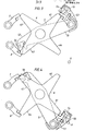
- Figures 3 and 4 show in more detail an embodiment of the connection mechanism between the two shafts 3, 4, namely, when the system (circuit breaker and operating device) is in the open position ( Figure 3), and when the system is in the closed position ( Figure 4).
- the star wheel 6 is provided with four arms 61-64, but otherwise this embodiment does not differ from the one shown in Figure 1.
- the carrier latch 5 and the opening latch 7 are positioned in a rear plane
- the star wheel 6, the closing latch 8 and the carrier latch 53 are positioned in an front plane.
- the latch means 7 and 8 consist of roller-type ratchets, which can be released by an opening and closing magnet, respectively (not shown).
- the carrier latch 53 consists of two cascade-connected roller-type ratchets 53, 54, which are released when a sliding surface 55 on the smaller latch 54 contacts the stationarily arranged disengaging projection 9.
- the free end portion of the carrier arm 52 is provided with a spring-loaded locking flap 56, which is arranged so that the arm 52 can pass freely past the opening latch 7 by the back way.
- Each one of the springs 1 and 2 may consist of a plurality of spiral spring elements arranged adjacent each other.
Landscapes
- Driving Mechanisms And Operating Circuits Of Arc-Extinguishing High-Tension Switches (AREA)
- Arrangement And Mounting Of Devices That Control Transmission Of Motive Force (AREA)
Applications Claiming Priority (2)
| Application Number | Priority Date | Filing Date | Title |
|---|---|---|---|
| SE8406647A SE449146B (sv) | 1984-12-28 | 1984-12-28 | Manoverdon for strombrytare |
| SE8406647 | 1984-12-28 |
Publications (2)
| Publication Number | Publication Date |
|---|---|
| EP0186171A2 true EP0186171A2 (de) | 1986-07-02 |
| EP0186171A3 EP0186171A3 (de) | 1988-12-21 |
Family
ID=20358329
Family Applications (1)
| Application Number | Title | Priority Date | Filing Date |
|---|---|---|---|
| EP85116439A Ceased EP0186171A3 (de) | 1984-12-28 | 1985-12-21 | Antriebsvorrichtung für einen Leistungsschalter |
Country Status (3)
| Country | Link |
|---|---|
| EP (1) | EP0186171A3 (de) |
| JP (1) | JPS61161628A (de) |
| SE (1) | SE449146B (de) |
Cited By (11)
| Publication number | Priority date | Publication date | Assignee | Title |
|---|---|---|---|---|
| US5448030A (en) * | 1992-08-07 | 1995-09-05 | Hitachi, Ltd. | Gas insulated circuit breaker |
| RU2110105C1 (ru) * | 1996-03-19 | 1998-04-27 | Российский Федеральный Ядерный Центр - Всероссийский Научно-Исследовательский Институт Экспериментальной Физики | Приводной механизм выключателя |
| RU2128379C1 (ru) * | 1996-02-27 | 1999-03-27 | Российский федеральный ядерный центр - Всероссийский НИИ. экспериментальной физики | Приводной механизм выключателя |
| FR2938692A1 (fr) * | 2008-11-20 | 2010-05-21 | Areva T & D Sa | Commande d'appareillage electrique haute ou moyenne tension a mecanisme a double accrochage ameliore et procede d'armement associe. |
| US8338732B2 (en) * | 2009-11-03 | 2012-12-25 | Abb Technology Ag | Spring operated actuator for an electrical switching apparatus |
| WO2014173732A1 (en) * | 2013-04-25 | 2014-10-30 | Siemens Aktiengesellschaft | Drive mechanism for circuit breaker |
| US20150364272A1 (en) * | 2013-03-08 | 2015-12-17 | Siemens Aktiengesellschaft | Switch, in particular power switch, for low voltages |
| GB2533372A (en) * | 2014-12-18 | 2016-06-22 | Eaton Ind (Netherlands) B V | Device for operating a switching device |
| US20170207038A1 (en) * | 2016-01-14 | 2017-07-20 | Hyundai Heavy Industries Co., Ltd. | Spring operation device of circuit breaker |
| GB2585835A (en) * | 2019-07-16 | 2021-01-27 | Eaton Intelligent Power Ltd | Relay |
| GB2605853A (en) * | 2021-04-15 | 2022-10-19 | Eaton Intelligent Power Ltd | Operating mechanism for a switch |
Families Citing this family (1)
| Publication number | Priority date | Publication date | Assignee | Title |
|---|---|---|---|---|
| CN104766730B (zh) * | 2014-11-17 | 2017-09-26 | 平高集团有限公司 | 高压开关及其机械操动机构 |
Family Cites Families (2)
| Publication number | Priority date | Publication date | Assignee | Title |
|---|---|---|---|---|
| CH208242A (de) * | 1939-01-07 | 1940-01-15 | Oerlikon Maschf | Einschaltvorrichtung für elektrische Schalter mit Spiralfeder als Kraftspeicher. |
| FR1378066A (fr) * | 1963-07-20 | 1964-11-13 | Merlin Gerin | Dispositif de commande à accumulation d'énergie, notamment pour interrupteurs électriques |
-
1984
- 1984-12-28 SE SE8406647A patent/SE449146B/sv not_active IP Right Cessation
-
1985
- 1985-12-21 EP EP85116439A patent/EP0186171A3/de not_active Ceased
- 1985-12-26 JP JP29964085A patent/JPS61161628A/ja active Pending
Cited By (19)
| Publication number | Priority date | Publication date | Assignee | Title |
|---|---|---|---|---|
| US5448030A (en) * | 1992-08-07 | 1995-09-05 | Hitachi, Ltd. | Gas insulated circuit breaker |
| RU2128379C1 (ru) * | 1996-02-27 | 1999-03-27 | Российский федеральный ядерный центр - Всероссийский НИИ. экспериментальной физики | Приводной механизм выключателя |
| RU2110105C1 (ru) * | 1996-03-19 | 1998-04-27 | Российский Федеральный Ядерный Центр - Всероссийский Научно-Исследовательский Институт Экспериментальной Физики | Приводной механизм выключателя |
| FR2938692A1 (fr) * | 2008-11-20 | 2010-05-21 | Areva T & D Sa | Commande d'appareillage electrique haute ou moyenne tension a mecanisme a double accrochage ameliore et procede d'armement associe. |
| EP2189995A2 (de) | 2008-11-20 | 2010-05-26 | Areva T&D Sas | Steuerung eines elektrischen Hoch- oder Mittelspannungsgerätes mit einem verbesserten doppelten Einrastmechanismus und entsprechendes Bestückungsverfahren |
| EP2189995A3 (de) * | 2008-11-20 | 2010-06-23 | Areva T&D Sas | Steuerung eines elektrischen Hoch- oder Mittelspannungsgerätes mit einem verbesserten doppelten Einrastmechanismus und entsprechendes Bestückungsverfahren |
| US8338732B2 (en) * | 2009-11-03 | 2012-12-25 | Abb Technology Ag | Spring operated actuator for an electrical switching apparatus |
| US20150364272A1 (en) * | 2013-03-08 | 2015-12-17 | Siemens Aktiengesellschaft | Switch, in particular power switch, for low voltages |
| US10147566B2 (en) * | 2013-03-08 | 2018-12-04 | Siemens Aktiengesellschaft | Switch, in particular power switch, for low voltages |
| WO2014173732A1 (en) * | 2013-04-25 | 2014-10-30 | Siemens Aktiengesellschaft | Drive mechanism for circuit breaker |
| GB2533372A (en) * | 2014-12-18 | 2016-06-22 | Eaton Ind (Netherlands) B V | Device for operating a switching device |
| US20170207038A1 (en) * | 2016-01-14 | 2017-07-20 | Hyundai Heavy Industries Co., Ltd. | Spring operation device of circuit breaker |
| CN106971900A (zh) * | 2016-01-14 | 2017-07-21 | 现代重工业株式会社 | 断路器的弹簧操作装置 |
| EP3200212A1 (de) * | 2016-01-14 | 2017-08-02 | Hyundai Heavy Industries Co., Ltd. | Federbetriebsvorrichtung eines schutzschalters |
| US10026567B2 (en) | 2016-01-14 | 2018-07-17 | Hyundai Electric & Energy Systems Co., Ltd. | Spring operation device of circuit breaker |
| GB2585835A (en) * | 2019-07-16 | 2021-01-27 | Eaton Intelligent Power Ltd | Relay |
| GB2585835B (en) * | 2019-07-16 | 2023-07-19 | Eaton Intelligent Power Ltd | Relay |
| US12033822B2 (en) | 2019-07-16 | 2024-07-09 | Eaton Intelligent Power Limited | Ultra-fast polarized relay for hybrid switching systems |
| GB2605853A (en) * | 2021-04-15 | 2022-10-19 | Eaton Intelligent Power Ltd | Operating mechanism for a switch |
Also Published As
| Publication number | Publication date |
|---|---|
| EP0186171A3 (de) | 1988-12-21 |
| SE8406647L (sv) | 1986-06-29 |
| SE8406647D0 (sv) | 1984-12-28 |
| JPS61161628A (ja) | 1986-07-22 |
| SE449146B (sv) | 1987-04-06 |
Similar Documents
| Publication | Publication Date | Title |
|---|---|---|
| EP0186171A2 (de) | Antriebsvorrichtung für einen Leistungsschalter | |
| US5280258A (en) | Spring-powered operator for a power circuit breaker | |
| US6610949B2 (en) | Switchgear operating apparatuses | |
| US4888458A (en) | Apparatus for disconnecting a switch of a high voltage electric circuit | |
| US5628394A (en) | Switchgear with top mounted vertical takeoff tripping and spring release interlock | |
| US4330960A (en) | Closing arrangement for sliding doors and the like | |
| CA1087662A (en) | Dual spring circuit interrupter apparatus | |
| CA2133059C (en) | Operating mechanism for circuit breaker | |
| CA2107817A1 (en) | Three-position switch actuating mechanism | |
| US4678877A (en) | Operating mechanism for a circuit-breaker, and a circuit-breaker fitted with the mechanism | |
| US20040262141A1 (en) | Spring-driven mechanism for rectilinear displacement circuit breaker | |
| US4578551A (en) | Operating mechanism for electrical switches | |
| JP3416086B2 (ja) | 開閉器の操作装置 | |
| US5107715A (en) | Circuit breaker drive mechanism | |
| WO2001071754A2 (en) | Stored energy system for breaker operating mechanism | |
| US6667452B2 (en) | High-voltage circuit-breaker having a spring-loaded control mechanism with an energy-recovering additional spring | |
| US4681993A (en) | Spring operating mechanism for an electrical switch | |
| EP1358663A1 (de) | Kompakter motorantrieb mit hoher geschwindigkeit für einen schutzschalter | |
| US5504293A (en) | Operating mechanism for electrical switches and fault interrupters | |
| CN1030966A (zh) | 零位闭锁力能量贮存装置 | |
| US4019008A (en) | Actuating mechanism for snap-actuating an electric switching apparatus | |
| US5909784A (en) | Spring motor | |
| EP0449148B1 (de) | Betätigungsvorrichtung für Schalter | |
| US3735779A (en) | Automatic controller drive mechanism | |
| US4761524A (en) | Switch operating mechanism |
Legal Events
| Date | Code | Title | Description |
|---|---|---|---|
| PUAI | Public reference made under article 153(3) epc to a published international application that has entered the european phase |
Free format text: ORIGINAL CODE: 0009012 |
|
| AK | Designated contracting states |
Kind code of ref document: A2 Designated state(s): CH DE FR GB IT LI NL |
|
| PUAL | Search report despatched |
Free format text: ORIGINAL CODE: 0009013 |
|
| AK | Designated contracting states |
Kind code of ref document: A3 Designated state(s): CH DE FR GB IT LI NL |
|
| 17P | Request for examination filed |
Effective date: 19890415 |
|
| 17Q | First examination report despatched |
Effective date: 19900628 |
|
| STAA | Information on the status of an ep patent application or granted ep patent |
Free format text: STATUS: THE APPLICATION HAS BEEN REFUSED |
|
| 18R | Application refused |
Effective date: 19920320 |
|
| RIN1 | Information on inventor provided before grant (corrected) |
Inventor name: EKWALL, OLLE Inventor name: SKOELD, LEIF |