EP0186221B1 - Procédé et système de commande pour freins d'avion - Google Patents
Procédé et système de commande pour freins d'avion Download PDFInfo
- Publication number
- EP0186221B1 EP0186221B1 EP85201303A EP85201303A EP0186221B1 EP 0186221 B1 EP0186221 B1 EP 0186221B1 EP 85201303 A EP85201303 A EP 85201303A EP 85201303 A EP85201303 A EP 85201303A EP 0186221 B1 EP0186221 B1 EP 0186221B1
- Authority
- EP
- European Patent Office
- Prior art keywords
- pressure
- metering valve
- port
- stage metering
- stage
- Prior art date
- Legal status (The legal status is an assumption and is not a legal conclusion. Google has not performed a legal analysis and makes no representation as to the accuracy of the status listed.)
- Expired
Links
- 238000000034 method Methods 0.000 title claims description 7
- 230000004044 response Effects 0.000 claims description 18
- 239000012530 fluid Substances 0.000 claims description 11
- 238000006073 displacement reaction Methods 0.000 claims description 4
- 230000008859 change Effects 0.000 claims description 2
- 230000000994 depressogenic effect Effects 0.000 claims description 2
- 238000013022 venting Methods 0.000 claims 3
- 230000000903 blocking effect Effects 0.000 claims 1
- 230000009467 reduction Effects 0.000 description 5
- 230000008901 benefit Effects 0.000 description 4
- 238000006243 chemical reaction Methods 0.000 description 4
- 238000007664 blowing Methods 0.000 description 3
- 238000004891 communication Methods 0.000 description 3
- 230000035945 sensitivity Effects 0.000 description 3
- 230000032258 transport Effects 0.000 description 3
- 230000009471 action Effects 0.000 description 2
- 230000000254 damaging effect Effects 0.000 description 2
- 230000001154 acute effect Effects 0.000 description 1
- 230000002411 adverse Effects 0.000 description 1
- 230000000712 assembly Effects 0.000 description 1
- 238000000429 assembly Methods 0.000 description 1
- 230000005540 biological transmission Effects 0.000 description 1
- 238000010276 construction Methods 0.000 description 1
- 230000036461 convulsion Effects 0.000 description 1
- 230000003247 decreasing effect Effects 0.000 description 1
- 238000010586 diagram Methods 0.000 description 1
- 230000000694 effects Effects 0.000 description 1
- ZZUFCTLCJUWOSV-UHFFFAOYSA-N furosemide Chemical compound C1=C(Cl)C(S(=O)(=O)N)=CC(C(O)=O)=C1NCC1=CC=CO1 ZZUFCTLCJUWOSV-UHFFFAOYSA-N 0.000 description 1
- 125000001145 hydrido group Chemical group *[H] 0.000 description 1
- 238000005096 rolling process Methods 0.000 description 1
Images

Classifications
-
- B—PERFORMING OPERATIONS; TRANSPORTING
- B60—VEHICLES IN GENERAL
- B60T—VEHICLE BRAKE CONTROL SYSTEMS OR PARTS THEREOF; BRAKE CONTROL SYSTEMS OR PARTS THEREOF, IN GENERAL; ARRANGEMENT OF BRAKING ELEMENTS ON VEHICLES IN GENERAL; PORTABLE DEVICES FOR PREVENTING UNWANTED MOVEMENT OF VEHICLES; VEHICLE MODIFICATIONS TO FACILITATE COOLING OF BRAKES
- B60T17/00—Component parts, details, or accessories of power brake systems not covered by groups B60T8/00, B60T13/00 or B60T15/00, or presenting other characteristic features
- B60T17/18—Safety devices; Monitoring
-
- B—PERFORMING OPERATIONS; TRANSPORTING
- B60—VEHICLES IN GENERAL
- B60T—VEHICLE BRAKE CONTROL SYSTEMS OR PARTS THEREOF; BRAKE CONTROL SYSTEMS OR PARTS THEREOF, IN GENERAL; ARRANGEMENT OF BRAKING ELEMENTS ON VEHICLES IN GENERAL; PORTABLE DEVICES FOR PREVENTING UNWANTED MOVEMENT OF VEHICLES; VEHICLE MODIFICATIONS TO FACILITATE COOLING OF BRAKES
- B60T8/00—Arrangements for adjusting wheel-braking force to meet varying vehicular or ground-surface conditions, e.g. limiting or varying distribution of braking force
- B60T8/32—Arrangements for adjusting wheel-braking force to meet varying vehicular or ground-surface conditions, e.g. limiting or varying distribution of braking force responsive to a speed condition, e.g. acceleration or deceleration
- B60T8/321—Arrangements for adjusting wheel-braking force to meet varying vehicular or ground-surface conditions, e.g. limiting or varying distribution of braking force responsive to a speed condition, e.g. acceleration or deceleration deceleration
- B60T8/325—Systems specially adapted for aircraft
-
- B—PERFORMING OPERATIONS; TRANSPORTING
- B60—VEHICLES IN GENERAL
- B60T—VEHICLE BRAKE CONTROL SYSTEMS OR PARTS THEREOF; BRAKE CONTROL SYSTEMS OR PARTS THEREOF, IN GENERAL; ARRANGEMENT OF BRAKING ELEMENTS ON VEHICLES IN GENERAL; PORTABLE DEVICES FOR PREVENTING UNWANTED MOVEMENT OF VEHICLES; VEHICLE MODIFICATIONS TO FACILITATE COOLING OF BRAKES
- B60T8/00—Arrangements for adjusting wheel-braking force to meet varying vehicular or ground-surface conditions, e.g. limiting or varying distribution of braking force
- B60T8/32—Arrangements for adjusting wheel-braking force to meet varying vehicular or ground-surface conditions, e.g. limiting or varying distribution of braking force responsive to a speed condition, e.g. acceleration or deceleration
- B60T8/34—Arrangements for adjusting wheel-braking force to meet varying vehicular or ground-surface conditions, e.g. limiting or varying distribution of braking force responsive to a speed condition, e.g. acceleration or deceleration having a fluid pressure regulator responsive to a speed condition
- B60T8/36—Arrangements for adjusting wheel-braking force to meet varying vehicular or ground-surface conditions, e.g. limiting or varying distribution of braking force responsive to a speed condition, e.g. acceleration or deceleration having a fluid pressure regulator responsive to a speed condition including a pilot valve responding to an electromagnetic force
- B60T8/3695—Arrangements for adjusting wheel-braking force to meet varying vehicular or ground-surface conditions, e.g. limiting or varying distribution of braking force responsive to a speed condition, e.g. acceleration or deceleration having a fluid pressure regulator responsive to a speed condition including a pilot valve responding to an electromagnetic force wherein the pilot valve is mounted separately from its power section
Definitions
- the present invention relates to an aircraft wheel brake controlling system as described in the preamble of claim 1, and to a method of using such a system.
- An aircract wheel brake controlling system as described in said preamble and as depicted in Fig. 1 is generally known.
- the pilot applied force which displaces the port control member of the valve becomes balanced in a closed loop fashion by the metered pressure which is developed as a result of flow through the valve to the brakes.
- the feedback pressure (which may also be termed the "brake metered pressure")
- the valve is driven back to its no flow or null position, against the pilot applied force, to achieve a condition of equilibrium.
- the pilot simply relaxes the applied force.
- the brake pressure feedback force then moves the port control member of the valve back to its off position in which it communicates the brake line with return pressure.
- a principal problem with this type of system is that a basic characteristic of aircraft brakes makes the initial application of braking quite difficult. This has been the source of numerous complaints by flight crews and is referred to by the general term of brake sensitivity. Brakes by their very nature must rotate as freely as possible when there is no brake pressure applied to them. This is necessary in order to minimize rolling drag resistance during takeoff and taxi operations which would otherwise reduce airplane takeoff performance and generate unnecessary brake heat. In order to minimize this drag, multi-rotor disk brakes are designed with considerable rotor- stator clearances. Springs are generally used to ensure that the brake pistons are retracted when there is no applied brake pressure.
- the braking metering valve in the conventional system delivers pressure to the brake through an antiskid valve. If the resulting wheel speed response characteristics due to the braking action are satisfactory, as sensed by a wheel speed transducer and interpreted by an antiskid control unit, the antiskid valve does not reduce or alter the brake pressure in any way. If, however, the wheel speed response indicates that there is adverse skidding due to excessive brake pressure, then, the control unit will send a signal to the antiskid valve sufficient to reduce the brake pressure until proper wheel speed response is regained.
- the pilot In the event of a failure of the antiskid system the pilot must be particularly careful since the only means in the conventional system for controlling the brake pressure is the brake metering valve which is connected to the full hydraulic system pressure source. In this antiskid off mode of operation, the pilot runs considerable risk of blowing tires if he applies to much brake force that he causes a wheel to lockup. On large aircraft it is very difficult to determine whether any of the several braked wheels are at or near the point of skidding in a braking condition with the antiskid system off or disabled.
- the brake control system of the present invention is basically characterized by a three stage metering valve system.
- the first stage is connected to a foot pedal controlled by the pilot.
- the pilot's use of his foot pedal meters pressure through this valve to a second stage metering valve.
- the second stage metering valve includes electrical control means for modulating the pressure delivered to it by the first stage valve.
- the second stage valve is controlled by an electrical input signal supplied by the pilot.
- This valve has an open position in which it transmits the output pressure of the first stage valve directly to a command pressure chamber of the third stage metering valve without change. This command pressure is used for positioning a port control member of the third stage valve.
- the third stage valve meters flow and pressure from a supply pressure to the wheel brakes.
- the metered pressure from the first stage valve is transmitted to the command pressure chamber of the third stage valve, and is used for moving the port control member of the third stage valve for metering pressure to the brakes.
- An electrical signal to the second stage metering valve causes a reduction in pressure between the second stage metering valve and the command pressure chamber of the first stage metering valve.
- the pressure in the command pressure chamber is fed back to the first stage metering valve and is used for exerting a force on the port control member of such valve in opposition to the pilot applied force, for moving such valve into a null position.
- the volume of the components between the output port of the said first stage metering valve and the command pressure chamber of the third stage metering valve is relatively small and is always substantially full of fluid. Accordingly, very little flow is required through the first stage metering valve in order to produce a feedback pressure that can be felt by the pilot. This makes the system very responsive, both when the second stage metering device is open and inoperative and when it is in use for reducing pressure to the command pressure chamber.
- the second stage metering valve is activated to benefit taxi braking and during times when the conventional antiskid control has either failed or is off.
- the pilot is faced with the difficulty of trying to gently apply braking with a system that is necessarily designed by and for high energy situations associated with aborted take-offs.
- a small pressure e.g. approximately 400 to 700 psi.
- the system of the present invention provides the capability to scale down the awkward large pressure by supplying a given value of control current and allows the same full range of brake pedal travel loads as used normally.
- a control current could be selected so that while the pressure output of the first stage valve is controlled from zero to 3,000 psi, the pressure from the second stage metering valve varies from say, zero to 900 psi.
- This pressure reduction in conjunction with the automatic brake pressure control of the third stage, can provide an extremely smooth taxi braking system.
- the system of the present invention has the ability by means of a pilot selected control current sent to the second stage metering valve to reduce the maximum brake pressure to a point where the possibility of blowing tires (due to locking up of the wheels) is either substantially reduced or eliminated.
- the control current might be set at a value that would keep the pressure that is delivered by the second stage metering valve to the command pressure chamber of the third stage metering valve somewhere between zero and 700 psi, while the pressure through the first stage metering valve is varied somewhere between zero and 3,000 psi. If the tire will not lock up and skid with 700 psi on the brake, then the landing can be made without concern of the damaging effects of a failed tire.
- the second stage metering valve if the second stage metering valve is not activated, it does very little to alter the pressure output of the first stage metering valve, so that the command pressure chamber of the third stage metering valve will receive the output pressure of the first stage metering valve.
- a closed loop control of the third stage metering valve which provides the pilot with a means whereby he has automatic brake pressure control in direct response to his mechanical foot pedal control force. This occurs as the third stage metering valve develops a brake operating pressure in response to the output pressure of the first stage metering valve.
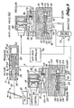
- the conventional system comprises a single stage metering valve 10 which includes a pressure port 12, a return port 14 and an output port 16.
- the ports are in a housing 18 which has an open end 20 and a closed end 22 and which defines an axial chamber 26.
- a valve port control member 24 is received within the axial chamber 26.
- Valve port control member 24 comprises a pair of axially spaced apart lands 28, 30 and an annular galley 32 positioned between the lands 28, 30. It also includes a feedback passageway 34 which connects the galley 32 with a feedback chamber 36 defined at the closed end of the housing 18.
- a pilot operated foot pedal 38 is connected to an outer control end portion of the member 24, by a system of cables and mechaincal linkages, or the like, designated 40 in Fig. 1.
- Fig. 1 shows valve 10 in its fully off position. In this position the land 30 blocks pressure port 12 and the output port 16 is in communication with the return pressure via galley 32 and return port 14.
- the port control member 24 is in an extended position and the foot pedal 38 is "up".
- a conduit 42 connects the output port 16 to an input port 44 of an antiskid valve 46.
- the port control member 48 of antiskid valve 46 is positioned to allow unmodulated feed of pressure and flow through the antiskid valve 46 to the piston of the brake 50.
- the brake port 52 of antiskid valve 46 is shown connected to a conduit 54 which leads to the brake pistons.
- the port control member 48 includes first and second axially spaced apart lands 56, 58, and an annular galley 62 positioned between them.
- a command pressure chamber 64 is defined at a first end of the port control member 48 and a feedback chamber 66 is defined at the opposite end.
- a command pressure in chamber 64 acts on surface 68 to urge port control member 48 towards a fully open position and the feedback pressure in chamber 66 acts on a surface 70 and tends to urge the port control member 48 in an opposite or flow and pressure reducing direction.
- a feedback passageway 72 communicates the galley 62 with the feedback chamber 66. When the galley 62 is in communication with the return port 74, the feedback chamber 66 in at return pressure. When the galley 62 is in communication with the brake port 52, the feedback chamber 66 receives the brake pressure.
- the conventional antiskid valve 46 that is illustrated includes a supply pressure port 76 which delivers fluid through a filter 78 to a first nozzles 80.
- Nozzle 80 is positioned to discharge into a chamber 82.
- a second nozzle 84 is positioned opposite nozzle 80.
- a flapper 86 is positioned between the nozzle 80, 84 and is moved back and forth by a torque motor 88. When the flapper 86 is in the position illustrated, the orifice of nozzle 84 is closed and the pressure delivered into chamber 82 is transmitted via a passageway 90, which includes a flow control orifice 92, into the command pressure chamber 64.
- the aircraft wheel W includes a transducer 94 which measures wheel speed.
- transducer 94 indicates that the wheel is not skidding, the antiskid valve 46 will not modulate the flow and pressure to the brake piston.
- the signal from transducer 94 is received by a controller 96. If this signal indicates that the brake force is too large, the controller 96 sends a signal to the torque motor 88, causing it to swing the flapper 86 away from nozzle 84 and towards nozzle 80. This results in the orifice in nozzle 84 being uncovered and being connected via passageway 98 to return port 74.
- the pressure within chamber 82 is reduced and this means that the command pressure delivered via passageway 90 to command pressure chamber 64 is also reduced.
- Antiskid valves of this general configuration are manufactured by a number of companies for a variety of applications in industry and especially in aerospace. Typical suppliers include: Hydraulics Research, Los Angeles, California; Goodyear Aerospace, Akron, Ohio; Dunlop, England; and Bendix, Los Angeles, California. The particular valve that is illustrated is a valve marketed by the Hydro Aire Division of the Crane Company, of Burbank, California, and has a Hydro Part Number of 37-231.
- the antiskid valve shown in Fig. 1 has been described in considerable detail, because the system of the present invention includes a second valve of this type which is located between the pedal controlled valve and the regular functioning antiskid valve 46, in a different hookup, to produce a new function.
- valve assembly identical to the valve assembly which performs the antiskid function is merely one way (a convenient way) of obtaining hardware capable of being combined with a conventional single stage metering valve 10 to provide the three stage metering valve which characterizes the control system of the present invention.
- a person skilled in the art could take the information set forth below and use it to construct a number of hardware embodiments, differing from the hardware that is disclosed but capable of performing the same function.
- the various units, assemblies and subassemblies utilized in the system can be divided and combined component-wise in a number of differnt ways. Each may include its own housing, or several or all of the components may be included in a single housing.
- the conventional single stage valve 10 is connected to a conventional antiskid valve 100 in a novel way, to produce what is in effect a three stage metering valve.
- the three stage metering valve replaces the old single stage valve in series between the brake pedal 38 and the antiskid valve 46.
- valve 100 of the illustrated embodiment is identical to the above-described antiskid valve 46, because it is plumbed into the system in a different way, to perform a different function, the valve 100 will be redescribed, using new reference numerals for each of its parts, so that these reference numerals can be used in a description of the new function formed by this admittedly old hardware.
- a first conduit 102 connects the output port 16 of valve 10 with inlet port 104 of valve 100. Fluid delivered via passageway 102 and port 104 flows through a filter 106 to a first nozzle 108.
- a second nozzle 110 is spaced opposite nozzle 108, and a flapper 112 is positioned between the two end orifices of the two nozzles 108, 110. Flapper 112 is positioned back and forth between the two orifices by a torque motor 114 which receives a command signal from a current control device 116 which receives its input from the pilot 118.
- the pressure reduction is substantially linear and is proportional to an electrical command signal.
- Nozzle 108 discharges into a chamber 120.
- a passageway 122 communicates chamber 120 with a command pressure chamber 124 at one end of a valve port control member 126.
- a flow control restriction or orifice 128 is located in passageway 122.
- Valve port control member 126 includes axially spaced apart lands 130, 132, separated by an annular galley 134. Port control member 126 controls fluid flow and pressure transmission between a pressure port 136 and an output port 138 and a return port 140. The output port 138 is connected via a fifth conduit 142 to the input port 44 of the antiskid valve 46. Valve port control member 126 includes a feedback passageway 144 which connects the galley 134 with a feedback chamber 146 defined in the valve housing at the end of member 126 opposite the command pressure chamber 124.
- valve 100 which includes the flapper 112 is herein referred to as the second stage metering valve.
- the valve unit 10 functions as a first stage metering valve and will hereinafter be referred to as the first stage metering valve 10.
- the portion of valve 100 which includes valve port control member 126 will be referred to as the third stage metering valve.
- the output port 16 of the valve 10 would be connected to the port which is designated 44 in Fig. 2. (see Fig. 1).
- the output port 16 of the first stage valve 10 is connected to the input port of nozzle 108.
- the input or pressure port 136 is connected to a source of supply pressure.
- the output port 138 of valve 100 is connected via the fifth conduit 142 to the inlet port 44 of the antiskid valve 46.
- Return port 140 is connected to return pressure.
- the port control member 24 When the pilot 118 applies a force to the first stage metering valve 10 through his foot pedal 38, the port control member 24 is moved to develop a pressure in path 16, 102, 104 which is in direct proportion to the applied force at the pedal 38.
- the volume of fluid between port 16 and nozzle 18 is very small.
- the response of pressure between port 16 and nozzle 108 is very rapid relative to the applied force. This means that the feedback pressure load to the pedal 38 also responds rapidly.
- the second stage valve 108, 110, 112 receives the pressure from port 16 and either transmits it on unchanged or reduces it in proportion to the control current from 116, to produce the command pressure in chamber 124. Again, the volume between chamber 120 and chamber 124 is very small and the response is therefore extremely rapid.
- the third stage of the metering valve receives the command pressure in chamber 124 and uses it to develop the pressure that is delivered by the third stage, via conduit 142, to the antiskid valve 46.
- the volume of fluid between port 138 and the brake piston is considerable since it consists of the hydraulic conduits leading to the brake and the brake volume itself. Due to the capacity of the third stage, however, and its automatic pressure and flow control characteristics, the third stage is capable of fillling the brakes and establishing a steady brake pressure much more quickly then is possible with the conventional system (Fig. 1) where a simple brake metering valve 10 is used alone.
- the pilot has direct control of the first stage through his brake pedal system 38, 40, 24.
- Fig. 2 also shows that the pilot can activate the second stage by means of the control current source 118.
- the third stage provides the desired output power in a controlled fashion to establish the desired level of braking.
- control current would be set to zero or switched off. This could also be the case for taxi braking since the third stage of the invention provides much improved braking characteristics on its own compared to existing systems.
- the complete thrre stage assembly would be active to reduce the output brake pressures consistant with antiskid failure performance requirements. In certain cases this type of control mode could also improve taxi braking characteristics beyond that mentioned above.
- this stage When the second stage is activated by means of a control current signal this stage is able to reduce or scale down pressure B (between chamber 120 and chamber 124) in a proportional manner relative to pressure A (between port 16 and nozzle 108).
- Pressure C (from port 138) which is sent to the brakes responds directly to pressure B by the action of the third stage, providing automatic control of the intended brake pressure.
- a reduction or ratio between pressure B and pressure A can be adjusted by varying the amount of valve control current, by use of the current control 116.
- variable gain three stage brake metering valve system The value of this mode of operation of the variable gain three stage brake metering valve system is specifically significant for two situations of airplane braking control. These are (1) taxi braking and (2) antiskid system failed/off dispatches.
- taxi braking requires a much smaller pressure (e.g. approximately 400 to 700 psi).
- This invention provides the capability to scale down the output pressure (pressure B relative to pressure A) by supplying a given value of control current and allows the same full range of brake pedal travel and loads as used normally. For instance, the control current could be selected so that when pressure A was controlled from zero to 3,000 psi, pressure B would vary from zero to 900 psi.
- This pressure reduction in conjunction with the automatic brake pressure control of the third stage, can provide an exceptionally smooth taxi braking system.
- the brake control system of the present invention has the ability by means of the control current sent to the second stage to reduce the maximum brake pressure to the point where the possibility of blowing tires (due to locking up the wheels) is either substantially reduced or eliminated.
- the control current might be set at a value that would keep pressure B between zero and 700 psi when pressure A varies from zero to 3,000 psi. If the tire will not lockup and skid with 700 psi on the brake, then the landing can be made without concern for the damaging effects of a failed tire.
- the second stage of the invention When the second stage of the invention is not activated, it does very little to alter the pressure sent out by the brake metering valve so that pressure A and pressure B are essentially equal.
- the addition of the closed loop control of the third stage provides the pilot with a means whereby he has automatic brake pressure control in direct response to his mechanical foot pedal control force. This occurs as the third stage develops pressure C in response to pressure B (where B equals A) sent by the first stage.
- the second stage is inactive during this mode of operation and the hydraulic fluid simply passes through this stage.
- the system of the present invention has the following advantages:
Landscapes
- Engineering & Computer Science (AREA)
- Transportation (AREA)
- Mechanical Engineering (AREA)
- Physics & Mathematics (AREA)
- Electromagnetism (AREA)
- Fluid Mechanics (AREA)
- Aviation & Aerospace Engineering (AREA)
- Regulating Braking Force (AREA)
Claims (11)
Applications Claiming Priority (2)
| Application Number | Priority Date | Filing Date | Title |
|---|---|---|---|
| US06/685,298 US4640475A (en) | 1984-12-24 | 1984-12-24 | Aircraft wheel brake control system and method |
| US685298 | 1984-12-24 |
Publications (3)
| Publication Number | Publication Date |
|---|---|
| EP0186221A2 EP0186221A2 (fr) | 1986-07-02 |
| EP0186221A3 EP0186221A3 (en) | 1988-10-05 |
| EP0186221B1 true EP0186221B1 (fr) | 1990-07-18 |
Family
ID=24751579
Family Applications (1)
| Application Number | Title | Priority Date | Filing Date |
|---|---|---|---|
| EP85201303A Expired EP0186221B1 (fr) | 1984-12-24 | 1985-08-09 | Procédé et système de commande pour freins d'avion |
Country Status (3)
| Country | Link |
|---|---|
| US (1) | US4640475A (fr) |
| EP (1) | EP0186221B1 (fr) |
| DE (1) | DE3578751D1 (fr) |
Families Citing this family (18)
| Publication number | Priority date | Publication date | Assignee | Title |
|---|---|---|---|---|
| US4923056A (en) * | 1989-02-21 | 1990-05-08 | Aircraft Braking Systems Corporation | Method of increasing the service life of aircraft carbon disk brakes |
| US5044697A (en) * | 1989-05-26 | 1991-09-03 | Crane Company | Brake valve control system |
| US4993781A (en) * | 1989-09-21 | 1991-02-19 | The Boeing Company | Antijam brake-metering valve and method for its use |
| US6604708B1 (en) * | 1989-12-26 | 2003-08-12 | The Boeing Company | Carbon brake wear for aircraft |
| ES2059118T3 (es) * | 1990-01-31 | 1994-11-01 | Grau Ltd | Sistema de frenos de vehiculo. |
| US5050940A (en) * | 1990-02-05 | 1991-09-24 | Allied-Signal Inc. | Brake control and anti-skid system |
| FR2702447B1 (fr) * | 1993-03-08 | 1995-04-28 | Messier Bugatti | Dispositif de freinage électro-hydraulique d'un train de roues d'aéronef. |
| US5411323A (en) * | 1993-03-17 | 1995-05-02 | Sumitomo Precision Products Co., Ltd. | Automatic brake control apparatus and a brake pressure control valve |
| FR2715484B1 (fr) * | 1994-01-21 | 1996-02-23 | Chateaudun Hydraulique | Servovalve de régulation de pression. |
| US6088646A (en) * | 1996-10-25 | 2000-07-11 | The Boeing Company | Fuzzy logic antiskid control system for aircraft |
| US6142585A (en) * | 1997-10-14 | 2000-11-07 | The Boeing Company | Antiskid/autobrake control system with low-speed brake release to reduce gear walk |
| US6241325B1 (en) | 1997-10-14 | 2001-06-05 | The Boeing Company | Low-speed antiskid control for multigain hydraulic valve brake system |
| FR2773530B1 (fr) * | 1998-01-12 | 2000-02-11 | Messier Bugatti | Dispositif de freinage d'un train de roues d'aeronef |
| US20060071547A1 (en) * | 2004-09-30 | 2006-04-06 | Eaton Corporation | Valve assembly for anti-skid aircraft brakes |
| DE102007032310A1 (de) * | 2007-07-11 | 2009-01-15 | Deere & Company, Moline | Bedienvorrichtung |
| WO2009089551A2 (fr) * | 2008-01-11 | 2009-07-16 | General Atomics | Système de freinage à actionneur linéaire |
| US9709177B2 (en) | 2015-01-13 | 2017-07-18 | Honeywell International Inc. | Two-position, two-stage servo valve |
| CN104890863B (zh) * | 2015-06-03 | 2017-12-12 | 西安航空制动科技有限公司 | 一种具有非减压直供能力的刹车阀 |
Family Cites Families (10)
| Publication number | Priority date | Publication date | Assignee | Title |
|---|---|---|---|---|
| US2826278A (en) * | 1954-04-20 | 1958-03-11 | Goodyear Tire & Rubber | Hydraulic apparatus for anti-skid or manual control of brakes with safety lockout of anti-skid control |
| US3443594A (en) * | 1966-11-21 | 1969-05-13 | Goodyear Tire & Rubber | Proportional pressure valve |
| US3671082A (en) * | 1970-03-04 | 1972-06-20 | Bertea Corp | Antiskid system |
| US3826541A (en) * | 1970-05-01 | 1974-07-30 | Toyota Motor Co Ltd | Vehicle brake systems using skid control devices |
| US4076331A (en) * | 1973-09-06 | 1978-02-28 | The Boeing Company | Aircraft automatic braking system |
| US4130322A (en) * | 1976-11-16 | 1978-12-19 | Crane Co. | Single gain skid control valve and skid control system |
| US4125234A (en) * | 1977-02-28 | 1978-11-14 | Tregre George W | Emergency circulating system for an aircraft hydraulic brake system |
| US4198102A (en) * | 1978-10-10 | 1980-04-15 | The Boeing Company | Automatic system pressure shut off valve for anti-skid control system |
| US4260198A (en) * | 1979-03-26 | 1981-04-07 | Crane Co. | Skid control valve and system |
| US4360239A (en) * | 1980-01-21 | 1982-11-23 | Mcdonnell Douglas Corporation | Manual/auto brake valve |
-
1984
- 1984-12-24 US US06/685,298 patent/US4640475A/en not_active Expired - Lifetime
-
1985
- 1985-08-09 EP EP85201303A patent/EP0186221B1/fr not_active Expired
- 1985-08-09 DE DE8585201303T patent/DE3578751D1/de not_active Expired - Lifetime
Also Published As
| Publication number | Publication date |
|---|---|
| US4640475A (en) | 1987-02-03 |
| DE3578751D1 (de) | 1990-08-23 |
| EP0186221A2 (fr) | 1986-07-02 |
| EP0186221A3 (en) | 1988-10-05 |
Similar Documents
| Publication | Publication Date | Title |
|---|---|---|
| EP0186221B1 (fr) | Procédé et système de commande pour freins d'avion | |
| US5024491A (en) | Automatic aircraft braking system including wheelspeed responsive control apparatus | |
| US4007970A (en) | Aircraft automatic braking system | |
| US3588192A (en) | Hydraulic skid control system | |
| US4120540A (en) | Aircraft automatic braking system | |
| JP3851779B2 (ja) | 二重冗長能動/能動ブレーキ・バイ・ワイヤ技術 | |
| US4755008A (en) | Braking system with power brake, braking force proportioning, anti-skid, and traction control functions | |
| JP3066755B2 (ja) | 車両のアンチロック・ブレーキ装置 | |
| US3544171A (en) | Anti-skid device for hydraulic brake system | |
| US5700067A (en) | Hydraulic braking system, especially for motor vehicles | |
| US3881783A (en) | Fixed slip hydraulic anti-lock braking system | |
| GB2107416A (en) | Anti-skid modulators in hydraulic braking systems | |
| CN110606195B (zh) | 一种飞机应急刹车系统及其设计方法 | |
| EP0186219B1 (fr) | Procédé et système de commande pour freins d'avion | |
| EP3835149B1 (fr) | Système de frein d'aéronef | |
| US3942844A (en) | Anti-skid control systems including an emergency accumulator for braking and skid control operations | |
| US2746250A (en) | Venturi control device for aircraft brake system | |
| EP0909688B1 (fr) | Régulation antipatinage basse vitesse pour un système de freinage à valve hydraulique multigain | |
| US4145091A (en) | Dual relay control valve having integral solenoid valve | |
| US4264109A (en) | Hydraulic braking system | |
| US4636008A (en) | Anti-skid braking control system | |
| CA1296035C (fr) | Soupape d'isolement commandee par pression | |
| US4198102A (en) | Automatic system pressure shut off valve for anti-skid control system | |
| EP0909689B2 (fr) | Système de commande de freinage antiblocage/automatique avec relâchement des freins à faible vitesse afin de réduire des oscillations du train d'atterrissage | |
| US4121874A (en) | Hydraulic braking system |
Legal Events
| Date | Code | Title | Description |
|---|---|---|---|
| PUAI | Public reference made under article 153(3) epc to a published international application that has entered the european phase |
Free format text: ORIGINAL CODE: 0009012 |
|
| AK | Designated contracting states |
Kind code of ref document: A2 Designated state(s): DE FR GB IT NL |
|
| PUAL | Search report despatched |
Free format text: ORIGINAL CODE: 0009013 |
|
| AK | Designated contracting states |
Kind code of ref document: A3 Designated state(s): DE FR GB IT NL |
|
| 17P | Request for examination filed |
Effective date: 19881124 |
|
| 17Q | First examination report despatched |
Effective date: 19890222 |
|
| ITF | It: translation for a ep patent filed | ||
| GRAA | (expected) grant |
Free format text: ORIGINAL CODE: 0009210 |
|
| PGFP | Annual fee paid to national office [announced via postgrant information from national office to epo] |
Ref country code: FR Payment date: 19900716 Year of fee payment: 6 |
|
| AK | Designated contracting states |
Kind code of ref document: B1 Designated state(s): DE FR GB IT NL |
|
| PGFP | Annual fee paid to national office [announced via postgrant information from national office to epo] |
Ref country code: GB Payment date: 19900730 Year of fee payment: 6 |
|
| ET | Fr: translation filed | ||
| REF | Corresponds to: |
Ref document number: 3578751 Country of ref document: DE Date of ref document: 19900823 |
|
| ITTA | It: last paid annual fee | ||
| PGFP | Annual fee paid to national office [announced via postgrant information from national office to epo] |
Ref country code: NL Payment date: 19900831 Year of fee payment: 6 |
|
| PGFP | Annual fee paid to national office [announced via postgrant information from national office to epo] |
Ref country code: DE Payment date: 19900928 Year of fee payment: 6 |
|
| PLBE | No opposition filed within time limit |
Free format text: ORIGINAL CODE: 0009261 |
|
| STAA | Information on the status of an ep patent application or granted ep patent |
Free format text: STATUS: NO OPPOSITION FILED WITHIN TIME LIMIT |
|
| 26N | No opposition filed | ||
| PG25 | Lapsed in a contracting state [announced via postgrant information from national office to epo] |
Ref country code: GB Effective date: 19910809 |
|
| PG25 | Lapsed in a contracting state [announced via postgrant information from national office to epo] |
Ref country code: NL Effective date: 19920301 |
|
| GBPC | Gb: european patent ceased through non-payment of renewal fee | ||
| NLV4 | Nl: lapsed or anulled due to non-payment of the annual fee | ||
| PG25 | Lapsed in a contracting state [announced via postgrant information from national office to epo] |
Ref country code: FR Effective date: 19920430 |
|
| PG25 | Lapsed in a contracting state [announced via postgrant information from national office to epo] |
Ref country code: DE Effective date: 19920501 |
|
| REG | Reference to a national code |
Ref country code: FR Ref legal event code: ST |