EP0186331A2 - Pressure compensated temperature switch unit for protection of an internal combustion engine - Google Patents
Pressure compensated temperature switch unit for protection of an internal combustion engine Download PDFInfo
- Publication number
- EP0186331A2 EP0186331A2 EP85308672A EP85308672A EP0186331A2 EP 0186331 A2 EP0186331 A2 EP 0186331A2 EP 85308672 A EP85308672 A EP 85308672A EP 85308672 A EP85308672 A EP 85308672A EP 0186331 A2 EP0186331 A2 EP 0186331A2
- Authority
- EP
- European Patent Office
- Prior art keywords
- bellows
- housing
- liquid
- pressure
- switch unit
- Prior art date
- Legal status (The legal status is an assumption and is not a legal conclusion. Google has not performed a legal analysis and makes no representation as to the accuracy of the status listed.)
- Withdrawn
Links
Images
Classifications
-
- H—ELECTRICITY
- H01—ELECTRIC ELEMENTS
- H01H—ELECTRIC SWITCHES; RELAYS; SELECTORS; EMERGENCY PROTECTIVE DEVICES
- H01H37/00—Thermally-actuated switches
- H01H37/02—Details
- H01H37/32—Thermally-sensitive members
- H01H37/36—Thermally-sensitive members actuated due to expansion or contraction of a fluid with or without vaporisation
Definitions
- coolant system which includes fluid conduits within the engine and adjacent the engine, and a heat exchanger through which coolant liquid flows.
- audible and/or visual For the protection of the internal combustion engine against overheating an alarm, audible and/or visual, to the operator should be activated if the temperature of the engine becomes excessive.
- coolant fluid in the coolant system must remain substantially in liquid form and should not be permitted to boil.
- the boiling point of the coolant liquid depends upon the composition thereof and also depends upon the pressure applied to the coolant liquid within the coolant system.
- a coolant system of an internal combustion engine usually is a closed system in which a- pressure cap closes the passage through which the coolant liquid is introduced into the coolant system.
- the pressure cap is designed to maintain a predetermined operating pressure within the coolant system. If a predetermined operating pressure in the coolant system could always be precisely maintained, the problems involved with regard to protection of the engine would be significantly reduced. If a predetermined operating pressure were always maintained in the coolant system, monitoring of the temperature of the engine would be the principal requirement for protection of the engine. However, as a practical matter, the pressure in the coolant system cannot be properly or effectively controlled. This is due to the fact that the pressure cap is customarily one which has a pressure tolerance range. Also, an aging pressure cap permits a change in the operating pressure maintained in a coolant system. Furthermore, an aging coolant system becomes increasing subject to leakage.
- a temperature alarm condition is established based upon an anticipated operating pressure within the coolant system.
- a temperature alarm may be energized at a time in which temperature conditions do not justify an alarm, or an alarm may not be energized at a time in which the engine is subjected to damage conditions.
- a coolant system which maintains less than an expected operating pressure permits the coolant liquid to boil at a temperature less than that for which the danger signal is designed to operate. Under such conditions, the coolant liquid may boil away and be lost from the coolant system without causing the alarm signal to be energized.
- FIG. 1 illustrates a switch unit 10 of this invention as it is mounted in a wall 12 of a fluid conduit 13 of a coolant system of an internal combustion engine.
- the conduit 13 forms a passage 14 which is enclosed by the wall 12 and which contains a coolant liquid therewithin.
- the coolant liquid flows through the conduit 13, through the engine and through a heat exchanger, not shown.
- the switch unit 10 comprises a housing 20 which is threaded into the wall 12. Secured within one end portion of the housing 20 is a support member 26 which is of electrically non-conductive material, such as a plastics material or the like. Shown threaded within the support member 26 is an electrically conductive contact member 34.
- the housing 20 has an end portion 20a which is within the passage 14.
- the end portion 20a has an opening 40 which leads into the housing 20 and which provides liquid communication between the passage 14 and the interior of the housing 20.
- a bellows 50 is positioned within the housing 20 and extends lontigudinally within'the housing 20.
- the bellows 50 has a bulb end portion 50a which is shown as being elongate in cross section and which is secured within the opening 40 in the end portion 20a of the housing 20, as illustrated in FIG. 3.
- the end portion 20a thus secures the bellows 50 to the housing 20 but permits flow of liquid between the passage 14 and the interior of the housing 20.
- the end of the bellows 50 opposite the bulb end portion 50a includes a rigid panel 56 to which is attached a tubular stem 60.
- the tubular stem 60 is closed by an engagement member 64 which extends therefrom.
- the tubular stem 60 is slidably axially movable within the support member 26. Under normal conditions within the bellows 50, the tubular stem 60 is positioned so that the engagement member 64 is spaced from the contact member 34, as illustrated in FIG. 1.
- the bellows 50, the panel 56, the stem 60, and the engagement member 64 are of an electrically conductive material.
- an electrical conductor 70 which extends from the support member 26. Also extending through the support member 26 is an electrical conductor 76 which is connected to an electrical conductor 80 which extends along the bellows 50 and which is joined to a thermistor 86 or any electrical device in which the resistance thereof varies significantly with the temperature thereof.
- the thermistor 86 is attached to a protuberant part 50b of the bulb portion 50a of the bellows 50.
- Coolant liquid flows through the passage 14, and some of the coolant liquid flows into the housing 20 through the opening 40 and surrounds the bellows 50.
- the bellows 50 is evacuated and is partially filled with a vaporizable liquid.
- the vaporizable liquid within the bellows 50 is preferably a solution having substantially the same formulation as the coolant liquid in the passage 14, i.e., a solution of about fifty percent blycol and fifty percent water.
- the bellows 50 is evacuated and filled through the stem 60, and the engagement member 64 closes the bellows 50.
- the housing 20 is constructed of electrically conductive material and is firmly attached to the wall 12 as illustrated in FIG. 1.
- the wall 12 is of electrically conductive material and serves as a "ground” connection in the electrical circuits, discussed below.
- a portion of the coolant liquid which flows through the conduit passage 14 also flows through the opening 40 into the housing 20 and surrounds the bellows 50.
- the coolant liquid is heated as the coolant liquid flows through the engine during operation of the engine.
- the boiling point of the coolant liquid is directly related to the pressure thereof within the engine cooling system. If the pressure of the coolant liquid is greater, the temperature at which the coolant liquid vaporizes or boils is greater.
- the pressure which exists within the passage 14 is the same pressure which exists within the housing 20 and which is applied to the exterior of the bellows 50.
- the pressure applied to the exterior of the bellows 50 tends to restrain the bellows 50 against expansion in length.
- the coolant liquid within the housing 20 transfers heat through the bellows 50 into the liquid within the bellows 50.
- the liquid within the bellows 50 vaporizes or boils and applies a pressure within the bellows 50 which urges the bellows 50 to expand in length. If the temperature of the liquid within the bellows 50 increases sufficiently, the vapor pressure within the bellows 50 forces the bellows 50 to expand against the pressure applied by the coolant liquid to the exterior of the bellows 50.
- the stem 60 and the engagement member 64 are moved toward the contact member 34. If there is sufficient expansion of the length of the bellows 50, the engagement member 64 engages the contact member 34, and an electrical circuit is established through the conductor 70 to an alarm device, not shown. To provide an electrical circuit to the alarm device, the alarm device is also electrically connected to "ground" and to the wall 12 and to the housing 20, through the bellows 50 and to the engagement member 64.
- the liquid within the bellows 50 is of substantially the same composition as the coolant liquid which flows through the passage 14. Therefore, the liquid within the bellows 50 vaporizes under the same temperature and pressure conditions as the coolant liquid exterior of the bellows 50. Therefore, the pressure and temperature of the coolant liquid which is applied to the exterior surface of the bellows 50 is accurately compensated by response of the liquid within the bellows 50 to temperature and pressure conditions within the bellows 50.
- the bellows 50 When the vapor pressure within the bellows 50 with respect to the liquid and/or vapor pressure external of the bellows 50 is sufficient, the bellows 50 expands to move the engagement member 64 into engagement with the contact member 34 to establish a portion of an electrical circuit. As shown, the contact member 34 is threadedly adjustable for adjustment of the temperature at which the electrical circuit is closed.
- a temperature indicator instrument not shown, which is observable by an operator of the engine is connected by means, now shown, to the electrical conductor 76. As shown, the conductor 76 is connected through the conductor 80 to the thermistor 86. The electrical resistance of the thermistor 86 changes significantly with the temperature of the thermistor 86. Therefore, as the thermistor 86 functions in an electrical circuit of which an indicator instrument is a part, the indicator instrument constantly indicates the temperature of the coolant liquid in the coolant conduit 14 and/or the temperature of the wall 12.
- FIGS. 5, 6, and 7 show another embodiment of the switch unit of this invention.
- FIG. 5 illustrates a switch unit 110 of this invention as it is mounted in a wall 112 of a .
- fluid conduit 113 of a coolant system of an internal combustion engine The conduit 113 forms a conduit passage 114 which is enclosed by the wall 112 and which contains a coolant liquid therewithin which flows through the engine and through a heat exchanger, not shown.
- the switch unit 110 comprises a housing
- a support member 126 which is of electrically non-conductive material, such as a plastics material or the like. Within the support member 126 is an electrically conductive contact member 134.
- the housing 120 has an end portion 120a which,is within the conduit passage 114.
- the end portion 120a of the housing 120 has an opening 140 which leads into the interior of the housing 120.
- a rigid retainer ring 142 which secures .
- an elastomeric diaphragm 144 within the end portion 120a.
- An elongate bellows 150 is positioned within the housing 120.
- the bellows 150 has a solid end portion 150a, which is best shown in FIG. 7 as being elongate in transverse dimension and is secured within the end portion 120a of the housing 120. As shown in FIG. 7, in view of the fact that the end portion 120a is elongate, fluid can flow between the end portion 120a and the interior walls of the housing 120.
- a recess 152 Within the end portion 150a of the bellows 150 is a recess 152. Within the recess 152 is a thermistor 154 or any electrical device in which the resistance thereof or voltage thereacross varies significantly with the temperature thereof.
- the thermistor 154 is retained within the recess 152 by means of an elastomeric retainer ring 156.
- An electrical conductor 158 is attached to the thermistor 154 and extends therefrom along the bellows 150 and is joined to a connection terminal 160.
- the thermistor 154 is also electrically joined to the end portion 150a of the bellows 150, which is of electrically conductive material.
- the housing 120, to which the end portion 150a of the bellows 150 is joined is also of electrically conductive material. Thus, a "ground" connection for the thermistor 154 to the electrical system of the engine is established through the bellows 150 and the housing 120.
- a passage 164 extends through the end portion 150a of the bellows 150 and into the bellows 150.
- a limited quantity of liquid is introduced into the bellows 150 through the passage 164.
- the liquid introduced into the bellows 150 has substantially the same composition as the composition of the liquid in the conduit passage 114 and within the entire coolant system of the engine.
- the passage 164 is closed by means of a closure member 166 which is inserted into the passage 164.
- the bellows 150 has a movable end portion 150b, which is opposite the end portion 150a.
- the end portion 150b is movable with expansion and contraction of the bellows 150.
- Attached to the movable end portion 150b is a stem 170. With expansion of the bellows 150 and with movement of the end portion 150b, the stem 170 is slidably axially movable within an opening 172 in the support member 126.
- the stem 120 is of electrically conductive material.
- Within the opening 172 in the end portion 126 is a stationary electrical contact member 176. Attached to the electrical contact member 176 and extending from the support member 126 is an electrical conductor 180.
- a liquid 184 which is a good heat transfer medium, which is incompressible, and which has good dielectric characteristics.
- the liquid 184 encompasses the bellows 150.
- the housing 120 is constructed of electrically conductive material and is firmly attached to the wall 112 as illustrated in FIG. 5.
- the wall 112 is of electrically conductive material and serves as a "ground” connection in the electrical system of the engine with which the switch unit of this invention is associated.
- a portion of the coolant liquid which flows through the conduit passage 114 also flows through the opening 140 into the housing 120 and engages the diaphragm 144.
- the pressure of the coolant liquid in the coolant system and within the conduit passage 114 is transmitted through the diaphragm 144 to the liquid 184 which encompasses the bellows 150 within the housing 120.
- the coolant liquid is heated as the coolant liquid flows through the engine during operation of the engine.
- the coolant liquid within the coolant conduit passage 114 transfers heat directly to the end portion 120a of the housing 120, and to the housing 120 through the wall 112. Heat then is transmitted through the liquid 184, to the bellows 150 and through the bellows 150 into the liquid within the bellows 150.
- the temperature of the liquid flowing within the coolant conduit 114 is, substantially the same temperature which exists in the liquid within the bellows 150. If the temperature of the liquid in the coolant conduit passage 114 reaches a magnitude in which the liquid boils or vaporizes, the temperature of the liquid within the bellows 150 causes the liquid within the bellows 150 to vaporize.
- the liquid within the bellows 150 vaporizes or boils and applies a pressure within the bellows 150 which urges the bellows 150 to expand in length. If the temperature of the liquid within the bellows 150 increases sufficiently, the vapor pressure within the bellows 150 forces the bellows 150 to expand against the pressure applied by the liquid 184 which encompasses the bellows 150.
- the boiling point of the coolant liquid in the coolant system is directly related to the pressure applied to the coolant liquid within the engine coolant system. If the pressure of the coolant liquid is greater, the temperature at which the coolant liquid vaporizes or boils is greater.
- the pressure which exists within the conduit passage 114 is the same pressure which is applied to the diaphragm 144 within the end portion 120a of the housing 120.
- the pressure applied to the diaphragm 144 is transmitted to the liquid 184 which fills the housing 120 and surrounds and encompasses the bellows 150.
- the pressure of the coolant fluid within the conduit passage 114 is transmitted through the diaphragm 144 to the liquid 184 within the housing 120.
- the pressure of the liquid 184 within the housing 120 is applied to the exterior of the bellows 150.
- the pressure applied to the exterior of the bellows 150 tends to restrain the bellows 150 against expansion in length.
- the bellows 150 As the bellows 150 expands, the bellows 150 increases in volume and due to the fact that the bellows 150 is within the liquid 184, which completely fills the housing 120, expansion of the bellows 150 causes the liquid 184 to force the diaphragm 144 outwardly, as illustrated in FIG. 6. Also, as the bellows 150 expands in length, the stem 170 is moved toward the contact member 176. If there is sufficient expansion of the length of the bellows 150, the stem 170 engages the contact member 176, and an electrical circuit is established through the conductor 180 to an alarm device, not shown.
- the coolant system does not contain a sufficient quantity of coolant liquid to maintain the engine at a proper temperature
- operation of the engine results in excessive heating of the wall 112.
- the heat in the wall 112 is transmitted through the bellows 150, through the liquid 184, and into the bellows 150.
- the liquid within the bellows 150 thus is heated and vaporizes and forces expansion of the bellows 150.
- the stem 170 engages the contact member 176, as illustrated in FIG. 6, and the alarm is energized in the manner discussed above.
- the pressure within the coolant system and within coolant conduit 114 is transmitted through the diaphragm 144 to the liquid 184 which is within the housing 120. Pressure of the liquid 184 within the housing 120 opposes expansion of the bellows 150. Therefore, in order for the bellows 150 to expand sufficiently to cause the stem 170 to engage the contact member 176, the pressure within the bellows 150 must be greater when the pressure of the liquid in the coolant system is greater.
- the pressure of the fluid within the bellows 150 is dependent upon the temperature of the fluid within the bellows 150. As stated, the temperature of the fluid within the bellows 150 is substantially the same as the temperature of the liquid in the coolant system and/or the temperature of the wall 112.
- a temperature indicator instrument which is observable by an operator of the engine, is connected by means not shown to the electrical conductor 160. As shown, the conductor 160 is connected to the thermistor 154. The electrical resistance of the thermistor 154 changes significantly with the temperature of the thermistor 154. Thus, through functioning of the thermistor 154 which is in contact with the liquid 184 in the housing 120, a temperature indicator instrument which is connected to the thermistor 154 always indicates the temperature of the coolant liquid in the coolant conduit 114 and/or the temperature of the wall 112.
- the switch unit of this invention automatically operates to indicate that temperature conditions harmful to the engine exist when such harmful temperature conditions actually exist and only when harmful temperature conditions exist.
Landscapes
- Physics & Mathematics (AREA)
- Thermal Sciences (AREA)
- Measuring Fluid Pressure (AREA)
- Valve Device For Special Equipments (AREA)
- Air Bags (AREA)
- Switches That Are Operated By Magnetic Or Electric Fields (AREA)
- Thermally Actuated Switches (AREA)
- Combined Controls Of Internal Combustion Engines (AREA)
Abstract
A pressure compensated temperature switch for the protection of an internal combustion engine is disclosed, which includes a housing (20), a portion of which is positioned within a passage (14) in the cooling system of the internal combustion engine. The cooling system is adapted to contain a coolant fluid. Within the housing (20) is a pressure sensitive member (50). The pressure sensitive member (50) contains a fluid which has substantially the same composition as the fluid in the cooling system. A visual and/or audible alarm device is connected to the switch unit, so as to operate when temperature conditions exist within the engine which are harmful to the engine.
Description
- Most automotive internal combustion engines have a coolant system which includes fluid conduits within the engine and adjacent the engine, and a heat exchanger through which coolant liquid flows.
- For the protection of the internal combustion engine against overheating an alarm, audible and/or visual, to the operator should be activated if the temperature of the engine becomes excessive.
- One major consideration in the protection of an internal combustion engine is that the coolant fluid in the coolant system must remain substantially in liquid form and should not be permitted to boil. The boiling point of the coolant liquid depends upon the composition thereof and also depends upon the pressure applied to the coolant liquid within the coolant system.
- A coolant system of an internal combustion engine usually is a closed system in which a- pressure cap closes the passage through which the coolant liquid is introduced into the coolant system. The pressure cap is designed to maintain a predetermined operating pressure within the coolant system. If a predetermined operating pressure in the coolant system could always be precisely maintained, the problems involved with regard to protection of the engine would be significantly reduced. If a predetermined operating pressure were always maintained in the coolant system, monitoring of the temperature of the engine would be the principal requirement for protection of the engine. However, as a practical matter, the pressure in the coolant system cannot be properly or effectively controlled. This is due to the fact that the pressure cap is customarily one which has a pressure tolerance range. Also, an aging pressure cap permits a change in the operating pressure maintained in a coolant system. Furthermore, an aging coolant system becomes increasing subject to leakage.
- Most engine protection devices sense only the temperature of the engine, and a temperature alarm condition is established based upon an anticipated operating pressure within the coolant system. In such systems a temperature alarm may be energized at a time in which temperature conditions do not justify an alarm, or an alarm may not be energized at a time in which the engine is subjected to damage conditions.
- A coolant system which maintains less than an expected operating pressure permits the coolant liquid to boil at a temperature less than that for which the danger signal is designed to operate. Under such conditions, the coolant liquid may boil away and be lost from the coolant system without causing the alarm signal to be energized.
- For these reasons, devices which have been designed to protect an internal combustion engine against overheating have not been effective.
- Thus, it is understood that in order to properly protect an internal combustion engine against overheating, it is necessary to sense both the temperature and the pressure within the coolant system of the internal combustion engine.
- It is an object of this invention to provide a switch unit for protection of an internal combustion engine in which the unit senses both the temperature and pressure of the liquid in the coolant system and which operates as a function of both the temperature and pressure of the liquid.
- In order that the invention may be more readily understood, various embodiments will now be described with reference to the accompanying drawings, in which:-
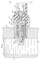
- FIG. 1 is a side sectional view of a switch unit embodying this invention as the switch unit is installed in association with the engine coolant system of an internal combustion engine. This figure illustrates the switch unit in a de-actuated condition.
- FIG. 2 is a side sectional view, similar to FIG. 1, and illustrates the switch unit in an actuated condition.
- FIG. 3 is a sectional view taken substantially on line 3-3 of FIG. 2.
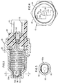
- FIG. 4 is an elevational view taken substantially on line 4-4 of FIG. 1.
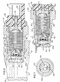
- FIG. 5 is a side sectional view, similar to FIG. 1, showing another embodiment of the switch unit of this invention installed in association with the engine coolant system of an internal combustion system. This figure shows the switch unit in a de- eactuated condition.
- FIG. 6 is a side sectional view of the embodiment shown in FIG. 5 and illustrates the switch unit in an actuated condition.
- FIG. 7 is a sectional view taken substantially on line 7-7 of FIG. 6.
- FIG. 1 illustrates a
switch unit 10 of this invention as it is mounted in awall 12 of afluid conduit 13 of a coolant system of an internal combustion engine. Theconduit 13 forms apassage 14 which is enclosed by thewall 12 and which contains a coolant liquid therewithin. The coolant liquid flows through theconduit 13, through the engine and through a heat exchanger, not shown. - The
switch unit 10 comprises ahousing 20 which is threaded into thewall 12. Secured within one end portion of thehousing 20 is asupport member 26 which is of electrically non-conductive material, such as a plastics material or the like. Shown threaded within thesupport member 26 is an electricallyconductive contact member 34. - The
housing 20 has anend portion 20a which is within thepassage 14. Theend portion 20a has anopening 40 which leads into thehousing 20 and which provides liquid communication between thepassage 14 and the interior of thehousing 20. Abellows 50 is positioned within thehousing 20 and extends lontigudinally within'thehousing 20. Thebellows 50 has abulb end portion 50a which is shown as being elongate in cross section and which is secured within the opening 40 in theend portion 20a of thehousing 20, as illustrated in FIG. 3. Theend portion 20a thus secures thebellows 50 to thehousing 20 but permits flow of liquid between thepassage 14 and the interior of thehousing 20. - The end of the
bellows 50 opposite thebulb end portion 50a includes arigid panel 56 to which is attached atubular stem 60. Thetubular stem 60 is closed by anengagement member 64 which extends therefrom. Thetubular stem 60 is slidably axially movable within thesupport member 26. Under normal conditions within thebellows 50, thetubular stem 60 is positioned so that theengagement member 64 is spaced from thecontact member 34, as illustrated in FIG. 1. Thebellows 50, thepanel 56, thestem 60, and theengagement member 64 are of an electrically conductive material. - Attached to the
contact member 34 is anelectrical conductor 70, which extends from thesupport member 26. Also extending through thesupport member 26 is anelectrical conductor 76 which is connected to anelectrical conductor 80 which extends along thebellows 50 and which is joined to athermistor 86 or any electrical device in which the resistance thereof varies significantly with the temperature thereof. Thethermistor 86 is attached to aprotuberant part 50b of thebulb portion 50a of thebellows 50. - Coolant liquid flows through the
passage 14, and some of the coolant liquid flows into thehousing 20 through the opening 40 and surrounds thebellows 50. Thebellows 50 is evacuated and is partially filled with a vaporizable liquid. The vaporizable liquid within thebellows 50 is preferably a solution having substantially the same formulation as the coolant liquid in thepassage 14, i.e., a solution of about fifty percent blycol and fifty percent water. Thebellows 50 is evacuated and filled through thestem 60, and theengagement member 64 closes thebellows 50. - The
housing 20 is constructed of electrically conductive material and is firmly attached to thewall 12 as illustrated in FIG. 1. Thewall 12 is of electrically conductive material and serves as a "ground" connection in the electrical circuits, discussed below. - A portion of the coolant liquid which flows through the
conduit passage 14 also flows through the opening 40 into thehousing 20 and surrounds thebellows 50. The coolant liquid is heated as the coolant liquid flows through the engine during operation of the engine. The boiling point of the coolant liquid is directly related to the pressure thereof within the engine cooling system. If the pressure of the coolant liquid is greater, the temperature at which the coolant liquid vaporizes or boils is greater. - The pressure which exists within the
passage 14 is the same pressure which exists within thehousing 20 and which is applied to the exterior of thebellows 50. The pressure applied to the exterior of thebellows 50 tends to restrain thebellows 50 against expansion in length. The coolant liquid within thehousing 20 transfers heat through thebellows 50 into the liquid within thebellows 50. When the temperature of the liquid within thebellows 50 is sufficient, the liquid within thebellows 50 vaporizes or boils and applies a pressure within thebellows 50 which urges thebellows 50 to expand in length. If the temperature of the liquid within thebellows 50 increases sufficiently, the vapor pressure within thebellows 50 forces thebellows 50 to expand against the pressure applied by the coolant liquid to the exterior of thebellows 50. As thebellows 50 expands, thestem 60 and theengagement member 64 are moved toward thecontact member 34. If there is sufficient expansion of the length of thebellows 50, theengagement member 64 engages thecontact member 34, and an electrical circuit is established through theconductor 70 to an alarm device, not shown. To provide an electrical circuit to the alarm device, the alarm device is also electrically connected to "ground" and to thewall 12 and to thehousing 20, through thebellows 50 and to theengagement member 64. - Thus, external pressure upon the
bellows 50 is compensated by the pressure of the vapor of the liquid within thebellows 50. As stated, preferably, the liquid within thebellows 50 is of substantially the same composition as the coolant liquid which flows through thepassage 14. Therefore, the liquid within thebellows 50 vaporizes under the same temperature and pressure conditions as the coolant liquid exterior of thebellows 50. Therefore, the pressure and temperature of the coolant liquid which is applied to the exterior surface of thebellows 50 is accurately compensated by response of the liquid within thebellows 50 to temperature and pressure conditions within thebellows 50. When the vapor pressure within thebellows 50 with respect to the liquid and/or vapor pressure external of thebellows 50 is sufficient, thebellows 50 expands to move theengagement member 64 into engagement with thecontact member 34 to establish a portion of an electrical circuit. As shown, thecontact member 34 is threadedly adjustable for adjustment of the temperature at which the electrical circuit is closed. - If there should be a leak in the engine coolant system, or for some other reason, the coolant system does not have liquid therein, operation of the engine results in heating of the
wall 12. The heat in thewall 12 is transmitted through thebulb end portion 50a to thebellows 50. The liquid within thebellows 50 thus is heated and vaporizes and forces expansion of thebellows 50. When this occurs, theengagement member 64 engages thecontact member 34, and an alarm is energized in the manner discussed above. - A temperature indicator instrument, not shown, which is observable by an operator of the engine is connected by means, now shown, to the
electrical conductor 76. As shown, theconductor 76 is connected through theconductor 80 to thethermistor 86. The electrical resistance of thethermistor 86 changes significantly with the temperature of thethermistor 86. Therefore, as thethermistor 86 functions in an electrical circuit of which an indicator instrument is a part, the indicator instrument constantly indicates the temperature of the coolant liquid in thecoolant conduit 14 and/or the temperature of thewall 12. - FIGS. 5, 6, and 7 show another embodiment of the switch unit of this invention.
- FIG. 5 illustrates a
switch unit 110 of this invention as it is mounted in awall 112 of a .fluid conduit 113 of a coolant system of an internal combustion engine. Theconduit 113 forms aconduit passage 114 which is enclosed by thewall 112 and which contains a coolant liquid therewithin which flows through the engine and through a heat exchanger, not shown. - 120 which is shown as being threadedly attached to the
wall 112. As shown in FIG. 5, attached to the right hand portion of thehousing 120 is asupport member 126 which is of electrically non-conductive material, such as a plastics material or the like. Within thesupport member 126 is an electricallyconductive contact member 134. - Opposite the
support member 126 thehousing 120 has anend portion 120a which,is within theconduit passage 114. Theend portion 120a of thehousing 120 has anopening 140 which leads into the interior of thehousing 120. Within theend portion 120a of thehousing 120 is arigid retainer ring 142 which secures.anelastomeric diaphragm 144 within theend portion 120a. An elongate bellows 150 is positioned within thehousing 120. The bellows 150 has asolid end portion 150a, which is best shown in FIG. 7 as being elongate in transverse dimension and is secured within theend portion 120a of thehousing 120. As shown in FIG. 7, in view of the fact that theend portion 120a is elongate, fluid can flow between theend portion 120a and the interior walls of thehousing 120. - Within the
end portion 150a of thebellows 150 is arecess 152. Within therecess 152 is athermistor 154 or any electrical device in which the resistance thereof or voltage thereacross varies significantly with the temperature thereof. Thethermistor 154 is retained within therecess 152 by means of anelastomeric retainer ring 156. Anelectrical conductor 158 is attached to thethermistor 154 and extends therefrom along thebellows 150 and is joined to aconnection terminal 160. Thethermistor 154 is also electrically joined to theend portion 150a of thebellows 150, which is of electrically conductive material. Thehousing 120, to which theend portion 150a of thebellows 150 is joined is also of electrically conductive material. Thus, a "ground" connection for thethermistor 154 to the electrical system of the engine is established through thebellows 150 and thehousing 120. - A
passage 164 extends through theend portion 150a of thebellows 150 and into thebellows 150. A limited quantity of liquid is introduced into thebellows 150 through thepassage 164. Preferably, the liquid introduced into thebellows 150 has substantially the same composition as the composition of the liquid in theconduit passage 114 and within the entire coolant system of the engine. After liquid is introduced into thebellows 150 through thepassage 164, thepassage 164 is closed by means of aclosure member 166 which is inserted into thepassage 164. - The bellows 150 has a
movable end portion 150b, which is opposite theend portion 150a. Theend portion 150b is movable with expansion and contraction of thebellows 150. Attached to themovable end portion 150b is astem 170. With expansion of thebellows 150 and with movement of theend portion 150b, thestem 170 is slidably axially movable within anopening 172 in thesupport member 126. Thestem 120 is of electrically conductive material. Within theopening 172 in theend portion 126 is a stationaryelectrical contact member 176. Attached to theelectrical contact member 176 and extending from thesupport member 126 is anelectrical conductor 180. - Within the
housing 120 and enclosed by thediaphragm 144 is a liquid 184 which is a good heat transfer medium, which is incompressible, and which has good dielectric characteristics. The liquid 184 encompasses thebellows 150. - The
housing 120 is constructed of electrically conductive material and is firmly attached to thewall 112 as illustrated in FIG. 5. Thewall 112 is of electrically conductive material and serves as a "ground" connection in the electrical system of the engine with which the switch unit of this invention is associated. - A portion of the coolant liquid which flows through the
conduit passage 114 also flows through theopening 140 into thehousing 120 and engages thediaphragm 144. The pressure of the coolant liquid in the coolant system and within theconduit passage 114 is transmitted through thediaphragm 144 to the liquid 184 which encompasses thebellows 150 within thehousing 120. - The coolant liquid is heated as the coolant liquid flows through the engine during operation of the engine. The coolant liquid within the
coolant conduit passage 114 transfers heat directly to theend portion 120a of thehousing 120, and to thehousing 120 through thewall 112. Heat then is transmitted through the liquid 184, to thebellows 150 and through thebellows 150 into the liquid within thebellows 150. The temperature of the liquid flowing within thecoolant conduit 114 is, substantially the same temperature which exists in the liquid within thebellows 150. If the temperature of the liquid in thecoolant conduit passage 114 reaches a magnitude in which the liquid boils or vaporizes, the temperature of the liquid within thebellows 150 causes the liquid within thebellows 150 to vaporize. The liquid within thebellows 150 vaporizes or boils and applies a pressure within thebellows 150 which urges thebellows 150 to expand in length. If the temperature of the liquid within thebellows 150 increases sufficiently, the vapor pressure within thebellows 150 forces thebellows 150 to expand against the pressure applied by the liquid 184 which encompasses thebellows 150. The boiling point of the coolant liquid in the coolant system is directly related to the pressure applied to the coolant liquid within the engine coolant system. If the pressure of the coolant liquid is greater, the temperature at which the coolant liquid vaporizes or boils is greater. - The pressure which exists within the
conduit passage 114 is the same pressure which is applied to thediaphragm 144 within theend portion 120a of thehousing 120. The pressure applied to thediaphragm 144 is transmitted to the liquid 184 which fills thehousing 120 and surrounds and encompasses thebellows 150. Thus, the pressure of the coolant fluid within theconduit passage 114 is transmitted through thediaphragm 144 to the liquid 184 within thehousing 120. The pressure of the liquid 184 within thehousing 120 is applied to the exterior of thebellows 150. The pressure applied to the exterior of thebellows 150 tends to restrain thebellows 150 against expansion in length. As thebellows 150 expands, thebellows 150 increases in volume and due to the fact that thebellows 150 is within the liquid 184, which completely fills thehousing 120, expansion of thebellows 150 causes the liquid 184 to force thediaphragm 144 outwardly, as illustrated in FIG. 6. Also, as thebellows 150 expands in length, thestem 170 is moved toward thecontact member 176. If there is sufficient expansion of the length of thebellows 150, thestem 170 engages thecontact member 176, and an electrical circuit is established through theconductor 180 to an alarm device, not shown. - If there should be a leak in the engine coolant system, or for some other reason, the coolant system does not contain a sufficient quantity of coolant liquid to maintain the engine at a proper temperature, operation of the engine results in excessive heating of the
wall 112. The heat in thewall 112 is transmitted through thebellows 150, through the liquid 184, and into thebellows 150. The liquid within thebellows 150 thus is heated and vaporizes and forces expansion of thebellows 150. When this occurs, thestem 170 engages thecontact member 176, as illustrated in FIG. 6, and the alarm is energized in the manner discussed above. - The pressure within the coolant system and within
coolant conduit 114 is transmitted through thediaphragm 144 to the liquid 184 which is within thehousing 120. Pressure of the liquid 184 within thehousing 120 opposes expansion of thebellows 150. Therefore, in order for thebellows 150 to expand sufficiently to cause thestem 170 to engage thecontact member 176, the pressure within thebellows 150 must be greater when the pressure of the liquid in the coolant system is greater. The pressure of the fluid within thebellows 150 is dependent upon the temperature of the fluid within thebellows 150. As stated, the temperature of the fluid within thebellows 150 is substantially the same as the temperature of the liquid in the coolant system and/or the temperature of thewall 112. - Thus, it is to be understood that there is an infinite number of pressure-temperature conditions at which the
stem 170 engages thecontact member 176 to actuate an alarm. Each alarm actuation position is directly related to a given temperature-pressure condition of the liquid in the coolant system. - A proper response by the operator of the engine to alarm conditions will result in avoidance of loss of coolant liquid and thus avoidance of damage to the engine.
- A temperature indicator instrument, not shown, which is observable by an operator of the engine, is connected by means not shown to the
electrical conductor 160. As shown, theconductor 160 is connected to thethermistor 154. The electrical resistance of thethermistor 154 changes significantly with the temperature of thethermistor 154. Thus, through functioning of thethermistor 154 which is in contact with the liquid 184 in thehousing 120, a temperature indicator instrument which is connected to thethermistor 154 always indicates the temperature of the coolant liquid in thecoolant conduit 114 and/or the temperature of thewall 112. - Therefore, in summary, whether or not fluid exists within a coolant system in which a switch unit of this invention is positioned, the switch unit of this invention automatically operates to indicate that temperature conditions harmful to the engine exist when such harmful temperature conditions actually exist and only when harmful temperature conditions exist.
Claims (18)
1. An engine protective switch unit adapted to be mounted in a coolant system of an internal combustion engine for operation of an engine protective monitoring device, the coolant system having a flow passage through which coolant liquid flows, comprising a housing (20,120) provided with a cavity therein, the housing (20, 120) having an opening (40, 140) which, in operation, provides communication between the flow passage of the coolant system and the cavity within the housing, pressure responsive means (50, 150) within the cavity of the housing and having a movable portion (56, 150b) which is subject to pressure within the cavity, an electrical contact member (64, 170), means attaching the electrical contact member (64, 170) to the movable portion (56, 150b) of the pressure sensitive means (50, 150) for movement of the electrical contact member with movement of the movable portion of the pressure responsive means, an electrical engagement member (34, 176) adjacent the electrical contact member (64, 170) and engageable by the electrical contact member (64, 170) with movement of the movable portion of the pressure responsive means, vaporizable liquid within the pressure responsive means 150, 150), the vaporizable liquid, in operation, being heated by the coolant liquid and vaporizable to apply internal pressure upon the movable portion (56, 150b) of the pressure responsive means (50, 150) for movement of the movable portion (56, 150b) of the pressure responsive means (50, 150), the electrical contact member (64, 170) being movable into engagement with the electrical engagement member (34, 176) by vapor pressure within the pressure responsive means (50, 150) which forces movement of the movable portion (56, 150b) of the pressure responsive means (50, 150).
2. The engine protective switch unit of Claim 1 in which the pressure responsive means (50, 150) comprises a bellows.
3. The engine protective switch unit of Claim 1 in which the vaporizable liquid within the pressure responsive means (50, 150) has substantially the same composition as the coolant liquid which flows in the flow passage of the coolant system.
4. The engine protective switch unit of Claim 1 in which the pressure responsive means (50, 150) is attached to the housing (20).
5. The engine protective switch unit of Claim 1 which includes an electrical thermistor device (86, 154) positioned for engagement by liquid which flows in the flow passage of the coolant system.
6. The engine protective switch unit of Claim 1 which includes an electrical device (86, 154) which changes resistance with changes in the temperature thereof, the electrical device (86, 154) being positioned within the cavity of the housing.
7. The engine protective switch unit of Claim 1 in which the pressure responsive means (50, 150) is attached to the housing (20, 120) at a position adjacent the opening (40, 140) in the housing.
8. The engine protective switch unit of Claim 1 in which the engagement member (34, 176) is adjustable with respect to the electrical contact member.
9. The engine protective switch unit of Claim 1 which includes a diaphragm (144) which extends across the opening (140) and encloses the cavity of the housing (120), fluid within the cavity of the housing (120) and encompassing the pressure responsive means and filling the space in the cavity which is not occupied by the pressure responsive means (150).
10. The engine protective switch unit of Claim 1 which includes an electrical device (86, 154) in which the electrical resistance thereof varies with the temperature thereof, the electrical device (86, 154) being positioned to be responsive to the temperature of the coolant liquid within the coolant system.
11. The engine protective switch unit of Claim 2 in which the bellows (50, 150) has a movable portion (56, 150b) and in which the electrical contact member is attached to the movable portion (56, 150) of the bellows for movement with the movable portion (56, 150b) of the bellows (50, 150).
12. The engine protective switch unit of Claim 1 in which the housing (20, 120) includes a support portion (26, 126) of electrical insulator material, and in which the electrical engagement member (34, 176) is carried by the support portion (26, 126) of insulator material.
13. The engine protective switch of Claim 2 in which the fluid in the bellows (50, 150) is a vaporizable liquid.
14. The engine protective switch of Claim 2 in which the coolant system contains a liquid and in which the fluid in the bellows (50, 150) has substantially the same composition as the liquid in the coolant system.
15. The engine protective switch unit of Claim 1 which includes an electrical resistance device positioned within the housing (20, 120), the electrical resistance device being of the type in which the electrical resistance thereof varies significantly with variations in the temperature of the electrical resistance device, and wherein the electrical resistance device is adapted to be electrically connected to an engine monitoring instrument.
16. The engine protective switch unit of Claim 2 in which the housing (120) has a cavity therein and in which the opening (140) in the housing (120) leads to the cavity, a diaphragm (144) extending across the opening (140) and separating the cavity from the exterior of the housing (120), the bellows (150) being positioned within the cavity, a liquid within the cavity and encompassing the bellows (150), the liquid encompassing the bellows and filling the cavity and transmitting pressure and temperature to the bellows and to the fluid within the bellows.
17. The method of protection of an internal combustion engine which is provided with a coolant system through which coolant fluid flows comprising:
establishing the magnitude of temperature and pressure conditions within the coolant system to be considered as danger conditions,
sensing the temperature and sensing the pressure of the coolant fluid in the collant system,
and energizing an alarm when pressure and temperature conditions of the coolant fluid are of a magnitude considered as danger conditions.
18. The method of Claim 17 in which the sensing includes positioning sensing means in communication with the coolant system, in which the sensing means senses the temperature and in which the sensing means includes means sensing the pressure of the coolant fluid.
Applications Claiming Priority (2)
| Application Number | Priority Date | Filing Date | Title |
|---|---|---|---|
| US06/680,279 US4587931A (en) | 1984-12-10 | 1984-12-10 | Pressure compensated temperature switch unit for protection of an internal combustion engine |
| US680279 | 2000-10-06 |
Publications (2)
| Publication Number | Publication Date |
|---|---|
| EP0186331A2 true EP0186331A2 (en) | 1986-07-02 |
| EP0186331A3 EP0186331A3 (en) | 1989-02-22 |
Family
ID=24730457
Family Applications (1)
| Application Number | Title | Priority Date | Filing Date |
|---|---|---|---|
| EP85308672A Withdrawn EP0186331A3 (en) | 1984-12-10 | 1985-11-28 | Pressure compensated temperature switch unit for protection of an internal combustion engine |
Country Status (7)
| Country | Link |
|---|---|
| US (1) | US4587931A (en) |
| EP (1) | EP0186331A3 (en) |
| JP (1) | JPS61138818A (en) |
| CN (1) | CN1006260B (en) |
| BR (1) | BR8506164A (en) |
| CA (1) | CA1251503A (en) |
| ES (1) | ES8705566A1 (en) |
Cited By (1)
| Publication number | Priority date | Publication date | Assignee | Title |
|---|---|---|---|---|
| EP2837788A4 (en) * | 2012-03-16 | 2016-02-17 | Aichi Machine Ind | Structure for retaining temperature sensing device and internal combustion engine provided with same |
Families Citing this family (9)
| Publication number | Priority date | Publication date | Assignee | Title |
|---|---|---|---|---|
| US4630036A (en) * | 1983-01-26 | 1986-12-16 | Vernay Laboratories, Inc. | Early warning of marine cooling system failure |
| US4702620A (en) * | 1985-04-04 | 1987-10-27 | Autotec International, Inc. | Methods of and apparatus for testing internal combustion engines by monitoring the cooling systems thereof |
| US4691669A (en) * | 1986-03-17 | 1987-09-08 | Otteman John H | Engine overheat protection system |
| DE3627511A1 (en) * | 1986-08-13 | 1988-02-18 | Bayerische Motoren Werke Ag | FUEL TEMPERATURE DISPLAY DEVICE FOR INTERNAL COMBUSTION ENGINES, IN PARTICULAR COOLANT TEMPERATURE INDICATOR DEVICE FOR LIQUID-COOLED INTERNAL COMBUSTION ENGINES |
| US5046857A (en) * | 1990-05-23 | 1991-09-10 | General Motors Corporation | Plastic thermal probe assembly with press fit sensor |
| DE4113294C1 (en) * | 1991-04-24 | 1992-06-17 | Fa. Carl Freudenberg, 6940 Weinheim, De | |
| JP3146405B2 (en) * | 1994-04-27 | 2001-03-19 | 日本サーモスタット株式会社 | Temperature sensor |
| US5971288A (en) * | 1997-04-22 | 1999-10-26 | Standard-Thomson Corporation | Expansion composition |
| US5949324A (en) * | 1997-12-29 | 1999-09-07 | Segler; John M. | Temperature responsive probe apparatus |
Family Cites Families (7)
| Publication number | Priority date | Publication date | Assignee | Title |
|---|---|---|---|---|
| GB488838A (en) * | 1937-08-26 | 1938-07-14 | Gen Motors Corp | Electrical temperature-responsive units |
| US3753256A (en) * | 1971-08-31 | 1973-08-14 | Raymond Lee Organization Inc | Fire alarm system |
| US3898614A (en) * | 1974-09-16 | 1975-08-05 | Gen Motors Corp | Engine overheat sensor |
| US4262274A (en) * | 1979-04-13 | 1981-04-14 | General Motors Corporation | Thermal electric switch |
| US4299117A (en) * | 1979-11-23 | 1981-11-10 | The Bendix Corporation | Multi-function engine sensor |
| FR2488039A1 (en) * | 1980-07-29 | 1982-02-05 | Calorstat Investissements | Thermal contact for pressurised coolant in IC engine - has capsule containing liquid and saturated liquid vapour, and is expandable on coolant pressure loss to close warning circuit |
| DE8312296U1 (en) * | 1983-04-27 | 1983-12-01 | Ranco Inc., 43017 Dublin, Ohio | Temperature-dependent switch |
-
1984
- 1984-12-10 US US06/680,279 patent/US4587931A/en not_active Expired - Fee Related
-
1985
- 1985-10-22 CA CA000493532A patent/CA1251503A/en not_active Expired
- 1985-11-28 EP EP85308672A patent/EP0186331A3/en not_active Withdrawn
- 1985-12-04 CN CN85108787.6A patent/CN1006260B/en not_active Expired
- 1985-12-09 JP JP60275243A patent/JPS61138818A/en active Pending
- 1985-12-09 ES ES549735A patent/ES8705566A1/en not_active Expired
- 1985-12-09 BR BR8506164A patent/BR8506164A/en unknown
Cited By (1)
| Publication number | Priority date | Publication date | Assignee | Title |
|---|---|---|---|---|
| EP2837788A4 (en) * | 2012-03-16 | 2016-02-17 | Aichi Machine Ind | Structure for retaining temperature sensing device and internal combustion engine provided with same |
Also Published As
| Publication number | Publication date |
|---|---|
| EP0186331A3 (en) | 1989-02-22 |
| ES549735A0 (en) | 1987-05-01 |
| CN1006260B (en) | 1989-12-27 |
| ES8705566A1 (en) | 1987-05-01 |
| CN85108787A (en) | 1986-09-17 |
| US4587931A (en) | 1986-05-13 |
| BR8506164A (en) | 1986-08-26 |
| JPS61138818A (en) | 1986-06-26 |
| CA1251503A (en) | 1989-03-21 |
Similar Documents
| Publication | Publication Date | Title |
|---|---|---|
| EP0186331A2 (en) | Pressure compensated temperature switch unit for protection of an internal combustion engine | |
| CA1102858A (en) | Engine coolant heater with control thermostat | |
| US5020325A (en) | Heat motor | |
| US5669263A (en) | Probe for monitoring liquid with protection against leakage | |
| EP0125366B1 (en) | Temperature sensors | |
| US2928037A (en) | Thermistor liquid level switch | |
| US4633213A (en) | Pressure temperature sensor | |
| KR910017145A (en) | Refrigerant device using thermal expansion valve | |
| CA1097717A (en) | Explosion resistant overload and relay mounting for explosion resistant motor | |
| GB2156436A (en) | Pressure medium accumulator | |
| US4672920A (en) | Pressure compensated temperature switch unit for protection of an internal combustion engine | |
| US4630028A (en) | Pressure-biased, temperature sensor | |
| US4773350A (en) | Fusible temperature signaling sensor | |
| US3593270A (en) | Liquid level sensing and indicating system | |
| US5386100A (en) | Control arrangement for immersion liquid heaters | |
| US4652854A (en) | Pressure-biased, temperature sensor | |
| US4663608A (en) | Pressure-biased, temperature sensor | |
| US3335243A (en) | Bimetal indicator device with a heater energized under all operative conditions | |
| WO1983000765A1 (en) | Fluid level and temperature sensor | |
| US4346558A (en) | Thermal actuator with lock open feature | |
| US3221125A (en) | Temperature switch having slidable thermal exchanger | |
| JP2879402B2 (en) | Hermetic thermal device | |
| US3562546A (en) | Apparatus for limiting the level of a liquid in a container | |
| US6720535B2 (en) | Explosion protected heating system for heating an enclosure with two temperature control algorithms | |
| SU783902A1 (en) | Thermoanemometric relay for thermal protection of electric equipment |
Legal Events
| Date | Code | Title | Description |
|---|---|---|---|
| PUAI | Public reference made under article 153(3) epc to a published international application that has entered the european phase |
Free format text: ORIGINAL CODE: 0009012 |
|
| AK | Designated contracting states |
Kind code of ref document: A2 Designated state(s): BE DE FR GB IT SE |
|
| PUAL | Search report despatched |
Free format text: ORIGINAL CODE: 0009013 |
|
| AK | Designated contracting states |
Kind code of ref document: A3 Designated state(s): BE DE FR GB IT SE |
|
| STAA | Information on the status of an ep patent application or granted ep patent |
Free format text: STATUS: THE APPLICATION IS DEEMED TO BE WITHDRAWN |
|
| 18D | Application deemed to be withdrawn |
Effective date: 19890823 |
|
| RIN1 | Information on inventor provided before grant (corrected) |
Inventor name: DUPREZ, WAYNE ROBERT |