EP0186358A2 - Dispositif pour la mesure de résistance de tirage - Google Patents
Dispositif pour la mesure de résistance de tirage Download PDFInfo
- Publication number
- EP0186358A2 EP0186358A2 EP85308911A EP85308911A EP0186358A2 EP 0186358 A2 EP0186358 A2 EP 0186358A2 EP 85308911 A EP85308911 A EP 85308911A EP 85308911 A EP85308911 A EP 85308911A EP 0186358 A2 EP0186358 A2 EP 0186358A2
- Authority
- EP
- European Patent Office
- Prior art keywords
- torque
- disc
- pulling
- axis
- pull
- Prior art date
- Legal status (The legal status is an assumption and is not a legal conclusion. Google has not performed a legal analysis and makes no representation as to the accuracy of the status listed.)
- Withdrawn
Links
- 238000012360 testing method Methods 0.000 claims abstract description 23
- 229910000639 Spring steel Inorganic materials 0.000 claims description 3
- 125000006850 spacer group Chemical group 0.000 claims 1
- 239000000463 material Substances 0.000 description 3
- 238000006243 chemical reaction Methods 0.000 description 2
- 238000010276 construction Methods 0.000 description 1
- 229910052602 gypsum Inorganic materials 0.000 description 1
- 239000010440 gypsum Substances 0.000 description 1
- 238000005259 measurement Methods 0.000 description 1
Images
Classifications
-
- G—PHYSICS
- G01—MEASURING; TESTING
- G01N—INVESTIGATING OR ANALYSING MATERIALS BY DETERMINING THEIR CHEMICAL OR PHYSICAL PROPERTIES
- G01N3/00—Investigating strength properties of solid materials by application of mechanical stress
-
- G—PHYSICS
- G01—MEASURING; TESTING
- G01L—MEASURING FORCE, STRESS, TORQUE, WORK, MECHANICAL POWER, MECHANICAL EFFICIENCY, OR FLUID PRESSURE
- G01L5/00—Apparatus for, or methods of, measuring force, work, mechanical power, or torque, specially adapted for specific purposes
- G01L5/0028—Force sensors associated with force applying means
- G01L5/0033—Force sensors associated with force applying means applying a pulling force
Definitions
- the present invention relates to an apparatus for measuring the pull-out resistance of articles embedded in a workpiece. More particularly, the invention relates to a device for making field measurements of fasteners used in the roofing industry.
- roofing particularly in roof repair, a problem frequently encountered is a wide variation in the strength of the material to which the roof is applied. Varying conditions of disrepair can create widely varying conditions in the field. To avoid unnecessarily frequent placement of roof fixing anchors or fasteners, it is necessary to get large quantities of test data to evaluate the material into which the anchors or fasteners are to be placed. The presence or lack of moisture in roofing material such as gypsum or light weight concrete, can create particularly wide variations in pull-out strength.
- an apparatus for testing pull-out strength of fasteners comprises a base, a pulling member rotatably mounted on the base for rotation about an axis and having bearing surface, which is located at a constant distance from the axis, flexible pulling means fixed to the member for pulling a fastener along a line tangential to the bearing surface, and a lever arm extending from the pulling member and including torque measuring means for measuring the torque exerted about the axis.
- the present invention provides a portable testing apparatus for testing fasteners in the field which can be used to quickly test fasteners to gather large amounts of test data. It provides a simple, low cost, and durable testing apparatus which can be used by field engineers to determine the placement array of fasteners in a roofing construction.
- a particular example of the present invention comprises a generally flat, at least partially cylindrical disc which is rotatably mounted on a support.
- the support is comprised of a pair of L-shaped plates which support an axle about which the disc rotates.
- a flexible spring steel strap is mounted on the disc and extends down to the bottom of the plates.
- the end of the strap contains a fastener holding block which is adapted to receive the head of a test fastener.
- Extending rigidly from the disc is a lever arm, which preferably includes a torque wrench which measures torque about the centre of the disc.
- the torque wrench measures torque in inch-pounds, and the radius of the disc is approximately one inch.
- the torque reading therefore, is directly convertible to pull-out load associated with the test fastener. Because the spring steel strap is flexible, the line of pull-out is tangential tb the disc, which makes the torque reading an accurate measure of pull-out resistance of the test fastener.
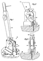
- Figure 1 shows the apparatus 10 comprised of a base 12 which is made up of two plates 14 which support a pulling member or disc 16. Extending from the disc is a lever arm 18 which includes a torque wrench 20. Also attached to the disc and extending in a downward direction is a flexible tension strap 22.
- the disc 16 is a generally flat cylindrical member with a bearing surface 35 on the periphery of the disc 16. The bearing surface 35 abuts the strap 22 during a test.
- the apparatus in Figure 1 is shown in its position just prior to its engagement with a test fastener 24.
- the fastener holding block 26 attached to the free end of the strap 22 is adapted to engage the head of the test fastener 24.
- the spacing foot 28 is used to place the head of the fastener a predetermined distance above the workpiece surface 30.
- the spacing foot 28 includes an open slot 29 which allows the apparatus to be moved laterally out of engagement with the fastener head when the fastener has been installed to a predetermined level.
- FIG 2 shows the apparatus 10 in engagement with the test fastener 24.
- the axle 32 supports the bearing 33 around which the disc 16 rotates.
- the outer periphery of the disc 16 includes a bearing surface 35.
- the strap 22 is fastened to the disc 16 by a screw 36.
- the bearing surface 35 is disposed at a constant radius from the axle 32.
- the flexible strap 22 is adapted to ride on the bearing surface 35 in order to pull the fastener 24 along a line tangent to the bearing surface 35.
- the radius "R" which corresponds to the distance of the bearing surface 35 from the centre of the disc "C”, is preferably one inch, (25.4 mm).
- the holding block 26 is attached to the free end of the strap 22 by a screw 37.
- the block 26 is comprised of a pair of intersecting slots 39 and 40.
- the lateral slot 39 extends into the block deep enough to accommodate the full fastener head.
- the vertical slot 40 extends through the bottom of the block 26. It should be noted that the axis of the fastener should be aligned with th centre of the strap 22 in order to avoid eccentricity during the pull-out of the test fastener 24.
- the slot 24 is deep enough in the horizontal direction to allow such alignment.
- a spacing block 42 is used to hold the plates apart.
- the spacing block 42 is slightly wider than the disc 16 so that the disc 16 freely rotates between the plates 14.
- the operation of the apparatus 10 is as follows.
- a test fastener 24 is placed in the slot 29 in the spacing foot 28 and is driven into the workpiece surface 30.
- the holding block 26 which is attached to the free end of the flexible strap 22 is moved into engagement with the fastener head.
- the axis of the fastener 24 is aligned with the centre of the flexible strap when the strap 22 is in a vertical position.
- the torque wrench 20 and the lever arm 18 the disc 16 rotates about its centre "C”.
- the strap 22 moves upward along the line tangent to the outer periphery of the disc 16 at the bearing surface 35.
- the test fastener 24 is extracted from the workpiece.
Landscapes
- Chemical & Material Sciences (AREA)
- Analytical Chemistry (AREA)
- Physics & Mathematics (AREA)
- General Physics & Mathematics (AREA)
- Health & Medical Sciences (AREA)
- Life Sciences & Earth Sciences (AREA)
- Biochemistry (AREA)
- General Health & Medical Sciences (AREA)
- Immunology (AREA)
- Pathology (AREA)
- Investigating Strength Of Materials By Application Of Mechanical Stress (AREA)
- Measurement Of Resistance Or Impedance (AREA)
Applications Claiming Priority (2)
| Application Number | Priority Date | Filing Date | Title |
|---|---|---|---|
| US67984384A | 1984-12-10 | 1984-12-10 | |
| US679843 | 2000-10-05 |
Publications (2)
| Publication Number | Publication Date |
|---|---|
| EP0186358A2 true EP0186358A2 (fr) | 1986-07-02 |
| EP0186358A3 EP0186358A3 (fr) | 1987-06-16 |
Family
ID=24728600
Family Applications (1)
| Application Number | Title | Priority Date | Filing Date |
|---|---|---|---|
| EP85308911A Withdrawn EP0186358A3 (fr) | 1984-12-10 | 1985-12-06 | Dispositif pour la mesure de résistance de tirage |
Country Status (3)
| Country | Link |
|---|---|
| EP (1) | EP0186358A3 (fr) |
| AU (1) | AU4977085A (fr) |
| CA (1) | CA1249733A (fr) |
Cited By (4)
| Publication number | Priority date | Publication date | Assignee | Title |
|---|---|---|---|---|
| EP0448277A1 (fr) * | 1990-03-21 | 1991-09-25 | Ford Motor Company Limited | Dispositif pour un test de sécurité |
| GB2303927A (en) * | 1995-08-03 | 1997-03-05 | Scovill Japan | Pluck-resistance measuring instrument and method for snap members |
| GB2330915A (en) * | 1995-08-03 | 1999-05-05 | Scovill Japan | Pluck resistance measuring instrument and method for snap members |
| WO2010049461A1 (fr) * | 2008-10-31 | 2010-05-06 | Inventio Ag | Outil destiné à contrôler un boulon et procédé de contrôle |
Families Citing this family (1)
| Publication number | Priority date | Publication date | Assignee | Title |
|---|---|---|---|---|
| CN109515740A (zh) * | 2018-11-05 | 2019-03-26 | 西安飞机工业(集团)有限责任公司 | 一种飞机襟翼系统扭力矩测量方法 |
Family Cites Families (4)
| Publication number | Priority date | Publication date | Assignee | Title |
|---|---|---|---|---|
| GB1284072A (en) * | 1968-08-07 | 1972-08-02 | Nat Res Dev | Testing of concrete |
| US4217776A (en) * | 1978-05-12 | 1980-08-19 | Texaco Inc. | Anchor pullout testing apparatus and methods |
| CA1076835A (fr) * | 1979-03-27 | 1980-05-06 | Andre Tremblay | Appareil d'essai pour boulon d'ancrage |
| DE3010456A1 (de) * | 1980-03-19 | 1981-09-24 | Herberts Gmbh, 5600 Wuppertal | Verfahren und vorrichtung zum messen der zugfestigkeit von putz |
-
1985
- 1985-11-04 CA CA000494557A patent/CA1249733A/fr not_active Expired
- 1985-11-12 AU AU49770/85A patent/AU4977085A/en not_active Abandoned
- 1985-12-06 EP EP85308911A patent/EP0186358A3/fr not_active Withdrawn
Cited By (7)
| Publication number | Priority date | Publication date | Assignee | Title |
|---|---|---|---|---|
| EP0448277A1 (fr) * | 1990-03-21 | 1991-09-25 | Ford Motor Company Limited | Dispositif pour un test de sécurité |
| GB2303927A (en) * | 1995-08-03 | 1997-03-05 | Scovill Japan | Pluck-resistance measuring instrument and method for snap members |
| US5798467A (en) * | 1995-08-03 | 1998-08-25 | Scovill Japan Kabushiki Kaisha | Pluck resistance measuring instrument for snap members |
| GB2330915A (en) * | 1995-08-03 | 1999-05-05 | Scovill Japan | Pluck resistance measuring instrument and method for snap members |
| GB2303927B (en) * | 1995-08-03 | 1999-07-14 | Scovill Japan | Pluck-resistance measuring instrument and method for snap members |
| GB2330915B (en) * | 1995-08-03 | 1999-07-14 | Scovill Japan | Pluck-resistance measuring instrument and method for snap members |
| WO2010049461A1 (fr) * | 2008-10-31 | 2010-05-06 | Inventio Ag | Outil destiné à contrôler un boulon et procédé de contrôle |
Also Published As
| Publication number | Publication date |
|---|---|
| EP0186358A3 (fr) | 1987-06-16 |
| AU4977085A (en) | 1986-06-19 |
| CA1249733A (fr) | 1989-02-07 |
Similar Documents
| Publication | Publication Date | Title |
|---|---|---|
| US4662227A (en) | Apparatus for measuring pull-out resistance | |
| US4753115A (en) | Pullout force measuring apparatus | |
| US5731525A (en) | Extraction force tester | |
| US8800392B2 (en) | Deformation testing device | |
| US4543814A (en) | Device for calibrating torque transducers | |
| US9921122B2 (en) | Torque wrench calibration | |
| US6199427B1 (en) | Apparatus and method for testing leaf springs | |
| EP0186358A2 (fr) | Dispositif pour la mesure de résistance de tirage | |
| US5689072A (en) | Method and apparatus for preloading a skid plate for an early cutting concrete saw | |
| CA1071889A (fr) | Durometre | |
| US4972719A (en) | Dynamic load stress tester | |
| JP3859655B2 (ja) | 試験機 | |
| CN220472917U (zh) | 一种弹簧弹力测试机 | |
| CN215065918U (zh) | 锚固试验机校准装置 | |
| CN117309213A (zh) | 一种木结构无损检测设备及方法 | |
| US4137759A (en) | Belt tension indicating apparatus | |
| CN2164038Y (zh) | 一种制动力测试台的校验装置 | |
| CN221565432U (zh) | 一种电梯检验检测用钢丝绳张力测力计 | |
| CN223377066U (zh) | 一种隔离加载设备和反力面接触的锚杆检测装置 | |
| US5181426A (en) | Apparatus for simultaneous measurement of radial forces in a ring-like clamp | |
| CN213022696U (zh) | 一种砂浆回弹仪 | |
| CN219302241U (zh) | 工件拉拔力测试装置 | |
| CN222143990U (zh) | 一种小麦株高穗长快速测量装置 | |
| CN210513931U (zh) | 一种拉伸试验延伸率测量辅助装置 | |
| CN113588226B (zh) | 一种拉簧极限拉力测试装置及其测试方法 |
Legal Events
| Date | Code | Title | Description |
|---|---|---|---|
| PUAI | Public reference made under article 153(3) epc to a published international application that has entered the european phase |
Free format text: ORIGINAL CODE: 0009012 |
|
| AK | Designated contracting states |
Kind code of ref document: A2 Designated state(s): BE CH DE FR GB LI NL |
|
| PUAL | Search report despatched |
Free format text: ORIGINAL CODE: 0009013 |
|
| AK | Designated contracting states |
Kind code of ref document: A3 Designated state(s): BE CH DE FR GB LI NL |
|
| 17P | Request for examination filed |
Effective date: 19871127 |
|
| 17Q | First examination report despatched |
Effective date: 19910318 |
|
| STAA | Information on the status of an ep patent application or granted ep patent |
Free format text: STATUS: THE APPLICATION IS DEEMED TO BE WITHDRAWN |
|
| 18D | Application deemed to be withdrawn |
Effective date: 19910703 |
|
| RIN1 | Information on inventor provided before grant (corrected) |
Inventor name: PETERSON, FRANCIS C. |