EP0186408B1 - Schneidelement für Drehbohrmeissel - Google Patents
Schneidelement für Drehbohrmeissel Download PDFInfo
- Publication number
- EP0186408B1 EP0186408B1 EP85309156A EP85309156A EP0186408B1 EP 0186408 B1 EP0186408 B1 EP 0186408B1 EP 85309156 A EP85309156 A EP 85309156A EP 85309156 A EP85309156 A EP 85309156A EP 0186408 B1 EP0186408 B1 EP 0186408B1
- Authority
- EP
- European Patent Office
- Prior art keywords
- cutting
- blank
- cutting element
- portions
- projecting
- Prior art date
- Legal status (The legal status is an assumption and is not a legal conclusion. Google has not performed a legal analysis and makes no representation as to the accuracy of the status listed.)
- Expired
Links
Images
Classifications
-
- E—FIXED CONSTRUCTIONS
- E21—EARTH OR ROCK DRILLING; MINING
- E21B—EARTH OR ROCK DRILLING; OBTAINING OIL, GAS, WATER, SOLUBLE OR MELTABLE MATERIALS OR A SLURRY OF MINERALS FROM WELLS
- E21B10/00—Drill bits
- E21B10/46—Drill bits characterised by wear resisting parts, e.g. diamond inserts
- E21B10/56—Button-type inserts
- E21B10/567—Button-type inserts with preformed cutting elements mounted on a distinct support, e.g. polycrystalline inserts
- E21B10/5673—Button-type inserts with preformed cutting elements mounted on a distinct support, e.g. polycrystalline inserts having a non planar or non circular cutting face
-
- Y—GENERAL TAGGING OF NEW TECHNOLOGICAL DEVELOPMENTS; GENERAL TAGGING OF CROSS-SECTIONAL TECHNOLOGIES SPANNING OVER SEVERAL SECTIONS OF THE IPC; TECHNICAL SUBJECTS COVERED BY FORMER USPC CROSS-REFERENCE ART COLLECTIONS [XRACs] AND DIGESTS
- Y10—TECHNICAL SUBJECTS COVERED BY FORMER USPC
- Y10T—TECHNICAL SUBJECTS COVERED BY FORMER US CLASSIFICATION
- Y10T407/00—Cutters, for shaping
- Y10T407/26—Cutters, for shaping comprising cutting edge bonded to tool shank
Definitions
- the invention relates to cutting elements for rotary drill bits for use in drilling or coring deep holes in subsurface formations.
- Rotary drill bits of the kind to which the present invention is applicable comprise a bit body having a shank for connection to a drill string and an inner channel for supplying drilling fluid to the face of the bit.
- the bit body carries a plurality of so-called 'preform' cutting elements.
- Each cutting element may be mounted directly on the bit body or on a carrier, such as a stud or post, which is received in a socket in the bit body.
- One common form of preform cutting element comprises a tablet having a hard facing layer of polycrystalline diamond or other superhard material and a backing layer formed of cemented tungsten carbide (see US-A-4 221 270).
- the two-layer arrangement of the cutting element provides a degree of self sharpening since, in use, the less hard backing layer wears away more easily than the harder cutting layer.
- Another form of cutting element comprises a single unitary tablet of thermally stable polycrystalline diamond material.
- the preform cutting elements which are formed under massive pressure in a press, are most often in the form of circular discs and are mounted on the drill bit so that, in use, each element wears away along one portion of its peripheral edge.
- other configurations of cutting element are known, for example sector-shaped, square and triangular elements, where the cutting action is performed by a projecting angular portion of the cutting element.
- a cutting element for a rotary drill bit, comprising a tablet having a front face, a rear face and a peripheral edge, at least the front face of the tablet being provided by a layer of superhard material, and the peripheral edge of the tablet being formed with at least one re-entrant portion so as to define a projecting cutting portion to at least one side of the re-entrant portion.
- the tablet may comprise a front cutting layer of superhard material, such as polycrystalline diamond, bonded to a less hard backing layer, the superhard material defining the front face of the tablet and the backing layer defining the rear face of the tablet.
- the tablet may comprise a single unitary layer of superhard material, such as polycrystalline diamond, which defines both the front face and the rear face of the tablet.
- each re-entrant portion may be provided a projecting cutting element at each side of each re-entrant portion, thereby to provide at least two projecting cutting portions.
- the tablet may be formed, along a part of the peripheral edge thereof, with a plurality of alternate re-entrant and projecting portions so as to provide three or more projecting portions.
- the extremities of all the projecting cutting portions may lie on a substantially straight line so that, in use of the cutting element, they act simultaneously on the formation being drilled.
- the extremities of only some of the projecting portions may lie on a substantially straight line, the extremities of at least one other projecting portion being displaced from said straight line.
- the periphery of the cutting element apart from said re-entrant portion or portions, may be part-circular in configuration.
- the tablet may be in the form of a section of an annulus, having a concavely curved edge portion and an opposite, concentric, convexly curved edge portion.
- the opposite concavely and convexly curved edge portions may be connected by two substantially straight opposite edge portions which extend substantially radially with respect to the annulus.
- the invention includes within its scope a cutting assembly, for use on a drill bit, comprising a cutting element according to the invention mounted on a carrier, such as a stud or post.
- the invention also includes a rotary drill bit having mounted thereon a plurality of cutting elements according to the invention.
- the invention also provides a method of forming a cutting element of any of the kinds referred to above, which method comprises forming in a forming press a preform blank, the periphery of which has no re-entrant portions, and then subsequently cutting into the preform blank at least one re-entrant portion so as to define a projecting cutting portion at each side of the re-entrant portion.
- the cutting of the preform blank may be effected by electric discharge maching or by a laser, or by any other suitable method.
- the method may comprise cutting into the preform blank a plurality of alternate re-entrant and projecting portions.
- the alternate re-entrant and projecting portions may be cut across the centre of the blank so as to form from the blank two essentially similar cutting elements.
- the blank when it is substantially symmetrical, it may be cut into four substantially similar segments the lines of cut also forming each segment with at least one re- entrant portion so as to define a projecting cutting portion at each side of the re-entrant portion.
- the preform blank may be substantially circular before being cut.
- the method may include the steps of cutting from the circular preform blank a central concentric portion of smaller diameter to leave an annular blank, and then cutting the annular blank into sections, each cut extending from the inner peripheral edge of the blank to the outer peripheral edge thereof.
- the annular blank may be cut into sections by a plurality of substantially radially extending cuts.
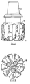
- Figures 1 and 2 show a typical full bore drill bit of a kind to which cutting elements of the present invention are applicable.
- the bit body 10 is typically formed of tungsten carbide matrix infiltrated with a binder alloy, and has a threaded shank 11 at one end for connection to the drill string.
- the operative end face 12 of the bit body is formed with a number of blades 13 radiating from the central area of the bit, and the blades carry cutting members 14 spaced apart along the length thereof.
- the bit has a gauge section including kickers 16 which contact the walls of the bore hole to stabilise the bit in the bore hole.
- a central channel (not shown) in the bit body and shank delivers drilling fluid through nozzles 17 in the end face 12 in known manner.
- Each cutting member 14 comprises a preform cutting element mounted on a carrier in the form of a stud which is located in a socket in the bit body.
- each preform cutting element is usually in the form of a circular tablet comprising a thin facing layer of polycrystalline diamond bonded to a backing layer of tungsten carbide, both layers being of uniform thickness.
- the rear surface of the backing layer of each cutting element is bonded, for example by LS bonding, to a suitably orientated surface on the stud, which may also be formed from tungsten carbide.
- each preform cutting element comprises a unitary tablet of thermally stable polycrystalline diamond material.
- the cutting elements may be mounted directly on the bit body instead of being mounted on studs.
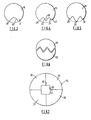
- Figure 3 shows a cutting element according to the invention which is modified from a standard circular preform.
- the circular tablet-like blank 18 is cut by electric discharge machining or by a laser to form a single re-entrant portion 19 which has the effect of defining, on opposite sides of the re-entrant portion, projecting cutting portions 20 and 21.
- the cutting element is so mounted on the drill bit that the projecting portions 20 and 21 act on the formation being drilled.
- Figure 4 shows an alternative arrangement whereby a circular blank 22 is formed with two reentrant portions 23 and 24 to provide three projecting cutting portions 25, 26 and 27. It will be noted that the reentrant portions 23 and 24 are so formed that the extremities of the projecting portions lie along a substantially straight line so that all the projecting cutting portions act on the formation simultaneously.
- each cutting portion 28, 29 and 30 extends to the periphery of the circular blank 31 so that the centre projecting portion 29 projects beyond the straight line connecting the extremities of the projecting portions 28 and 30. Consequently, when the cutting element is new only the cutting portion 29 acts on the formation, but after it has worn down the other two cutting portions 28 and 30 are brought into action. This may extend the overall effective life of the cutting element.
- FIG. 3 to 5 are each formed from a single circular preform blank.
- Figure 6 shows an arrangement whereby two cutting elements may be formed from a single blank. In this case the blank is cut across its centre along a zig-zag line so as to divide the blank into two similar halves 32 and 33, each half being formed with a plurality of alternating re- entrant portions and projecting cutting portions.
- the circular blank from which the cutting elements are formed may be of the conventional diameter of the normal circular cutting element.
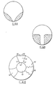
- Figure 7 shows how a larger diameter circular element 34 (for example 34 mm in diameter) may be divided to form four generally sector-shaped cutting elements 35, 36, 37 and 38. The angular portion of each sector is cut to form a re-entrant portion, such as indicated at 39, and thus provides each cutting element with projecting cutting portions 40,41.
- the basic preform blank is circular, it will be appreciated that the invention is equally applicable to the use of preforms of other configurations, such as rectangular or triangular preforms, the essential feature of the invention being that the preforms are modified by cutting at least one re-entrant portion to form one or more projecting cutting portions.
- the sides of the projecting cutting portion are substantially parallel so that the cutting element does not increase significantly in width as it wears down during use. This is advantageous since it means that the rubbing area of the cutting element on the formation does not increase with wear, which would otherwise increase the resistance to rotation of the bit as well as impairing the effectiveness of the cutting elements.
- Figures 10, 11 and 12 there are also shown, in dotted lines, the relative positions of cutting elements on different portions of the surface of the bit body, as viewed in the direction of cutting movement of the elements. It will thus be seen that the paths swept by the cutting elements are immediately adjacent or overlap to ensure removal of formation over a continuous area.
- the arrangement may be such, as shown in Figures 10 and 11, that a cutter slightly overlaps the path of the next cutter on one side but does not overlap the path of the cutter on the other side.
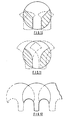
- Figure 13 illustrates a method whereby a number of cutting elements in accordance with the invention may be cut from a single large circular blank.
- the basic circular blank produced in the conventional high pressure forming process is indicated at 42 and may be, for example, 38 mm or 50 mm in diameter.
- a central circular portion, indicated at 43, is cut from the centre of the blank and concentric therewith by electric discharge machining or other suitable cutting process. This circular portion is cut to such a diameter that it may be used in conventional manner on a drill bit of a type using such circular preforms. For example its diameter may be 13.3 mm, 19 mm or 25 mm.
- the remaining annulus is cut into sec- tionsby a plurality of generally radially extending cuts so as to provide a number of similarly shaped preforms.
- one such preform is indicated at 44 and comprises an inner concavely curved edge 45, an outer convexly curved edge 46 and two radially extending straight side edges 47.
- the concavity of the inner edge 45 constitutes the re-entrant portion according to the present invention, so that the corners at the ends of the concave portion 45 form projections.
- the cutting element in use, is mounted so that these projections act on the formation being drilled.
- the section may be further shaped after having been cut from the annulus. For example a segment may be removed from the convex outer edge of the section, as indicated in dotted lines at 48, so that the outer edge of the preform is straight.
- each section may be of other shapes as shown in the alternative forms of preform indicated at 49 and 50.
- the side edges of the sections may be shaped to provide further re- entrant portions and projections in accordance with the invention.
- three different types of preform are shown in Figure 13, in practice all the preforms cut from an annulus are likely to be similar in shape and symmetrically arranged around the annulus.
Landscapes
- Engineering & Computer Science (AREA)
- Life Sciences & Earth Sciences (AREA)
- Mining & Mineral Resources (AREA)
- Geology (AREA)
- Mechanical Engineering (AREA)
- Physics & Mathematics (AREA)
- Environmental & Geological Engineering (AREA)
- Fluid Mechanics (AREA)
- Chemical & Material Sciences (AREA)
- Crystallography & Structural Chemistry (AREA)
- General Life Sciences & Earth Sciences (AREA)
- Geochemistry & Mineralogy (AREA)
- Drilling Tools (AREA)
- Earth Drilling (AREA)
- Glanulating (AREA)
Claims (22)
Applications Claiming Priority (2)
| Application Number | Priority Date | Filing Date | Title |
|---|---|---|---|
| GB848432587A GB8432587D0 (en) | 1984-12-22 | 1984-12-22 | Cutting elements for rotary drill bits |
| GB8432587 | 1984-12-22 |
Publications (3)
| Publication Number | Publication Date |
|---|---|
| EP0186408A2 EP0186408A2 (de) | 1986-07-02 |
| EP0186408A3 EP0186408A3 (en) | 1987-07-01 |
| EP0186408B1 true EP0186408B1 (de) | 1989-10-04 |
Family
ID=10571707
Family Applications (1)
| Application Number | Title | Priority Date | Filing Date |
|---|---|---|---|
| EP85309156A Expired EP0186408B1 (de) | 1984-12-22 | 1985-12-16 | Schneidelement für Drehbohrmeissel |
Country Status (7)
| Country | Link |
|---|---|
| US (1) | US4928777A (de) |
| EP (1) | EP0186408B1 (de) |
| CA (1) | CA1252458A (de) |
| DE (1) | DE3573446D1 (de) |
| GB (1) | GB8432587D0 (de) |
| IE (1) | IE57186B1 (de) |
| NO (1) | NO171609C (de) |
Families Citing this family (19)
| Publication number | Priority date | Publication date | Assignee | Title |
|---|---|---|---|---|
| US5373900A (en) | 1988-04-15 | 1994-12-20 | Baker Hughes Incorporated | Downhole milling tool |
| USD340248S (en) | 1991-05-23 | 1993-10-12 | Brady William J | Roof drill bit for mining |
| US5429199A (en) * | 1992-08-26 | 1995-07-04 | Kennametal Inc. | Cutting bit and cutting insert |
| GB9310500D0 (en) * | 1993-05-21 | 1993-07-07 | De Beers Ind Diamond | Cutting tool |
| USD351174S (en) | 1993-07-19 | 1994-10-04 | Brady William J | Roof drill bit for mining machine |
| US5636700A (en) | 1995-01-03 | 1997-06-10 | Dresser Industries, Inc. | Roller cone rock bit having improved cutter gauge face surface compacts and a method of construction |
| US5709278A (en) | 1996-01-22 | 1998-01-20 | Dresser Industries, Inc. | Rotary cone drill bit with contoured inserts and compacts |
| US5722497A (en) | 1996-03-21 | 1998-03-03 | Dresser Industries, Inc. | Roller cone gage surface cutting elements with multiple ultra hard cutting surfaces |
| GB2314360B (en) * | 1996-06-18 | 2000-09-13 | Smith International | Cutter assembly for rock bits with back support groove |
| GB9621217D0 (en) * | 1996-10-11 | 1996-11-27 | Camco Drilling Group Ltd | Improvements in or relating to preform cutting elements for rotary drill bits |
| US6009963A (en) * | 1997-01-14 | 2000-01-04 | Baker Hughes Incorporated | Superabrasive cutting element with enhanced stiffness, thermal conductivity and cutting efficiency |
| US6045440A (en) * | 1997-11-20 | 2000-04-04 | General Electric Company | Polycrystalline diamond compact PDC cutter with improved cutting capability |
| GB9911139D0 (en) * | 1999-05-14 | 1999-07-14 | Camco Int Uk Ltd | Preform cutting elemenys for rotary drill bits |
| US7363992B2 (en) * | 2006-07-07 | 2008-04-29 | Baker Hughes Incorporated | Cutters for downhole cutting devices |
| US9303462B2 (en) * | 2011-12-29 | 2016-04-05 | Diamond Innovations, Inc. | Cutter assembly with at least one island and a method of manufacturing a cutter assembly |
| WO2013130819A1 (en) * | 2012-03-02 | 2013-09-06 | Drilformance Technologies, Llc | A drill bit and cutters for a drill bit |
| GB2523667B (en) * | 2012-08-29 | 2017-04-19 | Nat Oilwell Dht Lp | Cutting insert for a rock drill bit |
| WO2015161010A2 (en) | 2014-04-16 | 2015-10-22 | National Oilwell DHT, L.P. | Downhole drill bit cutting element with chamfered ridge |
| US10830000B2 (en) * | 2018-04-25 | 2020-11-10 | National Oilwell Varco, L.P. | Extrudate-producing ridged cutting element |
Family Cites Families (14)
| Publication number | Priority date | Publication date | Assignee | Title |
|---|---|---|---|---|
| US744763A (en) * | 1902-09-16 | 1903-11-24 | John Prue Karns | Tunneling-machine. |
| US1077772A (en) * | 1913-01-25 | 1913-11-04 | Fred Richard Weathersby | Drill. |
| US1923488A (en) * | 1931-10-05 | 1933-08-22 | Globe Oil Tools Co | Well bit |
| DE1029503B (de) * | 1956-12-07 | 1958-05-08 | Siemens Ag | Verfahren zum Trennen von Stuecken aus einem ferromagnetischen Werkstoff |
| CH386365A (fr) * | 1961-11-24 | 1965-01-15 | Diamant Boart Sa | Couronne de sondage |
| US3145790A (en) * | 1963-06-10 | 1964-08-25 | Jersey Prod Res Co | Drag bit |
| US3301339A (en) * | 1964-06-19 | 1967-01-31 | Exxon Production Research Co | Drill bit with wear resistant material on blade |
| US4156329A (en) * | 1977-05-13 | 1979-05-29 | General Electric Company | Method for fabricating a rotary drill bit and composite compact cutters therefor |
| IE48798B1 (en) * | 1978-08-18 | 1985-05-15 | De Beers Ind Diamond | Method of making tool inserts,wire-drawing die blank and drill bit comprising such inserts |
| US4221270A (en) * | 1978-12-18 | 1980-09-09 | Smith International, Inc. | Drag bit |
| US4373593A (en) * | 1979-03-16 | 1983-02-15 | Christensen, Inc. | Drill bit |
| GB2054427B (en) * | 1979-07-23 | 1983-04-20 | Carboloy Ltd | Indexable insert blade |
| DE3225050A1 (de) * | 1982-07-05 | 1984-01-05 | Hilti AG, 9494 Schaan | Gesteinsbohrer |
| SE453267B (sv) * | 1983-02-21 | 1988-01-25 | Seco Tools Ab | Gengsvarvningssker |
-
1984
- 1984-12-22 GB GB848432587A patent/GB8432587D0/en active Pending
-
1985
- 1985-12-10 IE IE3117/85A patent/IE57186B1/en not_active IP Right Cessation
- 1985-12-16 EP EP85309156A patent/EP0186408B1/de not_active Expired
- 1985-12-16 DE DE8585309156T patent/DE3573446D1/de not_active Expired
- 1985-12-18 NO NO855111A patent/NO171609C/no unknown
- 1985-12-23 CA CA000498510A patent/CA1252458A/en not_active Expired
-
1987
- 1987-11-05 US US07/120,718 patent/US4928777A/en not_active Expired - Lifetime
Also Published As
| Publication number | Publication date |
|---|---|
| IE853117L (en) | 1986-06-22 |
| CA1252458A (en) | 1989-04-11 |
| EP0186408A3 (en) | 1987-07-01 |
| IE57186B1 (en) | 1992-05-20 |
| NO855111L (no) | 1986-06-23 |
| DE3573446D1 (en) | 1989-11-09 |
| NO171609C (no) | 1993-04-07 |
| US4928777A (en) | 1990-05-29 |
| NO171609B (no) | 1992-12-28 |
| GB8432587D0 (en) | 1985-02-06 |
| EP0186408A2 (de) | 1986-07-02 |
Similar Documents
| Publication | Publication Date | Title |
|---|---|---|
| EP0186408B1 (de) | Schneidelement für Drehbohrmeissel | |
| EP0336698B1 (de) | Schneidelement für Drehbohrmeissel und dessen Herstellung | |
| EP0127077B1 (de) | Drehbohrmeissel | |
| US5720357A (en) | Cutter assemblies for rotary drill bits | |
| US5531281A (en) | Rotary drilling tools | |
| EP0687799A1 (de) | Verbesserungen an oder bezüglich, mit einem superharten Material bekleideten, Elementen | |
| CA1206470A (en) | Tooth configuration for an earth boring bit | |
| US6401844B1 (en) | Cutter with complex superabrasive geometry and drill bits so equipped | |
| CA2113054C (en) | Ultra hard insert cutters for heel row rotary cone rock bit applications | |
| EP0658682B1 (de) | Kaliberschneideinsatz für Rollenmeissel | |
| EP0314953B1 (de) | Drehbohrmeissel | |
| EP1188898A2 (de) | Verbesserungen an vorgeformten Schneidelementen für Drehbohrmeissel | |
| EP0117506B1 (de) | Schneidzahn und Drehbohrmeissel mit einem ganz hervorstehenden polykristallinen Diamantelement | |
| WO1993013290A1 (en) | Drill bit with improved insert cutter pattern | |
| GB2190412A (en) | Improvements in or relating to rotary drill bits | |
| GB2218131A (en) | Improvements in or relating to rotary drill bits | |
| US5888619A (en) | Elements faced with superhard material | |
| US4676324A (en) | Drill bit and cutter therefor | |
| US4705122A (en) | Cutter assemblies for rotary drill bits | |
| EP0962621B1 (de) | Vorgeformte Elemente für Drehbohrmeissel | |
| US5061293A (en) | Cutting elements for rotary drill bits | |
| EP1052367B1 (de) | Vorgeformte Elemente für Drehbohrmeissel | |
| EP0350045B1 (de) | Bohrmeissel mit Verbundschneidelementen | |
| GB2190120A (en) | Improvements in or relating to rotary drill bits | |
| CA1256856A (en) | Earth boring bit for soft to hard formations |
Legal Events
| Date | Code | Title | Description |
|---|---|---|---|
| PUAI | Public reference made under article 153(3) epc to a published international application that has entered the european phase |
Free format text: ORIGINAL CODE: 0009012 |
|
| AK | Designated contracting states |
Kind code of ref document: A2 Designated state(s): BE CH DE FR GB LI NL SE |
|
| PUAL | Search report despatched |
Free format text: ORIGINAL CODE: 0009013 |
|
| AK | Designated contracting states |
Kind code of ref document: A3 Designated state(s): BE CH DE FR GB LI NL SE |
|
| 17P | Request for examination filed |
Effective date: 19871216 |
|
| 17Q | First examination report despatched |
Effective date: 19881108 |
|
| RAP1 | Party data changed (applicant data changed or rights of an application transferred) |
Owner name: REED TOOL COMPANY LIMITED |
|
| GRAA | (expected) grant |
Free format text: ORIGINAL CODE: 0009210 |
|
| AK | Designated contracting states |
Kind code of ref document: B1 Designated state(s): BE CH DE FR GB LI NL SE |
|
| PG25 | Lapsed in a contracting state [announced via postgrant information from national office to epo] |
Ref country code: SE Effective date: 19891004 Ref country code: LI Effective date: 19891004 Ref country code: CH Effective date: 19891004 |
|
| ET | Fr: translation filed | ||
| REF | Corresponds to: |
Ref document number: 3573446 Country of ref document: DE Date of ref document: 19891109 |
|
| REG | Reference to a national code |
Ref country code: CH Ref legal event code: PL |
|
| PLBE | No opposition filed within time limit |
Free format text: ORIGINAL CODE: 0009261 |
|
| STAA | Information on the status of an ep patent application or granted ep patent |
Free format text: STATUS: NO OPPOSITION FILED WITHIN TIME LIMIT |
|
| 26N | No opposition filed | ||
| PGFP | Annual fee paid to national office [announced via postgrant information from national office to epo] |
Ref country code: FR Payment date: 19911209 Year of fee payment: 7 |
|
| PGFP | Annual fee paid to national office [announced via postgrant information from national office to epo] |
Ref country code: NL Payment date: 19911231 Year of fee payment: 7 |
|
| PGFP | Annual fee paid to national office [announced via postgrant information from national office to epo] |
Ref country code: DE Payment date: 19920131 Year of fee payment: 7 |
|
| PGFP | Annual fee paid to national office [announced via postgrant information from national office to epo] |
Ref country code: BE Payment date: 19920204 Year of fee payment: 7 |
|
| PG25 | Lapsed in a contracting state [announced via postgrant information from national office to epo] |
Ref country code: BE Effective date: 19921231 |
|
| BERE | Be: lapsed |
Owner name: REED TOOL CY LTD Effective date: 19921231 |
|
| PG25 | Lapsed in a contracting state [announced via postgrant information from national office to epo] |
Ref country code: NL Effective date: 19930701 |
|
| NLV4 | Nl: lapsed or anulled due to non-payment of the annual fee | ||
| PG25 | Lapsed in a contracting state [announced via postgrant information from national office to epo] |
Ref country code: FR Effective date: 19930831 |
|
| PG25 | Lapsed in a contracting state [announced via postgrant information from national office to epo] |
Ref country code: DE Effective date: 19930901 |
|
| REG | Reference to a national code |
Ref country code: FR Ref legal event code: ST |
|
| PGFP | Annual fee paid to national office [announced via postgrant information from national office to epo] |
Ref country code: GB Payment date: 19941206 Year of fee payment: 10 |
|
| PG25 | Lapsed in a contracting state [announced via postgrant information from national office to epo] |
Ref country code: GB Effective date: 19951216 |
|
| GBPC | Gb: european patent ceased through non-payment of renewal fee |
Effective date: 19951216 |