EP0186417A2 - Temperaturmessung - Google Patents
Temperaturmessung Download PDFInfo
- Publication number
- EP0186417A2 EP0186417A2 EP85309189A EP85309189A EP0186417A2 EP 0186417 A2 EP0186417 A2 EP 0186417A2 EP 85309189 A EP85309189 A EP 85309189A EP 85309189 A EP85309189 A EP 85309189A EP 0186417 A2 EP0186417 A2 EP 0186417A2
- Authority
- EP
- European Patent Office
- Prior art keywords
- neutron
- temperature
- neutrons
- item
- resonance
- Prior art date
- Legal status (The legal status is an assumption and is not a legal conclusion. Google has not performed a legal analysis and makes no representation as to the accuracy of the status listed.)
- Granted
Links
Images








Classifications
-
- G—PHYSICS
- G01—MEASURING; TESTING
- G01K—MEASURING TEMPERATURE; MEASURING QUANTITY OF HEAT; THERMALLY-SENSITIVE ELEMENTS NOT OTHERWISE PROVIDED FOR
- G01K11/00—Measuring temperature based upon physical or chemical changes not covered by groups G01K3/00, G01K5/00, G01K7/00 or G01K9/00
- G01K11/30—Measuring temperature based upon physical or chemical changes not covered by groups G01K3/00, G01K5/00, G01K7/00 or G01K9/00 using measurement of the effect of a material on X-radiation, gamma radiation or particle radiation
Definitions
- This invention relates to temperature measuring for example to measuring the temperature of a moving item, such as a turbine blade.
- a method of measuring the temperature of an item comprising exposing the item to a beam of neutrons, monitoring the transmission characteristics of the item to neutrons and obtaining from the result of the monitoring an indication of the temperature of the item.
- a system for measuring the temperature of an item comprising:-
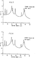
- Tantalum (Ta 181 73 ) has a very useful set of sharp resonances - its cross-section is shown as a function of neutron energy in Figs. 1 and 2. Also shown (Figs. 3-10) for both room temperature and 1000°K are the cross-sections for some other relevant elements - molybdenum, hafnium, tungsten and rhenium.
- Fig. 11 shows the width due to the emission of -rays following neutron capture, as a function of atomic weight of the nuclei. The full width equals + The quantity n varies widely from resonance to resonance but is usually less than . As can be seen is low, ⁇ 60 meV, for nuclei with A ⁇ 180, that is elements Hf, Ta, W and Re,Fig.
- nuclides 150 ⁇ A ⁇ 195 and A > 210 have the narrowest resonances and are therefore particularly suitable for the estimation of temperature.
- isotopes of Hf, Ta, and W which are components of many high temperature alloys, have masses in the range 176 ⁇ A ⁇ 186 and thus narrow resonances which offer the best chance for accurate remote determination of temperature.
- Fig.12 is a schematic diagram of the system layout.
- reference numeral 1 designates a target and moderator to produce neutrons as a result of bombardment by a beam of protons 2
- reference numeral 3 designates a collimator for the neutron beam
- 4 and 5 designate vacuum transport tubes
- 6 designates aperture defining means through which the neutron beam passes to a specimen 7 in an oven 8 evacuated by a vacaum pump 9
- 10 designates a cylindrical He neutron detector (lem in diameter) coupled to signal processing electronic circuitry 11. Exposures to neutrons were taken both with and without a furnace and with and without a thin tantalum foil as a basis for comparison with the significant runs. The significant exposures were:-
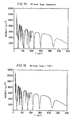
- Fig. 14 shows the effect of comparing two exposures, one with and one without the tantalum foil and plotting its transmission function. Only the tantalum shows up and background everywhere else is unity with 1% fluctuations.
- Fig. 15 shows the absorption with the 8mm Rolls Royce material at room temperature. Many more deep resonances are immediately apparent that are due to the hafnium and tungsten present in addition to the tantalum.
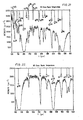
- the data presented in Fig. 16 differs from Fig. 15 only in that the temperature of the Rolls Royce material was held at 730°C. Casual comparison of Figs. 15 and 16 shows little differences. However, the differences are truly there, and can be vividly revealed by dividing the number of neutrons in each microsecond in the first neutron accumulation by those in the second. Clearly, if nothing had changed the result would be unity in all time slots, but what can be seen in this time interval is shown in Fig. 21. Each resonance is replaced by a crater-like shape which approximates in fact to the second derivative of the resonance curve.
- Figs. 18 and 19 show this data with the statistical errors in each time slot displayed.
- the effect of the temperature is considerable with the changes of up to a factor of two in the neutron count occurring due to temperature difference between exposures.
- AT is reduced to ⁇ 5°K.
- Fig. 20 shows the 4eV resonance and the effect of temperature. This resonance is a blend of two lines, one at llllusec delay, due to tantalum, and the second at 1130psec due to tungsten, and this accounts for the different shape of the 'crater' like curves.
- Figs. 21 and 22 show enlarged versions .of part of the raw data from Fig. 15. The various resonances are identified. Note the high Co 59 resonance at ⁇ 200 ⁇ sec delay, and that of W 186 at 530 ⁇ sec. Mn 55 was present also, it is believed, in the oven walls, (124psec). The cadmium was used to filter out low energy neutrons, but also left its mark in the epithermal range.
- the phenomenon of thermal Doppler broadening of nuclear resonances is exploited as a remote and non-invasive temperature probe in neutron transmission radiography measurements.
- the system has the advantage that the broadening of each nuclear resonance line gives the temperature of the material containing that specific nucleus, and not of the other material in the neutron beam. Hence,for example,it may be used to probe the temperature of resonant nuclei in a device surrounded by several centimetres of steel. Further, the temperature of a moving component may be distinguished from a static component of the same composition because of the mechanical Doppler effect. Most elements with Z ⁇ 42 have suitable resonances.
- the resonances in Hf, Ta and W are particularly suitable.
- a set of calibration curves is preparde, each curve being of the ratio of the neutron intensity at a reference temperature to the neutron intensity at a respective different, known temperature, around a resonance.
- the item itself, at an unknown temperature is then used to produce, for the same element and the same resonance, a measurement curve of the ratio of the neutron intensity at the reference temperature to the neutron intensty at the unknown temperature.
- Fig.23 is a longitudinal section of part of the detector; Fig. 24 is a section on X-X in Fig.23; and Fig. 25 is a view of the front of the detector where neutrons enter.
- the detector comprises a pair of aluminium blocks 12 and 13 which are shaped to provide a passageway 14 between them which becomes progressively thinner in the direction of neutron travel.
- the blocks 12 and 13 there are a total of twenty-five transverse cavities 15, twelve of them in one of the blocks and thirteen in the other and alternating with one another as shown in Fig.23.
- each cavity 15 and the passageway 14 there is a rectangular LiI scintillator 16 faced with an aluminium foil 17.
- photomultipliers PMA and PMB for the cavity.
- the shape and size of the entrance opening to neutrons of passageway 14 is defined by adjustable members 18 of boron.
- Reference numerals 19 denote 0-rings for the photomultipliers.
- each scintillator 16 could be about 50mm x 10mm x 1mm in dimensions.
- Fig.26 is a block diagram of electronic signal processing circuitry that may be used in conjunction with the detector of Figs. 23, 24 and 25, for measuring neutron arrival time, which is dependent on neutron energy.
- the circuitry of Fig. 26 is for a respective pair of photomultipliers PMA and PMB, each pair having respective such circuitry.
- the outputs of the photmultipliers PMA and PMB are applied to a 30ns pulse shaper 20 (which adds the two outputs together) and also to respective ones of a pair of 100ns delay circuits 21 and 22.
- the output of pulse shaper 20 is applied to a pair of trigger circuits 23 and 24, the former being set to trigger at about 0.3 Mev detected particle energy (for responding to the presence of a t-ray) and the latter being set to trigger at about 3.5 Mev detected particle energy (for responding to the presence of a neutron).
- the output of trigger circuit 24 is applied to a gate pulse generator 25 and a clock timing circuit 26.
- the output of trigger circuit 23 is applied to a second clock timing circuit 27.
- a 50MHz master clock 28 drives a counter 29 which is gated by pulses on line 30 synchronous with timing pulses for the neutron source, the counter 29 controlling the timing sgnals for the timing circuits 26 and 27.
- the outputs of the clocks 26 and 27 are applied to respective queuing stores 31 an 32 whose outputs are the neutron and y-ray arrival times respectively.
- the generator 25 produces gating pulses G1, G2, G3 and G4 and a "ready" pulse (applied to clock 26).
- the output of delay circuit 21 is applied to gated integrators 31, 32 and 33; the output of delay circuit 22 is applied to gated integrators 34, 35 and 36; and the output of integrators 31 to 36 are applied to analogue to digital converters 37 to 42 respectively.
- the logic pulse following detection of a neutron pulse by trigger circuit 24 sets off the generation of gating pulses Gl, G2 and G3 and reset pulse G4.
- the main pulse is G2 whose length corresponds approximately to the duration of the scintillation. Pulses Gl and G3 are used to monitor the period just before and at the end of the scintillation of the neutron, and thus give a measure of contribution of any background from either another neutron or ⁇ 8 -rays.
- the reset pulse enables the gate pulse generator to accept a further neutron - and may need an additional delay of perhaps 1 ⁇ sec after the end of G2 to cope with the analogue to digital converters etc.
- the generator 25 should also enable the neutron timing circuit to provide a flag to accompany the time of any neutron that gives a trigger.
- the integrators 31 to 36 are gated by pulses Gl, G2 and G3 and accept delayed versions of the photomultiplier pulses.
- the main pulse needs, say, 10 bits; the others, that will be used as corrections, could well be limited to 8 bits.
- the actual output time for the neutron is needed to an accuracy of 0.2 ⁇ sec, but the background corrections need the relative time of the neutron to be detected and possible contaminant neutron or Y-ray(s) with more precision.
- a master clock running at 50MHz is used.
- the period between the neutron source timing pulse and the slowest neutron of interest is ⁇ 2000 ⁇ sec. This is 10 cycles of the master clock - so 18 bits are required.
- queuing store 32 is used.
- time of any neutron preceding the one that is being analysed as it can be responsible for the signals detected in integrators 31 and 34. Times of later neutrons could perhaps be represented by incremental times to save bits.
- the outputs of the two queuing stores contain 108 bits for each neutron.
- the twenty-five scintillators are all viewed independently. Apart from cosmic ray background,no coincidences of note are to be expected from the beam ⁇ -rays. The whole device is thus run as twenty-five independent units, each producing up tol64 bits per neutron.
- the date rate and the total amount of data that would be necessary for some temperature assignment could be handlable using buffers and a video recorder.
- the full device however produces a high mean data rate together with a greater total amount of data for full exposure,involving the detection of around 10 - 10 9 neutrons. Therefore,on line analysis would be appropriate.
- the data could be stored in a two dimensional array, with one component being the position and the second the neutron energy.
- the position is given both by the particular scintillator that gives the trigger and and by the partition of light between the two photomultipliers that are involved, and the total positional information could perhaps be contained in 2000 elements. This allows up to 80 pixels for each detector element - which is all that is worthwhile if the number of photoelectrons detected for each neutron pulse is ⁇ 10 4 .
- the neutron energy is given by the time and needs allowance for the different distances of the separate scintillators from the neutron source. Again this could be contained in 2000 linear elements without too much degradation of energy resolution at the highest energies.
- the effect on a particular photomultiplier signal depends strongly on the duration of the scintillation and the size of the photomultiplier pulse itself.
- the smaller of the two is more vulnerable, but notably the smallest signals that will be accepted correspond to the edge of the field of view. Near the centre of the field of view, the ratio will usually be ⁇ 3:1.
- the corrections to be applied therefore must be adjustable - and probably tailored to the individual scintillators.
- the corrections will depend on the times of the disturbing pulses which are obtainable from the queuing store outputs,and the magnitudes of the signals produced from the gated integrators 31,33,34 and 36. If the computed correction exceeds some threshold, the neutron will have to be rejected.
- Fig.28 is a schematic diagram of a possible form of neutron source.
- a superconducting cyclotron accelerator 43 of about 0.5m in diameter produces H ions which are storable in a storage ring 44 (whose dimensions are about 1.0 x 0.7 m) in which they are constrained electromagnetically.
- H + ions from the ring 44 are applied to a liquid lithium target 45 in a moderator 46 which is a material very rich in hydrogen and about 10cm across.
- a reflector 47 of natural nickel (or Ni 58 ) and around the reflector 47 is a blanket 48 of U 238 . Neutrons exit from an outlet 49.
- the target 45 could be beryllium (or uranium if high energy beams are used - say J 40Mev).
- the moderator material could be dense polyethylene, or a solid unbranched paraffin, or even N 2 H 4 H 2 O.
- storage could be achieved in an arrangement in the outer regions of the accelerator itself.
Landscapes
- Physics & Mathematics (AREA)
- General Physics & Mathematics (AREA)
- Investigating Or Analyzing Materials Using Thermal Means (AREA)
- Measuring Temperature Or Quantity Of Heat (AREA)
- Measurement Of Radiation (AREA)
- Analysing Materials By The Use Of Radiation (AREA)
- Liquid Crystal Substances (AREA)
- Monitoring And Testing Of Nuclear Reactors (AREA)
Priority Applications (1)
| Application Number | Priority Date | Filing Date | Title |
|---|---|---|---|
| AT85309189T ATE62067T1 (de) | 1984-12-18 | 1985-12-17 | Temperaturmessung. |
Applications Claiming Priority (2)
| Application Number | Priority Date | Filing Date | Title |
|---|---|---|---|
| GB8431870 | 1984-12-18 | ||
| GB848431870A GB8431870D0 (en) | 1984-12-18 | 1984-12-18 | Temperature measuring |
Publications (3)
| Publication Number | Publication Date |
|---|---|
| EP0186417A2 true EP0186417A2 (de) | 1986-07-02 |
| EP0186417A3 EP0186417A3 (en) | 1988-03-16 |
| EP0186417B1 EP0186417B1 (de) | 1991-03-27 |
Family
ID=10571337
Family Applications (1)
| Application Number | Title | Priority Date | Filing Date |
|---|---|---|---|
| EP85309189A Expired - Lifetime EP0186417B1 (de) | 1984-12-18 | 1985-12-17 | Temperaturmessung |
Country Status (6)
| Country | Link |
|---|---|
| US (1) | US4839519A (de) |
| EP (1) | EP0186417B1 (de) |
| JP (1) | JPS61191929A (de) |
| AT (1) | ATE62067T1 (de) |
| DE (1) | DE3582321D1 (de) |
| GB (2) | GB8431870D0 (de) |
Cited By (2)
| Publication number | Priority date | Publication date | Assignee | Title |
|---|---|---|---|---|
| EP0251668A3 (en) * | 1986-06-25 | 1988-11-23 | Rolls-Royce Plc | Improvements in temperature measuring |
| WO2015199642A1 (en) | 2014-06-23 | 2015-12-30 | Hewlett-Packard Development Company, L.P. | Printhead assembly |
Families Citing this family (3)
| Publication number | Priority date | Publication date | Assignee | Title |
|---|---|---|---|---|
| JPS6347957A (ja) * | 1986-08-15 | 1988-02-29 | Sumitomo Special Metals Co Ltd | 電子部品用積層基板 |
| GB8711327D0 (en) * | 1987-05-14 | 1987-06-17 | Rolls Royce Plc | Strain measurement |
| EP3462150A1 (de) * | 2017-09-27 | 2019-04-03 | Rolls-Royce Corporation | Temperaturbestimmung unter verwendung von strahlungsdiffraktion |
Family Cites Families (4)
| Publication number | Priority date | Publication date | Assignee | Title |
|---|---|---|---|---|
| DE1154653B (de) * | 1957-05-21 | 1963-09-19 | Licentia Gmbh | Verfahren zur Messung hoher Temperaturen |
| US3051838A (en) * | 1960-04-25 | 1962-08-28 | Astra Inc | Neutron pyrometer |
| US3099745A (en) * | 1960-04-25 | 1963-07-30 | Philips Corp | Temperature measuring method and apparatus |
| US4251724A (en) * | 1978-01-23 | 1981-02-17 | Irt Corporation | Method and apparatus for determination of temperature, neutron absorption cross section and neutron moderating power |
-
1984
- 1984-12-18 GB GB848431870A patent/GB8431870D0/en active Pending
-
1985
- 1985-12-17 AT AT85309189T patent/ATE62067T1/de not_active IP Right Cessation
- 1985-12-17 EP EP85309189A patent/EP0186417B1/de not_active Expired - Lifetime
- 1985-12-17 GB GB08531044A patent/GB2168805B/en not_active Expired
- 1985-12-17 DE DE8585309189T patent/DE3582321D1/de not_active Expired - Lifetime
- 1985-12-18 JP JP60285393A patent/JPS61191929A/ja active Pending
-
1987
- 1987-11-10 US US07/118,969 patent/US4839519A/en not_active Expired - Fee Related
Cited By (3)
| Publication number | Priority date | Publication date | Assignee | Title |
|---|---|---|---|---|
| EP0251668A3 (en) * | 1986-06-25 | 1988-11-23 | Rolls-Royce Plc | Improvements in temperature measuring |
| WO2015199642A1 (en) | 2014-06-23 | 2015-12-30 | Hewlett-Packard Development Company, L.P. | Printhead assembly |
| EP3157752B1 (de) * | 2014-06-23 | 2021-06-23 | Hewlett-Packard Development Company, L.P. | Druckkopfanordnung |
Also Published As
| Publication number | Publication date |
|---|---|
| JPS61191929A (ja) | 1986-08-26 |
| DE3582321D1 (de) | 1991-05-02 |
| EP0186417A3 (en) | 1988-03-16 |
| GB8431870D0 (en) | 1985-01-30 |
| GB8531044D0 (en) | 1986-01-29 |
| ATE62067T1 (de) | 1991-04-15 |
| GB2168805A (en) | 1986-06-25 |
| EP0186417B1 (de) | 1991-03-27 |
| GB2168805B (en) | 1989-01-18 |
| US4839519A (en) | 1989-06-13 |
Similar Documents
| Publication | Publication Date | Title |
|---|---|---|
| Greenwood | Mössbauer spectroscopy | |
| Morgan et al. | Neutron-helium interaction. II. Angular distributions and phase shifts from 0.2 to 7.0 MeV | |
| Swann et al. | Lifetimes of the 6.91-and 7.12-Mev Excited States of O 16 | |
| Coomber | Radiochemical methods in analysis | |
| Bollinger et al. | Boron‐loaded liquid scintillation neutron detectors | |
| Postma et al. | Neutron-resonance capture analysis of materials | |
| EP0186417A2 (de) | Temperaturmessung | |
| Alteholz et al. | A Large acceptance detector system (LADS) for studies of pion absorption | |
| Auman et al. | Neutron total cross sections of the light elements in the energy range 24-60 MeV | |
| GB2199943A (en) | Temperature measurement | |
| Bannerman et al. | The Radiations of RaD | |
| GB2200988A (en) | Temperature measurement | |
| Antman et al. | Improvements of a double focussing iron-core spectrometer for high resolution coincidence and angular correlation measurements | |
| US3470372A (en) | Fog density measurement by x-ray scattering | |
| JPS6171341A (ja) | 成分分析方法 | |
| US3154684A (en) | X-ray analysis system with means to detect only the coherently scattered X-rays | |
| Krick et al. | The 16O (3He, n) 18Ne double-stripping reaction | |
| US3408496A (en) | Alpha ray excited composition analysis | |
| Wetzel | Recoil Broadening of Secondary Transitions in Neutron-Capture Gamma-Ray Cascades | |
| Liu et al. | Test of nuclear decay rate variation due to an antineutrino flux | |
| Ghose | Measurement of absolute differential collision cross sections of Co60 photons for the Compton effect | |
| Fujita et al. | Measurement of Nuclear Inelastic Scattering Cross Section of Thorium-232 for 144keV Si-Filtered Neutrons | |
| Rosen | Neutron resonances in U238 | |
| Pannell | Radioactivity Measurement Techniques | |
| De Saussure et al. | Measurement of the 238U capture cross section for incident neutron energies up to 100 keV |
Legal Events
| Date | Code | Title | Description |
|---|---|---|---|
| PUAI | Public reference made under article 153(3) epc to a published international application that has entered the european phase |
Free format text: ORIGINAL CODE: 0009012 |
|
| AK | Designated contracting states |
Kind code of ref document: A2 Designated state(s): AT BE CH DE FR IT LI LU NL SE |
|
| PUAL | Search report despatched |
Free format text: ORIGINAL CODE: 0009013 |
|
| AK | Designated contracting states |
Kind code of ref document: A3 Designated state(s): AT BE CH DE FR IT LI LU NL SE |
|
| 17P | Request for examination filed |
Effective date: 19880816 |
|
| 17Q | First examination report despatched |
Effective date: 19891006 |
|
| GRAA | (expected) grant |
Free format text: ORIGINAL CODE: 0009210 |
|
| AK | Designated contracting states |
Kind code of ref document: B1 Designated state(s): AT BE CH DE FR IT LI LU NL SE |
|
| PG25 | Lapsed in a contracting state [announced via postgrant information from national office to epo] |
Ref country code: SE Effective date: 19910327 Ref country code: NL Effective date: 19910327 Ref country code: LI Effective date: 19910327 Ref country code: IT Free format text: LAPSE BECAUSE OF FAILURE TO SUBMIT A TRANSLATION OF THE DESCRIPTION OR TO PAY THE FEE WITHIN THE PRESCRIBED TIME-LIMIT;WARNING: LAPSES OF ITALIAN PATENTS WITH EFFECTIVE DATE BEFORE 2007 MAY HAVE OCCURRED AT ANY TIME BEFORE 2007. THE CORRECT EFFECTIVE DATE MAY BE DIFFERENT FROM THE ONE RECORDED. Effective date: 19910327 Ref country code: CH Effective date: 19910327 Ref country code: BE Effective date: 19910327 Ref country code: AT Effective date: 19910327 |
|
| REF | Corresponds to: |
Ref document number: 62067 Country of ref document: AT Date of ref document: 19910415 Kind code of ref document: T |
|
| REF | Corresponds to: |
Ref document number: 3582321 Country of ref document: DE Date of ref document: 19910502 |
|
| ET | Fr: translation filed | ||
| REG | Reference to a national code |
Ref country code: CH Ref legal event code: PL |
|
| NLV1 | Nl: lapsed or annulled due to failure to fulfill the requirements of art. 29p and 29m of the patents act | ||
| K2C3 | Correction of patent specification (complete document) published |
Effective date: 19910327 |
|
| PGFP | Annual fee paid to national office [announced via postgrant information from national office to epo] |
Ref country code: FR Payment date: 19911126 Year of fee payment: 7 |
|
| PG25 | Lapsed in a contracting state [announced via postgrant information from national office to epo] |
Ref country code: LU Free format text: LAPSE BECAUSE OF NON-PAYMENT OF DUE FEES Effective date: 19911231 |
|
| PLBE | No opposition filed within time limit |
Free format text: ORIGINAL CODE: 0009261 |
|
| STAA | Information on the status of an ep patent application or granted ep patent |
Free format text: STATUS: NO OPPOSITION FILED WITHIN TIME LIMIT |
|
| PGFP | Annual fee paid to national office [announced via postgrant information from national office to epo] |
Ref country code: DE Payment date: 19920228 Year of fee payment: 7 |
|
| 26N | No opposition filed | ||
| PG25 | Lapsed in a contracting state [announced via postgrant information from national office to epo] |
Ref country code: FR Effective date: 19930831 |
|
| PG25 | Lapsed in a contracting state [announced via postgrant information from national office to epo] |
Ref country code: DE Effective date: 19930901 |
|
| REG | Reference to a national code |
Ref country code: FR Ref legal event code: ST |