EP0186437A2 - Toronneuse-câbleuse - Google Patents
Toronneuse-câbleuse Download PDFInfo
- Publication number
- EP0186437A2 EP0186437A2 EP85309252A EP85309252A EP0186437A2 EP 0186437 A2 EP0186437 A2 EP 0186437A2 EP 85309252 A EP85309252 A EP 85309252A EP 85309252 A EP85309252 A EP 85309252A EP 0186437 A2 EP0186437 A2 EP 0186437A2
- Authority
- EP
- European Patent Office
- Prior art keywords
- filament
- coils
- stranding machine
- filaments
- coil
- Prior art date
- Legal status (The legal status is an assumption and is not a legal conclusion. Google has not performed a legal analysis and makes no representation as to the accuracy of the status listed.)
- Withdrawn
Links
Images
Classifications
-
- B—PERFORMING OPERATIONS; TRANSPORTING
- B65—CONVEYING; PACKING; STORING; HANDLING THIN OR FILAMENTARY MATERIAL
- B65H—HANDLING THIN OR FILAMENTARY MATERIAL, e.g. SHEETS, WEBS, CABLES
- B65H55/00—Wound packages of filamentary material
- B65H55/04—Wound packages of filamentary material characterised by method of winding
- B65H55/043—Wound packages of filamentary material characterised by method of winding the yarn paying off through the centre of the package
-
- B—PERFORMING OPERATIONS; TRANSPORTING
- B65—CONVEYING; PACKING; STORING; HANDLING THIN OR FILAMENTARY MATERIAL
- B65H—HANDLING THIN OR FILAMENTARY MATERIAL, e.g. SHEETS, WEBS, CABLES
- B65H49/00—Unwinding or paying-out filamentary material; Supporting, storing or transporting packages from which filamentary material is to be withdrawn or paid-out
- B65H49/02—Methods or apparatus in which packages do not rotate
- B65H49/04—Package-supporting devices
- B65H49/06—Package-supporting devices for a single operative package
- B65H49/08—Package-supporting devices for a single operative package enclosing the package
-
- B—PERFORMING OPERATIONS; TRANSPORTING
- B65—CONVEYING; PACKING; STORING; HANDLING THIN OR FILAMENTARY MATERIAL
- B65H—HANDLING THIN OR FILAMENTARY MATERIAL, e.g. SHEETS, WEBS, CABLES
- B65H49/00—Unwinding or paying-out filamentary material; Supporting, storing or transporting packages from which filamentary material is to be withdrawn or paid-out
- B65H49/02—Methods or apparatus in which packages do not rotate
- B65H49/04—Package-supporting devices
- B65H49/14—Package-supporting devices for several operative packages
- B65H49/16—Stands or frameworks
-
- D—TEXTILES; PAPER
- D07—ROPES; CABLES OTHER THAN ELECTRIC
- D07B—ROPES OR CABLES IN GENERAL
- D07B3/00—General-purpose machines or apparatus for producing twisted ropes or cables from component strands of the same or different material
- D07B3/02—General-purpose machines or apparatus for producing twisted ropes or cables from component strands of the same or different material in which the supply reels rotate about the axis of the rope or cable or in which a guide member rotates about the axis of the rope or cable to guide the component strands away from the supply reels in fixed position
- D07B3/06—General-purpose machines or apparatus for producing twisted ropes or cables from component strands of the same or different material in which the supply reels rotate about the axis of the rope or cable or in which a guide member rotates about the axis of the rope or cable to guide the component strands away from the supply reels in fixed position and are spaced radially from the axis of the machine, i.e. basket or planetary-type stranding machine
-
- D—TEXTILES; PAPER
- D07—ROPES; CABLES OTHER THAN ELECTRIC
- D07B—ROPES OR CABLES IN GENERAL
- D07B7/00—Details of, or auxiliary devices incorporated in, rope- or cable-making machines; Auxiliary apparatus associated with such machines
- D07B7/02—Machine details; Auxiliary devices
Definitions
- THIS INVENTION relates to a stranding machine for making multi-stranded cables or robes and the like and particularly to a device for feeding the filaments in such an apparatus.
- filament will be used in this specification as a general term covering strands of any suitable material. Such filaments may of course be multi-stranded themselves.
- wires are helically wound about a central core wire or king wire as it is otherwise known.
- the wires are initially supplied on bobbins or spools, which are rotatably mounted with their axes transverse to the direction of the axis of the cable of the time of manufacture.
- bobbins are mounted in suitable cradles,. generally one behind the other.
- the bobbins are mounted in a rotating device and the wires, except for the core wire, pass through guide apertures around the periphery of an annular guide. As the device rotates the annular guide winds the wires around the central core wire in a helical manner as described above.
- An object of this invention is to provide apparatus for making cables of the type mentioned above, which apparatus has the facility of working at higher speeds than known types of apparatus and has a reduced filament loading time.
- a stranding machine for making multi-stranded cables or the like including a device for feeding filaments comprising support means for supporting a plurality of coils of filament wherein the axes of the coils are parallel to each other, the arrangement being such that the coils are rotatable about an axis parallel to those of the coils.
- the support means may comprise at least two spaced apart support devices such as, for example, appropriately shaped recesses.
- the machine may include at least two outer filament coil support devices arranged about a central axis of rotation; filament guides for guiding filaments emerging from the filament coil support devices; means for rotating the coil support devices and filament guides in unision about said axis and cable tensioning means for maintaining tension on the cable and filaments during manufacture of the cable.
- the cable tensioning means may comprise a friction pulley and a cable take-up device.
- the apparatus includes a central support device for a core filament.
- the filament coil supports are of elongated tubular configuration having filament feed orifices at the ends thereof adjacent the filament guides and having loading orifices at their opposite ends.
- One embodiment of the invention may include a pre-forming head, a sizing die, and past forming rolls.
- the machine may include filament coil cassettes for location in the coil support devices.
- the cassettes each comprise a tubular member for housing a filament coil, a front end closure member having a feeding orifice therethrough, and a pay-off device for insertion in the rear of the filament coil, the pay off device defining a passage through which the filament passes.
- a method of manufacturing a multi-stranded cable comprising the steps of mounting coils of filament on a rotatable assembly and withdrawing the filaments together as the assembly is rotated, wherein the axes of the coils are parallel to the axis of rotation of said rotatable assembly.
- one filament from the assembly forms a king filament, and the remaining filaments are wound onto the king filament.
- said coils comprise at least three equi-spaced coils which provide filaments that form the outer filaments of the cable.
- the coil support devices all have their axes parallel to each other, and parallel to the axis of the cable that is to be manufactured.
- the support devices are mounted for rotation about an axis parallel to the axes of the support devices.
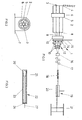
- the support devices 2 are supported in a suitable ring bearing 5 which in turn is located in a bearing mounting 6 adapted to be fixed to a support surface 7 such as a floor.
- the support devices 2 and 3 are open at their rear ends 4 and closed at their forward ends 8 except for centrally located filament feed orifices (not shown).
- the support devices 2 and 3 are supported by an elongated tubular member 9 which encompasses the central support device 3 and projects coaxially therefrom. Near its free end this member 9 is supported in a ring bearing and mounting 10 similar to the mounting 6 near the rear end 4 of the support devices 2 and 3.
- the two mountings 6 and 10 thus enable the support devices 2 and 3 and the member 9 to rotate about an axis which is the same as that of the support device 3.
- a guide member I including filament guides and a filament pre-forming head 12 of the type known in the art.
- the pre-forming head is provided with pre-forming guides 13.
- i Means for rotating the support devices 2 and 3, the tubular member 9 and the guide member I is provided, for example in the form of an electrical motor and gear box.
- a suitable drive mechanism for connecting the drive means to the tubular member 9 is provided.
- the drawings of the specification indicate a simple pulley 14 on the tubular member 9 between the mounting 10 and the guide member II.
- the pulley 14 is driven by way of a belt 15.
- other methods such as direct drive mechanisms or sprockets and chains may also be used.
- Adjacent the guide member and preforming head 12 is a sizing die 16 which is followed by horizontal and vertical post forming rolls 17 and 18 respectively.
- a cable tensioning means 19 Spaced a short distance from the vertical rolls is a cable tensioning means 19 which comprises a friction pulley 20 around which the cable is passed.
- This friction pulley also includes a drive means and is well known in the art of cable manufacture.
- a cable take up drum 21 is located adjacent the tensioning device 19.
- the apparatus I is adapted for use with elongate coils of suitable wire instead of the normally used bobbins.
- Such coils are of an elongated cylindrical form, have a plurality of layers, and are hollow in the centre. This hollow centre enables the coils to be unwound from the inside, or to be unwound from one end with the filament being unwound from the coil passing through the hollow centre of the coil.
- the coils are inserted into the support devices 2 and 3 so that the dres of the coils are parallel with each other and also parallel with the axis of the cable to be manufactured.
- the wire from each coil is then fed from the rear of the coil, over and through a suitable "pay off" member, through the centre of the coil through the appropriate filament feed orifice, and via ' ie appropriate guide of the guide member I I to the sizing die 16.
- the rotatable part of the apparatus is then rotated and the coils thus rotate obout an axis parallel to the axes of the coils.
- the wires from the outer support devices 2 are wound around the core wire from the central support device 3 thus forming a cable.
- the cable is tensioned by the tensioning device 19 and is thus continually drawn out past the member 9 and the guide member 11.
- the manufactured cable is wound onto the drum 21.
- each cassette 22 may comprise an elongated tubular housing 23 substantially closed at the front end except for a feeding orifice in the front end closure member 24.
- the rear end of the cassette is open.
- the cassette contains a coil 25 of wire. Feeding of the wire from the coil 25 is from the rear thereof and to enable this to be effected a pay-off device 26 is located in the rear end of each coil 25.
- This device 26 is a substantially pear shaped element having an axial bore therethrough. The greatest diameter of the pay-off device 26 is less than the inner diameter of the cassette.
- the wire thus passes from the end of the coil, over a smooth rounded rear surface of the pay-off device 26 and through the bore therethrough for the passage of the wire 27 through the centre of the coil. As the coil of wire is consumed, so the pay-off device will move towards the closed end of the cassette.
- the apparatus has advantages over apparatus known in the art in that it is easier to load than the normal spool or bobbin type of apparatus since the cassettes can be mounted in position relatively rapidly. It has been found that the coils feed the wire faster than in a comparable prior art device. It is to be noted that, in contrast to the prior art arrangement, the coils do not rotate about their own axes as the wire is paid out. Thus the coils do not have angular momentum about their own axes, but only about the one axis of rotation of the described apparatus. Also because of its smaller diameter than the prior art devices the apparatus may be rotated at a higher speed than known apparatuses, thus increasing the speed of manufacture of the cable.
- the apparatus may have other forms and configurations.
- the coil support devices could be arranged one behind the other.
- the apparatus may be used in the manufacture of other products than wire cables, such as cables made from other filaments.
- a loading device could be provided which may comprise a plurality of tubes of similar configuration to the coil support devices.
- the cassettes could be pre-loaded into the tubes.
- the spent cassettes may be ejected or removed and then the tubes may be aligned with the coil support devices.
- the fresh cassettes may then simply be pushed, using a suitable apparatus into the coil support devices, thus ensuring a rapid loading of the apparatus.
Landscapes
- Engineering & Computer Science (AREA)
- Textile Engineering (AREA)
- Wire Processing (AREA)
- Ropes Or Cables (AREA)
- Paper (AREA)
- Vending Machines For Individual Products (AREA)
- Automatic Disk Changers (AREA)
Applications Claiming Priority (2)
| Application Number | Priority Date | Filing Date | Title |
|---|---|---|---|
| ZA849847 | 1984-12-18 | ||
| ZA849847 | 1984-12-18 |
Publications (2)
| Publication Number | Publication Date |
|---|---|
| EP0186437A2 true EP0186437A2 (fr) | 1986-07-02 |
| EP0186437A3 EP0186437A3 (fr) | 1987-08-19 |
Family
ID=25577655
Family Applications (1)
| Application Number | Title | Priority Date | Filing Date |
|---|---|---|---|
| EP85309252A Withdrawn EP0186437A3 (fr) | 1984-12-18 | 1985-12-18 | Toronneuse-câbleuse |
Country Status (9)
| Country | Link |
|---|---|
| US (1) | US4677816A (fr) |
| EP (1) | EP0186437A3 (fr) |
| JP (1) | JPS61186588A (fr) |
| AU (1) | AU5144185A (fr) |
| DK (1) | DK590585A (fr) |
| ES (1) | ES8705546A1 (fr) |
| FI (1) | FI855067L (fr) |
| NO (1) | NO855114L (fr) |
| PT (1) | PT81707B (fr) |
Cited By (1)
| Publication number | Priority date | Publication date | Assignee | Title |
|---|---|---|---|---|
| CN104174671A (zh) * | 2014-07-23 | 2014-12-03 | 贵州钢绳股份有限公司 | 压实股专用连续生产线设备 |
Families Citing this family (4)
| Publication number | Priority date | Publication date | Assignee | Title |
|---|---|---|---|---|
| JPH02127581A (ja) * | 1988-11-05 | 1990-05-16 | Kanai Hiroyuki | スチールコードの製造方法およびその装置 |
| JPH0721597Y2 (ja) * | 1993-11-16 | 1995-05-17 | トクセン工業株式会社 | スチールコードの製造装置 |
| US6378283B1 (en) * | 2000-05-25 | 2002-04-30 | Helix/Hitemp Cables, Inc. | Multiple conductor electrical cable with minimized crosstalk |
| CN114852308B (zh) * | 2022-04-12 | 2022-12-27 | 山东固丝德夫金属制品有限公司 | 一种弯曲性能高的船用钢丝绳 |
Family Cites Families (14)
| Publication number | Priority date | Publication date | Assignee | Title |
|---|---|---|---|---|
| US3097472A (en) * | 1963-07-16 | Apparatus for making rope strand | ||
| FR581022A (fr) * | 1924-05-02 | 1924-11-21 | E Van Merisse | Machine à faire le câblé |
| US1943086A (en) * | 1932-07-02 | 1934-01-09 | Gen Cable Corp | Electrical cable and method of manufacture |
| GB534433A (en) * | 1940-02-22 | 1941-03-06 | Deichsel A Magyar Aceldrot Dro | Improvements in machines for the manufacture of wire rope or cable |
| GB706971A (en) * | 1950-01-27 | 1954-04-07 | Standard Telephones Cables Ltd | Improvements in or relating to the production of multi conductor cables |
| US2886939A (en) * | 1953-12-02 | 1959-05-19 | Wool Ind Res Association | Apparatus for inserting twist into a twistless sliver simultaneously with its feed into a drafting head for twisted slivers |
| US2976669A (en) * | 1955-07-14 | 1961-03-28 | Celanese Corp | Apparatus for the production of cables |
| US3360919A (en) * | 1965-10-08 | 1968-01-02 | Anaconda Wire & Cable Co | Stranding apparatus |
| US4073127A (en) * | 1977-02-07 | 1978-02-14 | Belden Corporation | Twining and cabling system |
| DE3206932A1 (de) * | 1980-09-18 | 1983-09-15 | Werner 6349 Hörbach Henrich | Vorrichtung zum verseilen von strangfoermigem gut |
| DE3035208A1 (de) * | 1980-09-18 | 1982-04-22 | Werner 6349 Hörbach Henrich | Vorrichtung zum verseilen von draehten |
| DE3221369A1 (de) * | 1982-06-05 | 1983-12-08 | kabelmetal electro GmbH, 3000 Hannover | Verseilvorrichtung zur herstellung von langgestrecktem gut |
| DE3320250A1 (de) * | 1982-10-21 | 1984-04-26 | Werner 6349 Hörbach Henrich | Verfahren zum weiterverarbeiten von mit hilfe eines flyers aufgewickeltem strangfoermigen gut |
| IT1160833B (it) * | 1983-03-24 | 1987-03-11 | Pirelli Cavi Spa | Perfezionamento a procedimento ed impianto per la riunione di cavi elettrici multipolari |
-
1985
- 1985-12-16 US US06/809,330 patent/US4677816A/en not_active Expired - Fee Related
- 1985-12-18 AU AU51441/85A patent/AU5144185A/en not_active Abandoned
- 1985-12-18 NO NO855114A patent/NO855114L/no unknown
- 1985-12-18 DK DK590585A patent/DK590585A/da not_active Application Discontinuation
- 1985-12-18 JP JP60283228A patent/JPS61186588A/ja active Pending
- 1985-12-18 ES ES550129A patent/ES8705546A1/es not_active Expired
- 1985-12-18 EP EP85309252A patent/EP0186437A3/fr not_active Withdrawn
- 1985-12-18 FI FI855067A patent/FI855067L/fi not_active IP Right Cessation
- 1985-12-18 PT PT81707A patent/PT81707B/pt unknown
Cited By (1)
| Publication number | Priority date | Publication date | Assignee | Title |
|---|---|---|---|---|
| CN104174671A (zh) * | 2014-07-23 | 2014-12-03 | 贵州钢绳股份有限公司 | 压实股专用连续生产线设备 |
Also Published As
| Publication number | Publication date |
|---|---|
| AU5144185A (en) | 1986-06-26 |
| DK590585D0 (da) | 1985-12-18 |
| JPS61186588A (ja) | 1986-08-20 |
| NO855114L (no) | 1986-06-19 |
| PT81707B (en) | 1987-01-06 |
| ES8705546A1 (es) | 1987-05-16 |
| DK590585A (da) | 1986-06-19 |
| EP0186437A3 (fr) | 1987-08-19 |
| FI855067A7 (fi) | 1986-06-19 |
| ES550129A0 (es) | 1987-05-16 |
| FI855067A0 (fi) | 1985-12-18 |
| US4677816A (en) | 1987-07-07 |
| PT81707A (en) | 1986-01-02 |
| FI855067L (fi) | 1986-06-19 |
Similar Documents
| Publication | Publication Date | Title |
|---|---|---|
| US3396522A (en) | Stranding machine | |
| EP0138731A2 (fr) | Câble métallique | |
| CA2201849A1 (fr) | Appareil servant a fabriquer des fils torsades | |
| US4566261A (en) | Metallic cable and apparatus for manufacturing the same | |
| CA1290995C (fr) | Dispositif et methode de fabrication de corde metallique toronnee | |
| SK37598A3 (en) | Process and device for the simultaneous winding of a multi-wire coil with several wires and/or the simultaneous unwinding of the wires from such a wound multi-wire coil for subsequent stranding | |
| US5400579A (en) | Apparatus and method for the manufacture of telephone cables | |
| KR950008366B1 (ko) | 강철코드의 제조방법 및 그 장치 | |
| EP0186437A2 (fr) | Toronneuse-câbleuse | |
| HU181317B (en) | Equipment for preparing electric cables | |
| US4300339A (en) | System for stranding and cabling elongate filaments | |
| US3726074A (en) | Method and apparatus for manufacture of strands and cables | |
| EP0094336B1 (fr) | Procédé et appareil pour la fabrication de câblés métalliques | |
| GB1603664A (en) | Fly-off strander | |
| US4384447A (en) | Wire stranding apparatus | |
| US4570428A (en) | Twin track buncher | |
| US4509317A (en) | Apparatus and method for making metallic cord | |
| US3302380A (en) | Cord twister | |
| JP3595514B2 (ja) | 撚線機 | |
| JPS63282386A (ja) | 一重及び多重の鋼線ストランドの製造方法及びその装置 | |
| AU589572B2 (en) | Double twist bow buncher | |
| EP0409621A1 (fr) | Appareil d'assemblage de câbles | |
| FI66029B (fi) | Anordning foer framstaellning av en flertraodsstraeng eller enabel | |
| JPS59124655A (ja) | フライヤ−を用いて巻きつけられた線状物体をさらに加工するための方法 | |
| JPH0636630A (ja) | 電気的又は光学的な伝達部材用の撚り装置並びにこのような伝達部材を撚るための方法 |
Legal Events
| Date | Code | Title | Description |
|---|---|---|---|
| PUAI | Public reference made under article 153(3) epc to a published international application that has entered the european phase |
Free format text: ORIGINAL CODE: 0009012 |
|
| AK | Designated contracting states |
Kind code of ref document: A2 Designated state(s): AT BE DE FR GB IT LU NL SE |
|
| PUAL | Search report despatched |
Free format text: ORIGINAL CODE: 0009013 |
|
| AK | Designated contracting states |
Kind code of ref document: A3 Designated state(s): AT BE DE FR GB IT LU NL SE |
|
| STAA | Information on the status of an ep patent application or granted ep patent |
Free format text: STATUS: THE APPLICATION IS DEEMED TO BE WITHDRAWN |
|
| 18D | Application deemed to be withdrawn |
Effective date: 19880420 |
|
| RIN1 | Information on inventor provided before grant (corrected) |
Inventor name: WOXHOLT, STANLEY |