EP0186449A1 - Transducteurs sous-marins - Google Patents
Transducteurs sous-marins Download PDFInfo
- Publication number
- EP0186449A1 EP0186449A1 EP85309276A EP85309276A EP0186449A1 EP 0186449 A1 EP0186449 A1 EP 0186449A1 EP 85309276 A EP85309276 A EP 85309276A EP 85309276 A EP85309276 A EP 85309276A EP 0186449 A1 EP0186449 A1 EP 0186449A1
- Authority
- EP
- European Patent Office
- Prior art keywords
- transducer
- component
- transducer according
- polyurethane
- encapsulation
- Prior art date
- Legal status (The legal status is an assumption and is not a legal conclusion. Google has not performed a legal analysis and makes no representation as to the accuracy of the status listed.)
- Withdrawn
Links
- 238000005538 encapsulation Methods 0.000 claims abstract description 13
- 229920002635 polyurethane Polymers 0.000 claims abstract description 10
- 239000004814 polyurethane Substances 0.000 claims abstract description 10
- 229910052751 metal Inorganic materials 0.000 claims description 7
- 239000002184 metal Substances 0.000 claims description 7
- 239000000853 adhesive Substances 0.000 claims description 5
- 230000001070 adhesive effect Effects 0.000 claims description 5
- 230000007717 exclusion Effects 0.000 claims description 2
- 229920001971 elastomer Polymers 0.000 claims 1
- 239000000806 elastomer Substances 0.000 claims 1
- XLYOFNOQVPJJNP-UHFFFAOYSA-N water Substances O XLYOFNOQVPJJNP-UHFFFAOYSA-N 0.000 abstract description 9
- 229910000831 Steel Inorganic materials 0.000 abstract description 3
- 239000010959 steel Substances 0.000 abstract description 3
- 230000001052 transient effect Effects 0.000 abstract description 3
- 230000008878 coupling Effects 0.000 abstract description 2
- 238000010168 coupling process Methods 0.000 abstract description 2
- 238000005859 coupling reaction Methods 0.000 abstract description 2
- 239000011347 resin Substances 0.000 description 5
- 229920005989 resin Polymers 0.000 description 5
- 239000000919 ceramic Substances 0.000 description 4
- 238000005259 measurement Methods 0.000 description 4
- 230000035945 sensitivity Effects 0.000 description 4
- 238000005273 aeration Methods 0.000 description 3
- 239000013078 crystal Substances 0.000 description 3
- RYGMFSIKBFXOCR-UHFFFAOYSA-N Copper Chemical compound [Cu] RYGMFSIKBFXOCR-UHFFFAOYSA-N 0.000 description 2
- 239000004020 conductor Substances 0.000 description 2
- 229910052802 copper Inorganic materials 0.000 description 2
- 239000010949 copper Substances 0.000 description 2
- 238000005260 corrosion Methods 0.000 description 2
- 230000007797 corrosion Effects 0.000 description 2
- 238000001514 detection method Methods 0.000 description 2
- 238000010586 diagram Methods 0.000 description 2
- 238000006073 displacement reaction Methods 0.000 description 2
- 210000004907 gland Anatomy 0.000 description 2
- 238000004519 manufacturing process Methods 0.000 description 2
- 239000000463 material Substances 0.000 description 2
- 238000000034 method Methods 0.000 description 2
- 230000001902 propagating effect Effects 0.000 description 2
- 239000000565 sealant Substances 0.000 description 2
- 238000012360 testing method Methods 0.000 description 2
- PNEYBMLMFCGWSK-UHFFFAOYSA-N Alumina Chemical compound [O-2].[O-2].[O-2].[Al+3].[Al+3] PNEYBMLMFCGWSK-UHFFFAOYSA-N 0.000 description 1
- 241001465754 Metazoa Species 0.000 description 1
- ZOKXTWBITQBERF-UHFFFAOYSA-N Molybdenum Chemical compound [Mo] ZOKXTWBITQBERF-UHFFFAOYSA-N 0.000 description 1
- 230000002411 adverse Effects 0.000 description 1
- 230000004888 barrier function Effects 0.000 description 1
- 239000003795 chemical substances by application Substances 0.000 description 1
- KPLQYGBQNPPQGA-UHFFFAOYSA-N cobalt samarium Chemical compound [Co].[Sm] KPLQYGBQNPPQGA-UHFFFAOYSA-N 0.000 description 1
- 238000004891 communication Methods 0.000 description 1
- 230000006835 compression Effects 0.000 description 1
- 238000007906 compression Methods 0.000 description 1
- 230000000694 effects Effects 0.000 description 1
- 239000011521 glass Substances 0.000 description 1
- 239000004519 grease Substances 0.000 description 1
- 230000002706 hydrostatic effect Effects 0.000 description 1
- 239000003112 inhibitor Substances 0.000 description 1
- 238000007689 inspection Methods 0.000 description 1
- 238000002955 isolation Methods 0.000 description 1
- 239000000203 mixture Substances 0.000 description 1
- 238000012986 modification Methods 0.000 description 1
- 230000004048 modification Effects 0.000 description 1
- 229910052750 molybdenum Inorganic materials 0.000 description 1
- 239000011733 molybdenum Substances 0.000 description 1
- 238000000465 moulding Methods 0.000 description 1
- 229920000573 polyethylene Polymers 0.000 description 1
- 239000002243 precursor Substances 0.000 description 1
- 238000002360 preparation method Methods 0.000 description 1
- 230000004044 response Effects 0.000 description 1
- 229910000938 samarium–cobalt magnet Inorganic materials 0.000 description 1
- 238000007789 sealing Methods 0.000 description 1
- 238000005728 strengthening Methods 0.000 description 1
Images

Classifications
-
- G—PHYSICS
- G10—MUSICAL INSTRUMENTS; ACOUSTICS
- G10K—SOUND-PRODUCING DEVICES; METHODS OR DEVICES FOR PROTECTING AGAINST, OR FOR DAMPING, NOISE OR OTHER ACOUSTIC WAVES IN GENERAL; ACOUSTICS NOT OTHERWISE PROVIDED FOR
- G10K11/00—Methods or devices for transmitting, conducting or directing sound in general; Methods or devices for protecting against, or for damping, noise or other acoustic waves in general
- G10K11/002—Devices for damping, suppressing, obstructing or conducting sound in acoustic devices
-
- B—PERFORMING OPERATIONS; TRANSPORTING
- B06—GENERATING OR TRANSMITTING MECHANICAL VIBRATIONS IN GENERAL
- B06B—METHODS OR APPARATUS FOR GENERATING OR TRANSMITTING MECHANICAL VIBRATIONS OF INFRASONIC, SONIC, OR ULTRASONIC FREQUENCY, e.g. FOR PERFORMING MECHANICAL WORK IN GENERAL
- B06B1/00—Methods or apparatus for generating mechanical vibrations of infrasonic, sonic, or ultrasonic frequency
- B06B1/02—Methods or apparatus for generating mechanical vibrations of infrasonic, sonic, or ultrasonic frequency making use of electrical energy
- B06B1/06—Methods or apparatus for generating mechanical vibrations of infrasonic, sonic, or ultrasonic frequency making use of electrical energy operating with piezoelectric effect or with electrostriction
- B06B1/0644—Methods or apparatus for generating mechanical vibrations of infrasonic, sonic, or ultrasonic frequency making use of electrical energy operating with piezoelectric effect or with electrostriction using a single piezoelectric element
- B06B1/0651—Methods or apparatus for generating mechanical vibrations of infrasonic, sonic, or ultrasonic frequency making use of electrical energy operating with piezoelectric effect or with electrostriction using a single piezoelectric element of circular shape
Definitions
- This invention relates to transducers used for the sensing of transient elastic waves in metallic components and in particular to the detection of elastic waves originating from micro displacements associated with subcritical crack growth in the steel weldments of offshore structures below water.
- transducers for such applications have not shown such good directionality and sensitivity as to warrant the analysis of elastic waves emanating from micro-displacements in underwater structures nor have they shown sufficient strength of attachment to be usable throughout the year in the 'splash zone'.
- ultrasonic methods of crack detection generally require extensive preparation of the structure and equipment in setting up transducers for single localised measurements and have proven impractical for underwater inspection of such structures.
- This invention seeks to improve these features so as to make acoustic emission measurements below water on offshore structures viable.
- a transducer for sensing elastic waves in a metal component, having a sensing head adapted to be coupled to the component, which is shielded from noise arriving in directions other than from the component, by an elastomeric encapsulation.
- the transducer is provided with a flexible skirt for the exclusion of noise through gaps between the transducer and the component.
- the transducer is provided with one or more magnets for attaching it to the component.
- an adhesive is provided between the transducer and the component, the adhesive also acting as an acoustic couplant.
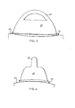
- the transducer shown comprises:
- a transducer is shown attached to a metal tube (27) such as a leg or member, in the shape of a cylinder, of an offshore oil production platform.
- a metal tube such as a leg or member, in the shape of a cylinder, of an offshore oil production platform.
- an underwater curing resin which acts as a sealant, adhesive, couplant and corrosion inhibitor, is extruded onto the front face of the transducer. This is best done in the dry but a hole can be provided through the polyurethane encapsulation to the front face for injecting the resin underwater while the front face is temporarily covered by a transparent polythene plate strapped to the transducer.
- the transducer is then placed on the clean metal such that its major axis is parallel to the major axis of the cylinder as shown. The magnets hold the transducer securely to the tube and once the resin has set, the join is virtually permanent even in severe waves.
- the electric signal produced by the crystal is amplified by the low noise, line-drive preamplifier which is standard in the art and the signal is conducted away by the cable (15). Power for the preamplifier is supplied by the same signal conductor and screen of the cable.
- a suitable control signal from the cable can switch the transducer to test mode whereby acoustic signals can be emitted from the crystal (1) to be detected by other transducers in known manner.
- the shoe (3) protrudes about 1 mm beyond the flat front face of the transducer facilitating a strong positive pressure on the shoe by the structure due to elastic resilience of the polyurethane molding when the transducer is pulled onto the surface of the tube by the magnets (19).
- the resin couplant fills pitholes in the surface of the metal under and around the ceramic further improving the acoustic coupling. Resin is more practical than conventional grease for this purpose and proves to be a better couplant.
- the polyurethane encapsulation (23) gives good acoustic shielding of the sensor from water borne compressional waves at the operating frequency usually greater than 50 kHz.
- the skirt (25) forms an enclosure for the contact face of the transducer and the structure below, further shielding against water borne noise, and the sealant aids this function.
- the elastomeric encapsulation (the polyurethane) be provided with additional means to imp_rove acoustic shielding. This may be accomplished by including layers of acoustic barrier material within the encapsulation.
- a very convenient method of emparting high acoustic shielding properties to the polyurethane is to inject gas into it during manufacturing (e.g. by aeration) so that it cures as a closed cell structure, the cells being surrounded by relatively thick walls to retain mechanical integrity in use under water.
- the bubbles (the closed cells) have average diameters of about 0.25 mm separated about 3 mm apart. (These are of course approximate figures as the cells are randomly dispersed in the encapsulation).
- Aeration may be achieved by extruding degassed polyurethane precursor and curing agent into a mixing chamber and introducing air under pressure therein. The aerated mixture is then forced into a mould of appropriate shape to cure. The degree of aeration and cell size may be controlled by trial and error by varying the air pressure and the rate of flow of materials into the mixing chamber and the mould.
Landscapes
- Engineering & Computer Science (AREA)
- Mechanical Engineering (AREA)
- Physics & Mathematics (AREA)
- Acoustics & Sound (AREA)
- Multimedia (AREA)
- Transducers For Ultrasonic Waves (AREA)
- Length Measuring Devices Characterised By Use Of Acoustic Means (AREA)
- Investigating Or Analyzing Materials By The Use Of Ultrasonic Waves (AREA)
Applications Claiming Priority (2)
| Application Number | Priority Date | Filing Date | Title |
|---|---|---|---|
| GB848432508A GB8432508D0 (en) | 1984-12-21 | 1984-12-21 | Underwater transducers |
| GB8432508 | 1984-12-21 |
Publications (1)
| Publication Number | Publication Date |
|---|---|
| EP0186449A1 true EP0186449A1 (fr) | 1986-07-02 |
Family
ID=10571650
Family Applications (1)
| Application Number | Title | Priority Date | Filing Date |
|---|---|---|---|
| EP85309276A Withdrawn EP0186449A1 (fr) | 1984-12-21 | 1985-12-19 | Transducteurs sous-marins |
Country Status (6)
| Country | Link |
|---|---|
| US (1) | US4665750A (fr) |
| EP (1) | EP0186449A1 (fr) |
| JP (1) | JPS61204560A (fr) |
| DK (1) | DK590485A (fr) |
| GB (1) | GB8432508D0 (fr) |
| NO (1) | NO855150L (fr) |
Cited By (3)
| Publication number | Priority date | Publication date | Assignee | Title |
|---|---|---|---|---|
| GB2185817A (en) * | 1984-05-29 | 1987-07-29 | Nissan Motor | Ultrasonic rangefinder |
| FR2623683A1 (fr) * | 1987-11-19 | 1989-05-26 | Krupp Atlas Elektronik Gmbh | Element transducteur |
| DE102006008718A1 (de) * | 2006-02-24 | 2007-08-30 | Volkswagen Ag | Ultraschallsensormodul |
Families Citing this family (18)
| Publication number | Priority date | Publication date | Assignee | Title |
|---|---|---|---|---|
| FI901359A0 (fi) * | 1988-07-25 | 1990-03-19 | Inst Elektroswarki Patona | Transduktor foer registrering av akustiska emissionsignaler. |
| US5992077A (en) * | 1998-03-18 | 1999-11-30 | The United States Of America As Represented By The Secretary Of The Navy | Nose cone and method for acoustically shielding an underwater vehicle sonar array |
| KR100754719B1 (ko) | 2003-09-22 | 2007-09-03 | 김형윤 | 구조물의 건전성 감시용 센서 및 시스템 |
| US7729035B2 (en) * | 2003-09-22 | 2010-06-01 | Hyeung-Yun Kim | Acousto-optic modulators for modulating light signals |
| US7536912B2 (en) | 2003-09-22 | 2009-05-26 | Hyeung-Yun Kim | Flexible diagnostic patches for structural health monitoring |
| KR100772286B1 (ko) * | 2003-09-22 | 2007-11-01 | 김형윤 | 구조물의 건전성 감시용 센서 및 시스템 |
| US7322244B2 (en) * | 2003-09-22 | 2008-01-29 | Hyeung-Yun Kim | Interrogation system for active monitoring of structural conditions |
| KR100754718B1 (ko) | 2003-09-22 | 2007-09-03 | 김형윤 | 구조물의 건전성 감시용 센서 및 시스템 |
| US7668665B2 (en) * | 2003-09-22 | 2010-02-23 | Advanced Structure Monitoring, Inc. | Methods of networking interrogation devices for structural conditions |
| AU2004277167A1 (en) * | 2003-09-22 | 2005-04-07 | Kim Hyeung-Yun | Methods for monitoring structural health conditions |
| US7325456B2 (en) * | 2003-09-22 | 2008-02-05 | Hyeung-Yun Kim | Interrogation network patches for active monitoring of structural health conditions |
| US20090157358A1 (en) * | 2003-09-22 | 2009-06-18 | Hyeung-Yun Kim | System for diagnosing and monitoring structural health conditions |
| US7536911B2 (en) * | 2003-09-22 | 2009-05-26 | Hyeung-Yun Kim | Diagnostic systems of optical fiber coil sensors for structural health monitoring |
| US8402840B2 (en) * | 2009-06-09 | 2013-03-26 | Expro Meters, Inc. | Ultrasonic fluid flow meter housing with acoustically matched base |
| CN102032969B (zh) * | 2010-11-05 | 2012-02-29 | 西安近代化学研究所 | 一种水中爆炸压力测量传感器 |
| US20150247778A1 (en) * | 2012-05-02 | 2015-09-03 | Siemens Aktiengesellschaft | Method for monitoring damage to a shaft |
| WO2014090301A1 (fr) * | 2012-12-12 | 2014-06-19 | Aktiebolaget Skf | Coupleur et système de coupleur, transducteur, et composant de construction |
| GB2526566A (en) | 2014-05-28 | 2015-12-02 | Skf Ab | Couplant and arrangement of couplant, transducer, and construction component |
Citations (2)
| Publication number | Priority date | Publication date | Assignee | Title |
|---|---|---|---|---|
| DE2526817A1 (de) * | 1974-06-17 | 1976-01-02 | Gen Electric Canada | Wandlerkopplung |
| GB2089617A (en) * | 1980-12-16 | 1982-06-23 | Micro Pure Systems Inc | Ultrasonic sensing |
Family Cites Families (4)
| Publication number | Priority date | Publication date | Assignee | Title |
|---|---|---|---|---|
| US3378705A (en) * | 1966-01-26 | 1968-04-16 | Budd Co | Ultrasonic transducers and method of manufacture thereof |
| US3529465A (en) * | 1968-02-23 | 1970-09-22 | Claus Kleesattel | Fatigue testing and apparatus therefor |
| US3921442A (en) * | 1973-11-28 | 1975-11-25 | Automation Ind Inc | Acoustic couplant for use with an ultrasonic search unit |
| US4461177A (en) * | 1982-07-28 | 1984-07-24 | Dunegan Corporation | Acoustic emission transducer package |
-
1984
- 1984-12-21 GB GB848432508A patent/GB8432508D0/en active Pending
-
1985
- 1985-12-17 US US06/809,697 patent/US4665750A/en not_active Expired - Fee Related
- 1985-12-18 DK DK590485A patent/DK590485A/da not_active Application Discontinuation
- 1985-12-19 EP EP85309276A patent/EP0186449A1/fr not_active Withdrawn
- 1985-12-19 NO NO855150A patent/NO855150L/no unknown
- 1985-12-21 JP JP60289098A patent/JPS61204560A/ja active Pending
Patent Citations (2)
| Publication number | Priority date | Publication date | Assignee | Title |
|---|---|---|---|---|
| DE2526817A1 (de) * | 1974-06-17 | 1976-01-02 | Gen Electric Canada | Wandlerkopplung |
| GB2089617A (en) * | 1980-12-16 | 1982-06-23 | Micro Pure Systems Inc | Ultrasonic sensing |
Cited By (4)
| Publication number | Priority date | Publication date | Assignee | Title |
|---|---|---|---|---|
| GB2185817A (en) * | 1984-05-29 | 1987-07-29 | Nissan Motor | Ultrasonic rangefinder |
| FR2623683A1 (fr) * | 1987-11-19 | 1989-05-26 | Krupp Atlas Elektronik Gmbh | Element transducteur |
| DE102006008718A1 (de) * | 2006-02-24 | 2007-08-30 | Volkswagen Ag | Ultraschallsensormodul |
| DE102006008718B4 (de) * | 2006-02-24 | 2017-05-18 | Volkswagen Ag | Ultraschallsensormodul |
Also Published As
| Publication number | Publication date |
|---|---|
| GB8432508D0 (en) | 1985-02-06 |
| DK590485D0 (da) | 1985-12-18 |
| DK590485A (da) | 1986-06-22 |
| JPS61204560A (ja) | 1986-09-10 |
| NO855150L (no) | 1986-06-23 |
| US4665750A (en) | 1987-05-19 |
Similar Documents
| Publication | Publication Date | Title |
|---|---|---|
| US4665750A (en) | Underwater transducers | |
| US4528652A (en) | Ultrasonic transducer and attenuating material for use therein | |
| US5142187A (en) | Piezoelectric composite transducer for use in ultrasonic probe | |
| US4297607A (en) | Sealed, matched piezoelectric transducer | |
| US3898840A (en) | Multi-frequency ultrasonic search unit | |
| US4364117A (en) | Shock-hardened, high pressure ceramic sonar transducer | |
| WO2009022130A1 (fr) | Assemblage à transducteur acoustique | |
| US4731763A (en) | Sonar antenna for use as the head of an underwater device, and method for manufacturing the same | |
| EP0460246B1 (fr) | Fenêtre pour ondes acoustiques et procédé de fabrication | |
| CN105702243B (zh) | 一种双壳串联iv型弯张换能器 | |
| EP0190948A2 (fr) | Transducteur à ultrason | |
| JP2878284B2 (ja) | 音響の減衰性と反射性を有する低圧用隔壁 | |
| Hurmila et al. | Ultrasonic transducers using PVDF | |
| Monkhouse et al. | Flexible interdigital PVDF Lamb wave transducers for the development of smart structures | |
| ES8701384A1 (es) | Procedimiento y dispositivo para la verificacion por ultra- sonidos de pasadores con un salto de espesor de pared | |
| CN202042175U (zh) | 一种低频宽带小尺寸深水水声换能器 | |
| Mills et al. | Combining multi-layers and composites to increase SNR for medical ultrasound transducers | |
| CN1204400C (zh) | 在土工静、动三轴仪内测试剪切波速的装置 | |
| CN112173037A (zh) | 用于船舶声呐的安装工艺 | |
| RU2539819C1 (ru) | Антенный модуль с цифровым выходом | |
| CN213632562U (zh) | 一种用于水密连接器的密封性检测装置 | |
| GB2120902A (en) | Underwater acoustic devices | |
| US5448904A (en) | Acoustic calibration apparatus for calibrating plethysmographic acoustic pressure sensors | |
| CN223843872U (zh) | 一种用于耐压型深海高频参量阵的换能器 | |
| JP2002101496A (ja) | 超音波探触子 |
Legal Events
| Date | Code | Title | Description |
|---|---|---|---|
| PUAI | Public reference made under article 153(3) epc to a published international application that has entered the european phase |
Free format text: ORIGINAL CODE: 0009012 |
|
| AK | Designated contracting states |
Kind code of ref document: A1 Designated state(s): AT BE CH DE FR GB IT LI LU NL SE |
|
| 17P | Request for examination filed |
Effective date: 19861205 |
|
| STAA | Information on the status of an ep patent application or granted ep patent |
Free format text: STATUS: THE APPLICATION IS DEEMED TO BE WITHDRAWN |
|
| 18D | Application deemed to be withdrawn |
Effective date: 19880705 |
|
| RIN1 | Information on inventor provided before grant (corrected) |
Inventor name: ROGERS, LEONARD MERVYN |