EP0186508A2 - Verteilervorrichtung beim Punktdruck - Google Patents
Verteilervorrichtung beim Punktdruck Download PDFInfo
- Publication number
- EP0186508A2 EP0186508A2 EP85309459A EP85309459A EP0186508A2 EP 0186508 A2 EP0186508 A2 EP 0186508A2 EP 85309459 A EP85309459 A EP 85309459A EP 85309459 A EP85309459 A EP 85309459A EP 0186508 A2 EP0186508 A2 EP 0186508A2
- Authority
- EP
- European Patent Office
- Prior art keywords
- printing
- head
- pins
- carriage
- printing head
- Prior art date
- Legal status (The legal status is an assumption and is not a legal conclusion. Google has not performed a legal analysis and makes no representation as to the accuracy of the status listed.)
- Granted
Links
Images


Classifications
-
- B—PERFORMING OPERATIONS; TRANSPORTING
- B41—PRINTING; LINING MACHINES; TYPEWRITERS; STAMPS
- B41J—TYPEWRITERS; SELECTIVE PRINTING MECHANISMS, i.e. MECHANISMS PRINTING OTHERWISE THAN FROM A FORME; CORRECTION OF TYPOGRAPHICAL ERRORS
- B41J2/00—Typewriters or selective printing mechanisms characterised by the printing or marking process for which they are designed
- B41J2/485—Typewriters or selective printing mechanisms characterised by the printing or marking process for which they are designed characterised by the process of building-up characters or image elements applicable to two or more kinds of printing or marking processes
- B41J2/505—Typewriters or selective printing mechanisms characterised by the printing or marking process for which they are designed characterised by the process of building-up characters or image elements applicable to two or more kinds of printing or marking processes from an assembly of identical printing elements
- B41J2/5056—Typewriters or selective printing mechanisms characterised by the printing or marking process for which they are designed characterised by the process of building-up characters or image elements applicable to two or more kinds of printing or marking processes from an assembly of identical printing elements using dot arrays providing selective dot disposition modes, e.g. different dot densities for high speed and high-quality printing, array line selections for multi-pass printing, or dot shifts for character inclination
-
- H—ELECTRICITY
- H04—ELECTRIC COMMUNICATION TECHNIQUE
- H04N—PICTORIAL COMMUNICATION, e.g. TELEVISION
- H04N1/00—Scanning, transmission or reproduction of documents or the like, e.g. facsimile transmission; Details thereof
- H04N1/04—Scanning arrangements, i.e. arrangements for the displacement of active reading or reproducing elements relative to the original or reproducing medium, or vice versa
- H04N1/19—Scanning arrangements, i.e. arrangements for the displacement of active reading or reproducing elements relative to the original or reproducing medium, or vice versa using multi-element arrays
- H04N1/191—Scanning arrangements, i.e. arrangements for the displacement of active reading or reproducing elements relative to the original or reproducing medium, or vice versa using multi-element arrays the array comprising a one-dimensional [1D] array
- H04N1/1911—Simultaneously or substantially simultaneously scanning picture elements on more than one main scanning line, e.g. scanning in swaths
- H04N1/1912—Scanning main scanning lines which are spaced apart from one another in the sub-scanning direction
Definitions
- the present invention relates to a device for distributive dot printing.
- the device according to the present invention can be used for a serial printer of the wire dot type.
- an electromagnetic coil is used for actuating the head pins or dot wires of a dot printing head.
- the electromagnetic coil is energized from a power source.
- the design capacity of the power source for such a printer is usually approximately 33% of the maximum value required.
- the design capacity of the power source is approximately 33% of the maximum value as described above, the source voltage for the energization of the printing head for carrying out printing of a graphic pattern will sometimes fall below the necessary voltage and the graphic pattern cannot be printed. To counter such a situation, the method of divisional printing has been used for cases where the source voltage is insufficient.
- the head pins in the printing head are divided into two or three groups and the groups individually energized.
- a dot pattern in one row is thus printed divisionally, for example, in two steps or in three steps.
- the design capacity of the power source can be made approximately 50% of the maximum value.
- the design capacity of the power source can be made approximately 33% of the maximum value.
- the printing device When the above-described divisional printing is applied to the paper on the platen, during the plural steps of divisional printing, the printing device does not feed the paper forward. However, as with all continuous feed systems, the paper is not in a state of tension against the platen and is held only loosely.
- the paper In applying the plural steps of the divisional printing to paper in such a state, the paper unavoidably shifts in position. That is, the paper shifts in position in the course of the process of, for example, a first step, a second step, and a third step of the divisional printing.
- the plural patterns printed by divisional printing using a printing head sometimes are interspaced by gaps or partially overlap each other.
- a device for distributive dot printing comprising a printing head having a plurality of pins arranged in an upright direction;
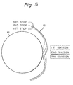
- a prior art divisional dot printing device and the operation thereof are described with reference to Figs. 1 to 7.
- the printing by a printing head 22 mounted on a carriage 21 is applied to a paper 12 on a platen 11.
- the head pins (dot wires) 221-1, 221-2, ... 221-24 are arranged in one row in the vertical direction in the printing head as shown in Fig. 2.
- the upper 1/3 head pins 221-1, 221-2, ... 221-8 constitute the first step division of the head pins.
- the middle 1/3 head pins 221-9, 221-10, ... 221-16 constitute the second step division of the head pins.
- the lower 1/3 head pins 221-17, 221-18, ... 221-24 constitute the third step division of the head pins.
- Fig. 3 The pattern of dots printed according to the divisional printing by the device of Fig. 2 is illustrated in Fig. 3.
- dots are printed by the 1st to 8th head pins.
- dots are printed by the 9th to 16th head pins.
- dots are printed by the 17th to 24th head pins.
- dots printed in the divisional step in question are indicated by black circles, while dots printed in the preceding step or steps are indicated by white circles.
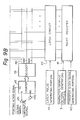
- the device of Fig. 8 includes a platen 11, a paper 12 to be printed, a carriage 21 for a printing head, a printing head 22, a control circuit 3 having a control signal generating portion 4, and a character/graphic pattern generating portion 5.
- the device of Fig. 8 also includes a space controlling portion 61, a carriage driving portion 62, a power source portion 71 having a power source 711 and a capacitor 712, and a voltage detection circuit 72.
- the printing head 22 is provided with a temperature detection element 226.
- the printing operation signal is delivered from a printing operation signal generating portion 225.
- the character/graphic pattern generating portion 5 generates character patterns to be supplied to the control signal generating portion 4 on the basis of the character code supplied to the control circuit 3.
- the structure of the control circuit 3 in the device of Fig. 8 is shown in Fig. 9.
- the control signal generating portion 4 in the control circuit 3 includes a shift register 41, a transfer clock signal generating portion 42, a latch circuit 43, a latch pulse generating portion 44, a counter 45, an OR gate 451, an inverter 452, a decoder 46, AND gates 47-1, 47-2, ... 47-24, transistors 222-1, 222-2, ... 222-24, and pin driving excitation coils 221-1, 221-2, ... 221-24.
- the shift register 41 receives the signal from the character/graphic pattern generating portion 5 and the signal from the transfer clock signal generating portion 42.
- the latch circuit 43 has the same number of steps as the shift register 41.
- the latch circuit 43 receives the signal from the latch pulse generating portion 44.
- the outputs of the latch circuit 43 are supplied to input terminals of the AND gates 47-1, 47-2, ... 47-24.
- the outputs of the decoder 46 are supplied to other input terminals of the AND gates 47-1, 47-2, ... 47-24.
- the output of the AND gate 47-1 is supplied to the base of the transistor 223-1.
- the output of the transistor 222-1 is supplied to the head pin (dot wire) driving excitation coil 221-1.
- the pin driving excitation coil 221-1 drives the head pin 221-1.
- the first output line 461 from the decoder 46 is connected to input terminals of the lst, 4th, 7th, ... and 22nd AND gates; 47-1, 47-4, 47-7, ... 47-22.
- the second output line 462 from the decoder 46 is connected to input terminals of the 2nd, 5th, 8th, ... and the 23rd AND gates; 47-2, 47-5, 47-8, ... 47-23.
- the third output line 463 from the decoder 46 is connected to input terminals of the 3rd, 6th, 9th, ... and 24th AND gates; 47-3, 47-6, 47-9, ... 47-24.
- the decoder 46 receives the signal from the counter 45.
- the output signals of the decoder 46 delivered through the output lines 461, 462, and 463 is regarded as an ENABLE signal.
- An ENABLE signal “1, 1, 1” is delivered when the output of the counter 45 is "0".
- An ENABLE signal "1, 0,0” is delivered when the output of the counter 45 is "1”.
- An ENABLE signal "0, 1, 0” is delivered when the output of the counter 45 is "2”.
- An ENABLE signal "0, 0, 1" is delivered when the output of the counter 45 is "3".
- the output of the counter 45 is "0".
- the counter 45 delivers, outputs "1", "2", and "3" successively.
- a pattern of dots printed according to the distributive printing by the device of Fig. 8 is illustrated in Fig. 10.
- the dots by the lst, 4th, 7th, ... 22nd head pins are printed.
- the dots by the 2nd, 5th, 8th, ... 23rd head pins are printed.
- the dots by the 3rd, 6th, 9th, ... 24th head pins are printed.
- dots printed in the distributive step in question are indicated by black circles, while dots printed in the preceding distributive step or steps, are indicated by white circles.
- the clock input terminal CL of the counter 45 receives the signal of the printing action.
- the gate input terminal G of the counter 45 receives the output of the OR gate 451.
- the reset input terminal RS of the counter 45 receives the output of the inverter 452 which receives the output of the OR gate 451.
- One input terminal of the OR gate 451 receives the voltage detection signal from the voltage detection circuit 72.
- the other input terminal of the OR gate 451 receives the temperature detection signal from the temperature detection element 226.
- the output of the voltage detection circuit 72 and the output of the temperature detection element 226 are also supplied to the space control portion 61.
- the three steps of the distributive printing are carried out as illustrated in Figs llA, 11B, and 11C.
- printing by eight head pins is applied across the same vertical length of the paper 12 at almost the same position. No substantial shift of position of the paper 2 will occur during these three steps.
- gaps and overlapping as shown in Figs 6 and 7 of the prior art are prevented, so that satisfactory printing of a pattern of a broad solid line is achieved.
- the number of steps of the distributive printing can be selected as other than three. However, two or three is considered as the most suitable number of the steps.
- the manner of distribution of head pins in each of the distributive printing steps can be an irregular manner, instead of the above-described manner where one pin out of three is regularly selected.
Landscapes
- Engineering & Computer Science (AREA)
- Multimedia (AREA)
- Signal Processing (AREA)
- Quality & Reliability (AREA)
- Dot-Matrix Printers And Others (AREA)
- Fax Reproducing Arrangements (AREA)
- Impact Printers (AREA)
Applications Claiming Priority (2)
| Application Number | Priority Date | Filing Date | Title |
|---|---|---|---|
| JP276348/84 | 1984-12-28 | ||
| JP59276348A JPH06102382B2 (ja) | 1984-12-28 | 1984-12-28 | プリンタの分割印字装置 |
Publications (3)
| Publication Number | Publication Date |
|---|---|
| EP0186508A2 true EP0186508A2 (de) | 1986-07-02 |
| EP0186508A3 EP0186508A3 (en) | 1987-05-20 |
| EP0186508B1 EP0186508B1 (de) | 1990-08-22 |
Family
ID=17568179
Family Applications (1)
| Application Number | Title | Priority Date | Filing Date |
|---|---|---|---|
| EP85309459A Expired - Lifetime EP0186508B1 (de) | 1984-12-28 | 1985-12-23 | Verteilervorrichtung beim Punktdruck |
Country Status (8)
| Country | Link |
|---|---|
| US (1) | US4743127A (de) |
| EP (1) | EP0186508B1 (de) |
| JP (1) | JPH06102382B2 (de) |
| KR (1) | KR890001391B1 (de) |
| AU (1) | AU562085B2 (de) |
| CA (1) | CA1249171A (de) |
| DE (1) | DE3579305D1 (de) |
| ES (1) | ES8700604A1 (de) |
Cited By (8)
| Publication number | Priority date | Publication date | Assignee | Title |
|---|---|---|---|---|
| EP0262506A1 (de) * | 1986-10-01 | 1988-04-06 | Lexmark International, Inc. | Thermisches Drucken in zwei Durchgängen |
| EP0351798A3 (de) * | 1988-07-21 | 1992-01-08 | Casio Computer Company Limited | Handabtastdrucker |
| US5330276A (en) * | 1989-03-10 | 1994-07-19 | Fujitsu Limited | Divisional step dot printing device |
| EP0620670A1 (de) * | 1993-04-12 | 1994-10-19 | Presstek, Inc. | Verfahren und Vorrichtung zur Korrigierung und Regelung von digitalen Bildausgang |
| US5429441A (en) * | 1991-03-28 | 1995-07-04 | Eastman Kodak Company | Process of printing with serial printhead |
| US5942745A (en) * | 1997-12-17 | 1999-08-24 | Presstek, Inc. | Method and apparatus for digital imaging with reduced periodic artifacts |
| US6087069A (en) * | 1999-04-16 | 2000-07-11 | Presstek, Inc. | Lithographic imaging and cleaning of printing members having boron ceramic layers |
| US6222577B1 (en) | 1999-01-26 | 2001-04-24 | Presstek, Inc. | Multiple-beam, diode-pumped imaging system |
Families Citing this family (8)
| Publication number | Priority date | Publication date | Assignee | Title |
|---|---|---|---|---|
| JP2619521B2 (ja) * | 1989-03-10 | 1997-06-11 | 富士通株式会社 | ドット印刷ヘッドの分割駆動方法 |
| DE69028470T2 (de) * | 1989-10-10 | 1997-02-06 | Tektronix Inc | Verfahren und Gerät zum verschachtelten Druck |
| IT1273141B (it) * | 1994-04-14 | 1997-07-04 | Olivetti Canon Ind Spa | Metodo per migliorare la stampa di immagini grafiche e relativa apparecchiatura di stampa a matrice di punti a getto di inchiostro |
| JP2967052B2 (ja) * | 1995-09-08 | 1999-10-25 | キヤノン株式会社 | カラーフィルタの製造方法及び製造装置 |
| JP3329167B2 (ja) * | 1995-12-20 | 2002-09-30 | セイコーエプソン株式会社 | 印刷装置 |
| US5806421A (en) * | 1995-12-27 | 1998-09-15 | Pitney Bowes Inc. | Method and apparatus for securely printing a machine detectable postal indicia image |
| US5829895A (en) * | 1995-12-27 | 1998-11-03 | Pitney Bowes Inc. | Method for printing an image indicative of value such as a postal indicia |
| US5762428A (en) * | 1995-12-27 | 1998-06-09 | Pitney Bowes Inc. | Method and apparatus for securely printing a postal indicia image by dividing printing of the image in multiple passes |
Family Cites Families (5)
| Publication number | Priority date | Publication date | Assignee | Title |
|---|---|---|---|---|
| DE7115290U (de) * | 1976-06-16 | Nixdorf Computer Ag, 4790 Paderborn | Mosaikdruckkopf | |
| JPS55124684A (en) * | 1979-03-20 | 1980-09-25 | Nippon Telegr & Teleph Corp <Ntt> | Printing velocity controller |
| JPS6027577B2 (ja) * | 1980-03-12 | 1985-06-29 | 株式会社東芝 | 熱記録装置 |
| JPS5784865A (en) * | 1980-11-18 | 1982-05-27 | Oki Electric Ind Co Ltd | Dot line printer |
| JPS5871174A (ja) * | 1981-09-22 | 1983-04-27 | Fujitsu Ltd | 過負荷印字制御方式 |
-
1984
- 1984-12-28 JP JP59276348A patent/JPH06102382B2/ja not_active Expired - Fee Related
-
1985
- 1985-12-23 CA CA000498499A patent/CA1249171A/en not_active Expired
- 1985-12-23 DE DE8585309459T patent/DE3579305D1/de not_active Expired - Lifetime
- 1985-12-23 EP EP85309459A patent/EP0186508B1/de not_active Expired - Lifetime
- 1985-12-24 AU AU51629/85A patent/AU562085B2/en not_active Ceased
- 1985-12-27 ES ES550481A patent/ES8700604A1/es not_active Expired
- 1985-12-27 KR KR1019850009860A patent/KR890001391B1/ko not_active Expired
-
1987
- 1987-08-14 US US07/086,252 patent/US4743127A/en not_active Expired - Lifetime
Cited By (10)
| Publication number | Priority date | Publication date | Assignee | Title |
|---|---|---|---|---|
| EP0262506A1 (de) * | 1986-10-01 | 1988-04-06 | Lexmark International, Inc. | Thermisches Drucken in zwei Durchgängen |
| US4763137A (en) * | 1986-10-01 | 1988-08-09 | International Business Machines Corporation | Two pass thermal printing |
| EP0351798A3 (de) * | 1988-07-21 | 1992-01-08 | Casio Computer Company Limited | Handabtastdrucker |
| US5330276A (en) * | 1989-03-10 | 1994-07-19 | Fujitsu Limited | Divisional step dot printing device |
| US5429441A (en) * | 1991-03-28 | 1995-07-04 | Eastman Kodak Company | Process of printing with serial printhead |
| EP0620670A1 (de) * | 1993-04-12 | 1994-10-19 | Presstek, Inc. | Verfahren und Vorrichtung zur Korrigierung und Regelung von digitalen Bildausgang |
| US5453777A (en) * | 1993-04-12 | 1995-09-26 | Presstek, Inc. | Method and apparatus for correcting and adjusting digital image output |
| US5942745A (en) * | 1997-12-17 | 1999-08-24 | Presstek, Inc. | Method and apparatus for digital imaging with reduced periodic artifacts |
| US6222577B1 (en) | 1999-01-26 | 2001-04-24 | Presstek, Inc. | Multiple-beam, diode-pumped imaging system |
| US6087069A (en) * | 1999-04-16 | 2000-07-11 | Presstek, Inc. | Lithographic imaging and cleaning of printing members having boron ceramic layers |
Also Published As
| Publication number | Publication date |
|---|---|
| JPS61154949A (ja) | 1986-07-14 |
| ES550481A0 (es) | 1986-10-16 |
| AU562085B2 (en) | 1987-05-28 |
| EP0186508B1 (de) | 1990-08-22 |
| KR860004741A (ko) | 1986-07-11 |
| ES8700604A1 (es) | 1986-10-16 |
| CA1249171A (en) | 1989-01-24 |
| US4743127A (en) | 1988-05-10 |
| JPH06102382B2 (ja) | 1994-12-14 |
| AU5162985A (en) | 1986-07-10 |
| DE3579305D1 (de) | 1990-09-27 |
| EP0186508A3 (en) | 1987-05-20 |
| KR890001391B1 (ko) | 1989-05-02 |
Similar Documents
| Publication | Publication Date | Title |
|---|---|---|
| EP0186508B1 (de) | Verteilervorrichtung beim Punktdruck | |
| EP0082978B1 (de) | Schaltkreis zum Steuern eines Vielfachdrathtdruckkopfes | |
| EP0295953A2 (de) | Druckverfahren für thermische Drucker | |
| EP0035746B1 (de) | Aufzeichnungsvorrichtung mit Wärmeeinwirkung | |
| US4560993A (en) | Thermal printing method and thermal printer | |
| US4454516A (en) | Heat-sensitive recording device | |
| US4415904A (en) | Thermal head driving method | |
| EP0478369B1 (de) | Zeilenwärmedrucker | |
| US5729275A (en) | Thermal printhead, drive IC for the same and method for controlling the thermal printhead | |
| EP0079208B1 (de) | Bilddatenaufzeichnungsanlage | |
| EP0223979B1 (de) | Verfahren und Gerät zur Steuerung der Druckqualität eines Thermodruckers | |
| US4186406A (en) | Multiple-electrode print head for electroerosion printers | |
| EP0552719B1 (de) | Treiberkreis für einen Wärmekopf | |
| JPS6440345A (en) | Wire dot printer | |
| US5074684A (en) | Dot printer device having a control unit to print horizontal lines | |
| US5330276A (en) | Divisional step dot printing device | |
| EP0112472B1 (de) | Steuervorrichtung für die Stromversorgung von Druckelementen eines Druckstreifens | |
| JPS599068A (ja) | 感熱印字方式 | |
| EP0373870A2 (de) | Vorrichtung zur Steuerung einer Punktdrucknadel | |
| US4652155A (en) | Printer having a thermal head | |
| CA1089921A (en) | Printer with moving printing head | |
| EP0405825A2 (de) | Thermodrucker | |
| EP0387079B1 (de) | Teilschritt-Punktdrucker | |
| JPS6183079A (ja) | 端末装置 | |
| JPH07304201A (ja) | プリントヘッド駆動ic |
Legal Events
| Date | Code | Title | Description |
|---|---|---|---|
| PUAI | Public reference made under article 153(3) epc to a published international application that has entered the european phase |
Free format text: ORIGINAL CODE: 0009012 |
|
| AK | Designated contracting states |
Kind code of ref document: A2 Designated state(s): DE FR GB IT NL |
|
| PUAL | Search report despatched |
Free format text: ORIGINAL CODE: 0009013 |
|
| AK | Designated contracting states |
Kind code of ref document: A3 Designated state(s): DE FR GB IT NL |
|
| 17P | Request for examination filed |
Effective date: 19871113 |
|
| 17Q | First examination report despatched |
Effective date: 19890419 |
|
| GRAA | (expected) grant |
Free format text: ORIGINAL CODE: 0009210 |
|
| AK | Designated contracting states |
Kind code of ref document: B1 Designated state(s): DE FR GB IT NL |
|
| REF | Corresponds to: |
Ref document number: 3579305 Country of ref document: DE Date of ref document: 19900927 |
|
| ITF | It: translation for a ep patent filed | ||
| ET | Fr: translation filed | ||
| PLBE | No opposition filed within time limit |
Free format text: ORIGINAL CODE: 0009261 |
|
| STAA | Information on the status of an ep patent application or granted ep patent |
Free format text: STATUS: NO OPPOSITION FILED WITHIN TIME LIMIT |
|
| 26N | No opposition filed | ||
| ITTA | It: last paid annual fee | ||
| PGFP | Annual fee paid to national office [announced via postgrant information from national office to epo] |
Ref country code: NL Payment date: 19951230 Year of fee payment: 11 |
|
| PG25 | Lapsed in a contracting state [announced via postgrant information from national office to epo] |
Ref country code: NL Effective date: 19970701 |
|
| NLV4 | Nl: lapsed or anulled due to non-payment of the annual fee |
Effective date: 19970701 |
|
| REG | Reference to a national code |
Ref country code: GB Ref legal event code: IF02 |
|
| PGFP | Annual fee paid to national office [announced via postgrant information from national office to epo] |
Ref country code: FR Payment date: 20031210 Year of fee payment: 19 |
|
| PGFP | Annual fee paid to national office [announced via postgrant information from national office to epo] |
Ref country code: GB Payment date: 20031217 Year of fee payment: 19 |
|
| PGFP | Annual fee paid to national office [announced via postgrant information from national office to epo] |
Ref country code: DE Payment date: 20040102 Year of fee payment: 19 |
|
| PG25 | Lapsed in a contracting state [announced via postgrant information from national office to epo] |
Ref country code: GB Free format text: LAPSE BECAUSE OF NON-PAYMENT OF DUE FEES Effective date: 20041223 |
|
| PG25 | Lapsed in a contracting state [announced via postgrant information from national office to epo] |
Ref country code: DE Free format text: LAPSE BECAUSE OF NON-PAYMENT OF DUE FEES Effective date: 20050701 |
|
| GBPC | Gb: european patent ceased through non-payment of renewal fee |
Effective date: 20041223 |
|
| PG25 | Lapsed in a contracting state [announced via postgrant information from national office to epo] |
Ref country code: FR Free format text: LAPSE BECAUSE OF NON-PAYMENT OF DUE FEES Effective date: 20050831 |
|
| REG | Reference to a national code |
Ref country code: FR Ref legal event code: ST |