EP0186535B1 - Reibungskupplungsgerät mit Nachstellvorrichtung, insbesondere Bremse - Google Patents
Reibungskupplungsgerät mit Nachstellvorrichtung, insbesondere Bremse Download PDFInfo
- Publication number
- EP0186535B1 EP0186535B1 EP85402189A EP85402189A EP0186535B1 EP 0186535 B1 EP0186535 B1 EP 0186535B1 EP 85402189 A EP85402189 A EP 85402189A EP 85402189 A EP85402189 A EP 85402189A EP 0186535 B1 EP0186535 B1 EP 0186535B1
- Authority
- EP
- European Patent Office
- Prior art keywords
- friction
- plunger
- circumferentially
- coupling according
- pusher
- Prior art date
- Legal status (The legal status is an assumption and is not a legal conclusion. Google has not performed a legal analysis and makes no representation as to the accuracy of the status listed.)
- Expired
Links
Images

Classifications
-
- F—MECHANICAL ENGINEERING; LIGHTING; HEATING; WEAPONS; BLASTING
- F16—ENGINEERING ELEMENTS AND UNITS; GENERAL MEASURES FOR PRODUCING AND MAINTAINING EFFECTIVE FUNCTIONING OF MACHINES OR INSTALLATIONS; THERMAL INSULATION IN GENERAL
- F16D—COUPLINGS FOR TRANSMITTING ROTATION; CLUTCHES; BRAKES
- F16D55/00—Brakes with substantially-radial braking surfaces pressed together in axial direction, e.g. disc brakes
- F16D55/02—Brakes with substantially-radial braking surfaces pressed together in axial direction, e.g. disc brakes with axially-movable discs or pads pressed against axially-located rotating members
- F16D55/22—Brakes with substantially-radial braking surfaces pressed together in axial direction, e.g. disc brakes with axially-movable discs or pads pressed against axially-located rotating members by clamping an axially-located rotating disc between movable braking members, e.g. movable brake discs or brake pads
- F16D55/224—Brakes with substantially-radial braking surfaces pressed together in axial direction, e.g. disc brakes with axially-movable discs or pads pressed against axially-located rotating members by clamping an axially-located rotating disc between movable braking members, e.g. movable brake discs or brake pads with a common actuating member for the braking members
- F16D55/2245—Brakes with substantially-radial braking surfaces pressed together in axial direction, e.g. disc brakes with axially-movable discs or pads pressed against axially-located rotating members by clamping an axially-located rotating disc between movable braking members, e.g. movable brake discs or brake pads with a common actuating member for the braking members in which the common actuating member acts on two levers carrying the braking members, e.g. tong-type brakes
-
- F—MECHANICAL ENGINEERING; LIGHTING; HEATING; WEAPONS; BLASTING
- F16—ENGINEERING ELEMENTS AND UNITS; GENERAL MEASURES FOR PRODUCING AND MAINTAINING EFFECTIVE FUNCTIONING OF MACHINES OR INSTALLATIONS; THERMAL INSULATION IN GENERAL
- F16D—COUPLINGS FOR TRANSMITTING ROTATION; CLUTCHES; BRAKES
- F16D65/00—Parts or details
- F16D65/38—Slack adjusters
- F16D65/40—Slack adjusters mechanical
- F16D65/52—Slack adjusters mechanical self-acting in one direction for adjusting excessive play
- F16D65/56—Slack adjusters mechanical self-acting in one direction for adjusting excessive play with screw-thread and nut
- F16D65/567—Slack adjusters mechanical self-acting in one direction for adjusting excessive play with screw-thread and nut for mounting on a disc brake
-
- F—MECHANICAL ENGINEERING; LIGHTING; HEATING; WEAPONS; BLASTING
- F16—ENGINEERING ELEMENTS AND UNITS; GENERAL MEASURES FOR PRODUCING AND MAINTAINING EFFECTIVE FUNCTIONING OF MACHINES OR INSTALLATIONS; THERMAL INSULATION IN GENERAL
- F16D—COUPLINGS FOR TRANSMITTING ROTATION; CLUTCHES; BRAKES
- F16D2121/00—Type of actuator operation force
- F16D2121/14—Mechanical
-
- F—MECHANICAL ENGINEERING; LIGHTING; HEATING; WEAPONS; BLASTING
- F16—ENGINEERING ELEMENTS AND UNITS; GENERAL MEASURES FOR PRODUCING AND MAINTAINING EFFECTIVE FUNCTIONING OF MACHINES OR INSTALLATIONS; THERMAL INSULATION IN GENERAL
- F16D—COUPLINGS FOR TRANSMITTING ROTATION; CLUTCHES; BRAKES
- F16D2125/00—Components of actuators
- F16D2125/18—Mechanical mechanisms
- F16D2125/20—Mechanical mechanisms converting rotation to linear movement or vice versa
- F16D2125/22—Mechanical mechanisms converting rotation to linear movement or vice versa acting transversely to the axis of rotation
- F16D2125/28—Cams; Levers with cams
- F16D2125/32—Cams; Levers with cams acting on one cam follower
Definitions
- the present invention relates to a friction coupling device with wear take-up, such as a brake in particular, comprising friction means and wear take-up means of the latter.
- the invention relates more precisely to the structure of these wear take-up means.
- Such a coupling device intended to frictionally couple a support to which it is linked to an external part animated by a relative movement relative to this support, comprises, for applying its friction means against said external part, an element of clamping coupled to a pusher adapted to move forwards or backwards under the action of a control element.
- the principle of wear compensation consists in maintaining the return travel of this tightening element at a substantially constant value while progressively bringing this tightening element closer to the external part as the wear progressively takes place.
- friction means In practice, the friction means are distributed on either side of this external part so as to pinch the latter.
- the invention applies in particular but not exclusively, in the case of disc brakes for which the safety instructions are very strict in the measure where, even when these brakes are intended to serve as park brakes (or parking brakes) they must also be able to act as a safety brake.
- This requires providing for automatic catching up of the wear of the friction linings of these brakes, unlike the case of drum brakes whose jaws do not wear out as quickly.
- Wear-taking friction friction devices are generally of complex and delicate construction.
- the Applicant has proposed a simple, convenient and reliable coupling device which comprises an expandable pusher whose expansion is controlled by a ratchet wheel whose pawl is coupled to the control element; this wheel acts on the expandable pusher by means of a transmission member which is linked, by three sliding connections under calibrated clamping, respectively, to the ratchet wheel, to the pawl, and to a part of the pusher that this transmission member remains stationary relative to said pusher part when the pawl moves without the ratchet wheel but is driven when the pawl and the ratchet wheel move together.
- This transmission member is in practice a shaft, arranged transversely with respect to the pusher, which controls the unscrewing, within this pusher, of a screw fixed axially with respect to a nut locked in rotation; the sliding connections under calibrated clamping are subjected to an elastic taring member with axial action, parallel to the drive shaft; and the value of the return travel of the clamping element, mounted at the front of the pusher, oscillates between two values whose deviation is defined by the length of the teeth of the ratchet wheel.
- the wear compensation is therefore discontinuous.
- the European patent application No. 0039479 describes a system for taking up wear in a brake in which the control of expansion of the pusher is transmitted by two springs mounted coaxially with said pusher.
- the arrangement is such that the two springs operate at the same time, with the aim of limiting the torque, so that the possible wear compensation is made at the start of the braking stroke.
- the subject of the present invention is a wear take-up friction coupling device which, while being simple, convenient and reliable, is adapted, with as few elements as possible, to ensure wear take-up. continuous and during the return from the braking stroke.
- the invention provides for this purpose a friction coupling device with wear compensation, such as for example a brake intended to frictionally couple a caliper to which it is linked to an external part such as for example a disc, comprising friction means adapted to bear at will against said external part and a device for compensating for the wear of these friction means, adapted to maintain at a substantially constant value the return travel of a clamping element linked to a pusher expandable actuated by a control element, this expandable pusher being adapted, in the event of wear of said friction means to be extended under the control of a rotary member housed in said pusher and coupled by gear to an element thereof ci, this rotary member being also coupled by a mechanism to said control element, characterized in that this mechanism comprises two circumferential friction elements with opposite unidirectional effects, one of which li é to the pusher is mounted on said rotary member in a position tending to block it in rotation relative to the pusher during a forward movement of the latter and the other of which linked to said control element is mounted
- the aforementioned mechanism may include a flexible element and / or a functional clearance in its connection with the pusher.
- the invention allows continuous wear compensation; in addition the invention requires the implementation of only two friction connections thanks to the unidirectional circumferential effects thereof; it will be noted that the friction action of these means results from a phenomenon of radial tightening.
- the invention recommends that the circumferential friction means with a unidirectional effect each consist of at least 2/3 of a turn of a spring which surrounds the rotary body and ensures its rotation, if necessary, by "throttling" it.
- these circumferential friction means can have opposite unidirectional effects while comprising turns wound in the same direction.
- the rotary member comprises a rotary shaft, adapted to control the expansion of the pusher, and a sleeve mounted to slide on this shaft, on which are engaged the circumferential friction means with a unidirectional effect, and which is coupled in rotation to this rotary shaft by a circumferential friction means with unidirectional effect, linked to the bush and engaged on said shaft, adapted to transmit to this shaft only torques tending to make it rotate in said predetermined direction of rotation ( and reciprocally).
- the circumferential friction means advantageously comprises, as previously, at least 2/3 of the turn of a spring adapted to surround the rotary shaft.
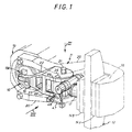
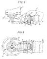
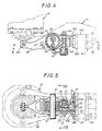
- the embodiment shown in Figures 1 to 7 relates, by way of non-limiting example, an application of the invention to a disc brake for parking braking, in particular for a motor vehicle.
- the mechanical brake control chain includes a wear take-up device.
- This disc brake comprises a friction coupling device 10 comprising a support constituted by a caliper 11, and a disc 12 intended to be coupled to said caliper, at will, under the action of a control device 13 such as a hydraulic cylinder for example controlled itself by a hand brake lever accessible to the driver of the vehicle.
- a control device 13 such as a hydraulic cylinder for example controlled itself by a hand brake lever accessible to the driver of the vehicle.
- the coupling device 10 here has the function of coupling the disc to the stirrup 11, that is to say of immobilizing it.
- the friction coupling device 10 comprises friction means 14A and 14B constituted by brake pads, adapted to be pressed on either side of the disc 12 on friction tracks formed on the latter.
- This coupling device mainly comprises a caliper 11, a lever 16 forming a control element, and a pusher 17.
- the caliper 11 has a bearing surface 10 adapted to receive one, 14A, of the brake pads, by means of screws 19 for example (see Figures 4 and 5), and two arms 20, arranged on either side of the lever 16 and the pusher 17, connected by a pin 21.
- the control lever 16 comprises two branches 22 connected by a veil transverse 23; these branches have two respectively parallel portions, crossed in the vicinity of their free ends by the pin 21, and two respectively converging portions meeting at a common end coupled to a deployable part 13A of the control device 13.
- the pusher 17 is engaged on the pin 21 in a manner which will be detailed later, and carries at its end the plate 14B arranged opposite the plate 14A.
- These plates have in practice a friction lining 24 intended to cooperate with the disc 12 which is attached, for example by bonding to a support plate 25 adapted to be removably fixed either to the stirrup 11 or to the flange 31 of the pusher 17.
- control device 13 the caliper 11, the disc 12 and the brake pads 14A and 14B have been shown so schematic, in dashed lines, in FIG. 1, so as to make the lever 16 and the pusher 17 appear better.
- the mode of articulation of the pusher 17 on the pin 21 and on the lever 16 is particularly apparent from Figures 1, 4 and 5.
- the lever 16 comprises an annex pin 26 on which is engaged, as on the pin 21, a core cylindrical 27 whose axis, oriented perpendicular to the pusher 17, is disposed between these pins.
- This core 27 is slidably engaged in a recess 28 of the pusher.
- the deployable part 13A of the control device is pushed down, it controls the pivoting of the lever 16 around the pin 21.
- This lever causes, by means of the annex pin 26, a rotation eccentric of the core 27 around this pin 21 which induces a displacement to the right of the axis of this core: this results in a translation to the right of the pusher 17.
- the pusher mainly comprises three parts: a pusher body 29 in which is formed the recess 28 in which is disposed the core 27, a cylinder 30, and a flange 31 to which is fixed the brake pad 14B.
- the cylinder 30 is axially coupled, although free in rotation, to the pusher body 29, for example by a screw 32 engaged by its end in the pusher body, surrounded by a tubular guide sleeve and by elastic clamping means 33 now axially the bottom of the hollow cylinder 30 against the pusher body 29.
- This cylinder is externally threaded near its free end 30A forming a screw, and is engaged in a sleeve 31A internally threaded integral with the flange 31 and forming a nut.
- This generally rectangular flange is axially free, although locked in rotation by the cooperation of one of its edges 31 A against a bearing and guiding surface 11A formed on the stirrup 11.
- the rotation of the cylinder 30 is controlled by wear take-up means defined below so as to move, on average, the flange 31 towards the bearing surface 18 of the caliper, as the linings 24 of the pads wear out (and to a lesser extent the friction tracks of the disc 12) so that this flange, which controls the tightening of the friction means, retains, between a tightening configuration and an inactive configuration, a substantially constant round trip.
- the rotation of the cylinder 30 is caused by an endless screw 34 kept substantially fixed axially in a housing 35 (FIGS. 6, 7) formed transversely in the body of the pusher 29 having over a part of its height a thread 36 adapted to cooperate with grooves 37 formed on the outer face of the cylinder 30 axially opposite its thread 30A.
- the worm screw 34 as shown in FIGS. 6 and 7 mainly comprises a hexagonal head 38, an axial support flange 39 intended to cooperate with the body of the pusher, the threaded section 36 above-mentioned, and a portion cylindrical 40 crossed at its end by a diametrical bore intended to receive a transverse blocking rod 41.
- the cylindrical portion 40 is adapted to be slidably engaged in a socket 42 having a body 42A bordered by a transverse flange 42B, it even extended by a tubular portion 42C intended to provide an annular volume around the cylindrical portion 40 of the worm screw 34.
- the housing 35 formed in the pusher body has an enlarged part for receiving the socket, delimited by a transverse bearing 43 intended to serve as a support for the wafer to the tubular portion 42C.
- an elastic element of axial compression 44 such as a Belleville washer, is advantageously disposed between the edge of the body 42A of the sleeve and the transverse rod of locking 41 so as to allow the endless screw a slight axial clearance and to absorb the axial tolerances of the parts.
- first 45 of these elements comprises at least 2/3 of a spring turn which encircles the body of the sleeve 42.
- This element comprises a portion 45A which moves away from the endless screw 34 in a direction substantially parallel to the pin 21 and which ends with a ball 45B engaged in a cavity formed in a block 47A carried by a link 47 carrying at its other end a block 47B in a cavity of which is mounted a ball 48A carried by a link 48 anchored by its other end in one of the arms 22 of the control lever 16.
- the link 47 is substantially oriented parallel to the axis of the pusher and the link 48 is substantially oriented at right angles to the link 47 and to the part 45A of the circumferential friction element 45.
- the second 46 of the circumferential friction elements likewise comprises at least 2/3 of a spring turn engaged on the body 42A of the sleeve. It has one end 46A which moves away from said body 42A and which is adapted to engage in a notch 35A formed axially at the entrance to the enlarged part of the housing 35, for receiving the socket 42 and the worm screw 34. As shown, the turns of the circumferential friction elements 45 and 46 are wound in the same direction.
- the circumferential friction elements 45 and 46 are protected by an elastic cap 49 which is mounted on the bearing surface 35 of the pusher 29 and which is clamped on a housing 45C of the element 45 (see FIG. 6).
- another circumferential friction element 51 is engaged on the endless screw 34 while being linked to the sleeve.
- This element preferably comprises at least 2/3 of a spring turn surrounding the screw 34, one end 51 A of which is engaged in a notch 42D formed axially in the tubular portion 42C of the sleeve. As shown, this turn is wound in a direction opposite to that of the turns of elements 45 and 46.
- This element 51 has the function of preventing the worm from undergoing excessive drive torques from the sleeve; it also has the role of allowing the rotation of the endless screw 34 during manual adjustments of its angular position, in particular after replacing the brake pads 14A and 14B, by action on its hexagonal head 38.
- the pivoting of the control lever causes, in addition to a bending of the part 45A of the element 45, an unwinding of the spring coil associated (due to its winding direction), which causes an angular sliding of this turn vis-à-vis this socket. Due to its winding direction, the spring coil of the element 46 tends to "throttle" the sleeve and prevents any rotation under the effect of the element 45. During the subsequent phase of brake release, the element 45 tends to throttle the sleeve and to make it rotate (clockwise in FIG. 7), to which element 46 does not tend to oppose because this rotation tends to widen its spring turn.
- the torque applied by the element 45 is greater than the sum of the torque applied by the element 46 when it releases its constriction and the various frictions of the mechanical effects transmission chain.
- the elastic element of axial compression 44 then has the advantage of allowing the screw 34 to rotate under the action of the element 51 by describing a helical movement.
- the compression of the elastic element 44 then ensures a sort of storage of the rotation which should be applied to the cylinder 30 as soon as this becomes possible, during one or more phases of application of the brake. .
- the rotary member constituted by the worm and the socket can alternatively be replaced by a single piece, or the connection between the socket and the worm can be modified in its structure.
- the number of turns of elements 45 and 46 can be modified, and they can likewise lend themselves to numerous structural variants; as a variant, for example, they can be engaged in a tubular part of the socket; in another variant, friction can occur between the elements 45 and 46 and the control element and the pusher, respectively.
- the direction of winding of the turns, when these elements 45 and 46 comprise it can vary from one element to another (depending for example on the arm 22 to which the link 48 is attached).
- the clamping element of the friction means is not always carried by the front end of the pusher, a more complex mechanical connection may be preferred in certain cases.
Landscapes
- Engineering & Computer Science (AREA)
- General Engineering & Computer Science (AREA)
- Mechanical Engineering (AREA)
- Braking Arrangements (AREA)
Claims (9)
Applications Claiming Priority (2)
| Application Number | Priority Date | Filing Date | Title |
|---|---|---|---|
| FR8417302A FR2573154B1 (fr) | 1984-11-13 | 1984-11-13 | Appareil d'accouplement par friction a rattrapage d'usure, tel que frein notamment |
| FR8417302 | 1984-11-13 |
Publications (2)
| Publication Number | Publication Date |
|---|---|
| EP0186535A1 EP0186535A1 (de) | 1986-07-02 |
| EP0186535B1 true EP0186535B1 (de) | 1988-06-08 |
Family
ID=9309549
Family Applications (1)
| Application Number | Title | Priority Date | Filing Date |
|---|---|---|---|
| EP85402189A Expired EP0186535B1 (de) | 1984-11-13 | 1985-11-13 | Reibungskupplungsgerät mit Nachstellvorrichtung, insbesondere Bremse |
Country Status (4)
| Country | Link |
|---|---|
| US (1) | US4727963A (de) |
| EP (1) | EP0186535B1 (de) |
| DE (1) | DE3563249D1 (de) |
| FR (1) | FR2573154B1 (de) |
Families Citing this family (6)
| Publication number | Priority date | Publication date | Assignee | Title |
|---|---|---|---|---|
| EP0639246B1 (de) * | 1992-05-05 | 1996-01-17 | Lucas Industries Public Limited Company | Betätigungsvorrichtung mit selbsttätiger nachstellung an scheibenbremsen, insbesondere für lastkraftwagen und omnibusse |
| FR2706004B1 (fr) * | 1993-06-02 | 1995-10-13 | Alliedsignal Europ Services | Frein à disque utilisable sur les véhicules industriels. |
| US5718308A (en) * | 1996-02-02 | 1998-02-17 | Chung; Chiang-Hai | Automatic brake-adjusting device |
| DE10125552C2 (de) * | 2001-05-23 | 2003-05-28 | Messer Griesheim Gmbh | Lötvorrichtung zum Löten von Flachbaugruppen |
| EP3184386B2 (de) * | 2015-12-22 | 2024-04-10 | Haldex Brake Products AB | Bremsscheibe und verfahren zur herstellung davon |
| CN109563896A (zh) * | 2017-05-31 | 2019-04-02 | 马德拉斯工程工业私人有限公司 | 自动间隙调整器 |
Family Cites Families (19)
| Publication number | Priority date | Publication date | Assignee | Title |
|---|---|---|---|---|
| US1283634A (en) * | 1914-12-28 | 1918-11-05 | Knut Anton Beckman | Automatic slack-adjuster for railway-brakes. |
| US3115217A (en) * | 1960-06-02 | 1963-12-24 | Dunlop Rubber Co | Cam-ball actuated spot brake with slack adjusting means |
| GB1118625A (en) * | 1964-08-29 | 1968-07-03 | Girling Ltd | Applying mechanism for brakes |
| DE1600210A1 (de) * | 1966-08-03 | 1972-02-10 | Westinghouse Bremsen Apparate | Selbsttaetige Nachstellvorrichtung fuer den Bremshebel der Bremsnockenwelle einer Bremse |
| DE1916858A1 (de) * | 1969-04-02 | 1970-10-15 | Bosch Gmbh Robert | Selbsttaetige Nachstellvorrichtung |
| US3848705A (en) * | 1973-08-13 | 1974-11-19 | Bendix Corp | Application adjuster for disc brake |
| US3921765A (en) * | 1974-02-19 | 1975-11-25 | Aeroquip Corp | Automatic brake slack adjuster |
| US3901357A (en) * | 1974-07-01 | 1975-08-26 | Bendix Corp | Automatic slack adjuster |
| FR2315636A1 (fr) * | 1975-06-23 | 1977-01-21 | Dba | Frein a tambour |
| NL7606149A (nl) * | 1975-06-23 | 1976-12-27 | Dba Sa | Instelinrichting voor een trommelrem. |
| US4015692A (en) * | 1975-11-06 | 1977-04-05 | Borg-Warner Corporation | Automatic slack adjuster |
| US4019612A (en) * | 1976-07-14 | 1977-04-26 | Borg-Warner Corporation | Automatic slack adjuster with internal reference point |
| US4399894A (en) * | 1979-02-14 | 1983-08-23 | Kelsey-Hayes Company | Push rod slack adjuster |
| US4351419A (en) * | 1980-05-07 | 1982-09-28 | Eaton Corporation | Automatic slack adjuster |
| US4384638A (en) * | 1981-01-12 | 1983-05-24 | Aeroquip Corporation | Automatic brake slack adjuster |
| FR2504076B1 (fr) * | 1981-04-17 | 1985-06-14 | Valeo | Commande mecanique de frein se composant d'un excentrique |
| US4454933A (en) * | 1981-04-27 | 1984-06-19 | Kelsey Hayes Company | Disc brake |
| US4478317A (en) * | 1983-04-11 | 1984-10-23 | Rockwell International Corporation | Slack adjuster for a disc brake |
| FR2548310B1 (fr) * | 1983-06-30 | 1985-12-13 | Valeo | Appareil d'accouplement tel que frein ou analogue avec un rattrapeur d'usure |
-
1984
- 1984-11-13 FR FR8417302A patent/FR2573154B1/fr not_active Expired - Lifetime
-
1985
- 1985-11-12 US US06/796,994 patent/US4727963A/en not_active Expired - Lifetime
- 1985-11-13 DE DE8585402189T patent/DE3563249D1/de not_active Expired
- 1985-11-13 EP EP85402189A patent/EP0186535B1/de not_active Expired
Also Published As
| Publication number | Publication date |
|---|---|
| FR2573154A1 (fr) | 1986-05-16 |
| FR2573154B1 (fr) | 1990-06-15 |
| DE3563249D1 (en) | 1988-07-14 |
| US4727963A (en) | 1988-03-01 |
| EP0186535A1 (de) | 1986-07-02 |
Similar Documents
| Publication | Publication Date | Title |
|---|---|---|
| EP3090190B1 (de) | Aktuator mit irreversiblem gewinde, trommelbremsaktuator und bremsvorrichtung mit so einem aktuator | |
| FR2493942A1 (fr) | Dispositif automatique de reglage equipant un mecanisme d'actionnement et son cable de commande | |
| FR2934228A1 (fr) | Dispositif de poussoir a exentrique pour direction a cremaillere de vehicule automobile | |
| FR2630794A1 (fr) | Frein a disque a etrier coulissant a commande mecanique | |
| EP0734496B1 (de) | Automatisch nachstellbare strebe für eine trommelbremse | |
| EP0186535A1 (de) | Reibungskupplungsgerät mit Nachstellvorrichtung, insbesondere Bremse | |
| EP0186537B1 (de) | Scheibenbremse | |
| EP0125959B1 (de) | Bremsvorrichtung mit mechanischem Antrieb | |
| FR2509404A1 (fr) | Frein a tambour a rattrapage automatique d'usure | |
| CA2679688C (fr) | Actionneur telescopique a tige principale et tige auxiliaire | |
| FR2537230A2 (fr) | Dispositif de reglage automatique pour frein | |
| FR3121409A1 (fr) | Dispositif d’immobilisation en stationnement pour véhicule électrique | |
| EP0531178B1 (de) | Selbsttätige Nachstellvorrichtung für einen Bremsmechanismus | |
| CA2591973A1 (fr) | Cle a cliquet | |
| EP1343977B1 (de) | Scheibenbremszylinder mit einem feststellbremsmechanismus | |
| FR2514847A1 (fr) | Frein a tambour et entretoise pour un tel frein | |
| FR2493441A1 (fr) | Frein a disque a selle coulissante a commande mecanique | |
| FR2761654A1 (fr) | Dispositif de commande a lien souple et a rattrapage de jeu | |
| FR2849136A1 (fr) | Moteur de frein a disque a rattrapage d'usure, et frein a disque equipe d'un tel moteur | |
| FR2564395A1 (fr) | Enrouleur de ceinture de securite | |
| EP0367643B1 (de) | Automatisch nachstellbare Strebe für eine Trommelbremse | |
| EP0907035A1 (de) | Strebe mit automatischer Verschleissnachstellung für eine Trommelbremse sowie mit einer solchen Strebe ausgerüstete Trommelbremse | |
| EP0003452B1 (de) | Trommelbremse | |
| FR2509405A1 (fr) | Frein a tambour a reglage automatique | |
| EP0642634B1 (de) | Trommelbremse mit hilfseinrichtung zum automatischen nachstellen |
Legal Events
| Date | Code | Title | Description |
|---|---|---|---|
| PUAI | Public reference made under article 153(3) epc to a published international application that has entered the european phase |
Free format text: ORIGINAL CODE: 0009012 |
|
| AK | Designated contracting states |
Kind code of ref document: A1 Designated state(s): DE GB IT |
|
| 17P | Request for examination filed |
Effective date: 19860814 |
|
| 17Q | First examination report despatched |
Effective date: 19870916 |
|
| GRAA | (expected) grant |
Free format text: ORIGINAL CODE: 0009210 |
|
| AK | Designated contracting states |
Kind code of ref document: B1 Designated state(s): DE GB IT |
|
| GBT | Gb: translation of ep patent filed (gb section 77(6)(a)/1977) | ||
| REF | Corresponds to: |
Ref document number: 3563249 Country of ref document: DE Date of ref document: 19880714 |
|
| ITF | It: translation for a ep patent filed | ||
| PLBE | No opposition filed within time limit |
Free format text: ORIGINAL CODE: 0009261 |
|
| STAA | Information on the status of an ep patent application or granted ep patent |
Free format text: STATUS: NO OPPOSITION FILED WITHIN TIME LIMIT |
|
| 26N | No opposition filed | ||
| ITTA | It: last paid annual fee | ||
| ITPR | It: changes in ownership of a european patent |
Owner name: CAMBIO SEDE;BREMBO KELSEY HAYES S.P.A. |
|
| REG | Reference to a national code |
Ref country code: GB Ref legal event code: 732E |
|
| PGFP | Annual fee paid to national office [announced via postgrant information from national office to epo] |
Ref country code: GB Payment date: 19971218 Year of fee payment: 13 |
|
| PGFP | Annual fee paid to national office [announced via postgrant information from national office to epo] |
Ref country code: DE Payment date: 19971222 Year of fee payment: 13 |
|
| PG25 | Lapsed in a contracting state [announced via postgrant information from national office to epo] |
Ref country code: GB Free format text: LAPSE BECAUSE OF NON-PAYMENT OF DUE FEES Effective date: 19981113 |
|
| GBPC | Gb: european patent ceased through non-payment of renewal fee |
Effective date: 19981113 |
|
| PG25 | Lapsed in a contracting state [announced via postgrant information from national office to epo] |
Ref country code: DE Free format text: LAPSE BECAUSE OF NON-PAYMENT OF DUE FEES Effective date: 19990901 |