EP0186539A1 - Lötmaschine - Google Patents
Lötmaschine Download PDFInfo
- Publication number
- EP0186539A1 EP0186539A1 EP85402213A EP85402213A EP0186539A1 EP 0186539 A1 EP0186539 A1 EP 0186539A1 EP 85402213 A EP85402213 A EP 85402213A EP 85402213 A EP85402213 A EP 85402213A EP 0186539 A1 EP0186539 A1 EP 0186539A1
- Authority
- EP
- European Patent Office
- Prior art keywords
- machine
- wall
- machine according
- median plane
- closed position
- Prior art date
- Legal status (The legal status is an assumption and is not a legal conclusion. Google has not performed a legal analysis and makes no representation as to the accuracy of the status listed.)
- Granted
Links
Images


Classifications
-
- B—PERFORMING OPERATIONS; TRANSPORTING
- B23—MACHINE TOOLS; METAL-WORKING NOT OTHERWISE PROVIDED FOR
- B23K—SOLDERING OR UNSOLDERING; WELDING; CLADDING OR PLATING BY SOLDERING OR WELDING; CUTTING BY APPLYING HEAT LOCALLY, e.g. FLAME CUTTING; WORKING BY LASER BEAM
- B23K3/00—Tools, devices or special appurtenances for soldering, e.g. brazing, or unsoldering, not specially adapted for particular methods
- B23K3/06—Solder feeding devices; Solder melting pans
- B23K3/0646—Solder baths
- B23K3/0669—Solder baths with dipping means
- B23K3/0676—Conveyors therefor
-
- B—PERFORMING OPERATIONS; TRANSPORTING
- B23—MACHINE TOOLS; METAL-WORKING NOT OTHERWISE PROVIDED FOR
- B23K—SOLDERING OR UNSOLDERING; WELDING; CLADDING OR PLATING BY SOLDERING OR WELDING; CUTTING BY APPLYING HEAT LOCALLY, e.g. FLAME CUTTING; WORKING BY LASER BEAM
- B23K3/00—Tools, devices or special appurtenances for soldering, e.g. brazing, or unsoldering, not specially adapted for particular methods
- B23K3/06—Solder feeding devices; Solder melting pans
- B23K3/0646—Solder baths
- B23K3/0653—Solder baths with wave generating means, e.g. nozzles, jets, fountains
Definitions
- the present invention relates to a wave welding machine.
- These machines typically comprise an elongated frame on which are successively arranged a fluxing device, a preheating device then a welding pot, as well as a substantially horizontal conveyor or in slight upward or downward slope above these elements, intended to drive printed circuit boards along an appropriate path with respect to the fluxing device, the preheating apparatus and the welding pot in particular.
- a cover covers the assembly both to prevent the ingress of dust from the outside which would adversely affect the good quality of the welds, to also avoid uncontrolled movements of the air masses, and to prevent the fumes which occur in the machine will not spread outside.
- This cowling is provided with panes allowing the visual control of the operations taking place in the machine, as well as doors giving access to the various elements for the necessary interventions, in particular the cleaning of the machine.
- the problem which the invention aims to solve is to design a welding machine, as set out above, so as to have excellent accessibility, both visual and physical, allowing good functional control, a reduction in the duration of maintenance or cleaning, adjustment, repair, etc.
- the present invention provides a wave soldering machine for printed circuit boards, comprising an elongated frame resting on the ground and defining at its upper part an installation plane on which the constituent elements of the machine, namely: a fluxing device, a preheating device and a welding, as well as a conveyor extending above the aforementioned devices substantially horizontally or in a slightly upward or downward slope and intended to drive printed circuit boards along an appropriate path with respect to the devices of the machine; said component elements having a longitudinal vertical median plane, said machine comprising a covering covering said elements and provided with visual inspection windows and access doors, characterized in that said covering comprises on one side of said median plane and substantially on the entire length of the machine a front wall, glazed over most of its surface, inclined in the closed position, from a substantially horizontal upper edge situated above the constituent elements and in the vicinity of their median plane, up to an edge substantially horizontal lower located cantilevered outside the constituent elements and at a short distance, in the vertical direction, from said installation plane, said front wall being rotatably mounted around
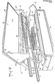
- the welding machine according to the invention is illustrated in perspective in Figure 1 in its normal operating condition called “closed”, and in Figure 2 in an "open” condition where its cover is released to allow access to its interior elements.
- a conveyor 20 intended to drive printed circuit boards (not shown) along a rectilinear, horizontal or even slightly upward or downward slope, so that the boards laid out flat are presented. successively opposite the fluxing device where their lower faces are licking a wave of fluxing product, then facing the preheating device where they are brought to a predetermined temperature, and finally facing the welding pot where their lower faces are licking a wave of molten solder alloy produced by an upper nozzle.
- the fixed wall known as the rear wall with respect to the side from which the machine is accessed, has a vertical section (28) from the rear edge 30 of the installation plane, followed by a section 32 inclined at 45 ending in a upper edge 33 substantially horizontal and located in the median plane P, or a short distance from it.
- the removable walls 26 comprise a front glazed wall 34 and a folding flap 36.
- the glazed wall 34 extends, in the closed position illustrated in FIG. 1, from the upper edge 33, to a lower edge 38, also horizontal and located cantilevered outside the machine and at a short distance, vertically, above the installation plan.
- the glazed wall is flat and inclined also at 45 ° and it is glazed over most of its surface, the glazing 40 being produced by a sheet of glass or transparent plastic material surrounded by a frame 42.
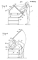
- the particular arrangement of the glazed wall 34 allows excellent visual inspection of the interior of the machine, both by short people (figure A) and by tall people (figure B) . All parts of the machine are accessible to the eye, both the parts close to the top and the parts close to the installation plan from its rear edge to its front edge, and this without any significant change in posture, particularly of the head.
- the glazed wall extends in the open position substantially in alignment with the inclined section of the fixed rear wall and its lower edge is then at a distance above the ground accessible by extension of the arm.
- the entire interior volume of the machine is therefore accessible both by short people (figure A) and by tall people (figure B), the working position being particularly favorable from an ergonomic point of view.
- the machine also includes a mobile control console 46, composed of a switchgear box 48 and a connecting bracket 50, mounted on the frame by means of a carriage 52. As illustrated in FIG. 5, the carriage 52 has bearings 53 cooperating with a rail 54 secured to the frame over the entire length thereof.
- the console provides positive safety against accidental opening of the machine.
- the picture box is oriented parallel to the glass wall and at a short distance from it in the vicinity of its lower edge, which physically prevents its opening;
- the bracket 50 is oriented parallel to the folding shutter and at a short distance from the latter, which also prevents its opening.
- an electro-mechanical safety device will also be provided preventing the carriage from returning, or at least the neutralization of the console keyboard, since disassembly of the folding flap would allow the console to return to a working position.
- this electro-mechanical safety - or this neutralization of the console keyboard - can be canceled by means of a device to key, or by dialing a code on the keyboard.
- the same inclined section of the rear wall is also provided with an air suction device 58, intended to evacuate the fumes and fumes which occur inside the machine.
- the air intake takes place on the one hand via the openings corresponding to the conveyor at the two ends of the machine, and on the other hand via a lip 60 formed either between the glazed wall and the folding flap, or between the latter. and the installation plan. There are therefore practically no “dead” zones, that is to say zones which are not swept by the air flow passing through the machine.
- the glass wall carries vertical closing cheeks 62 and 64, occupying, in the closed position, all the space separating the glass wall, the fixed rear wall and the upper edge of the conveyor 22 considered in the position of job.
- shutter cheeks therefore ensure the closing of the machine at its ends so that the only free passage for air is represented by the openings corresponding to the conveyor. They also constitute a physical obstacle intended to prevent the raising of the conveyor when the glass wall is in the closed position (FIG. 1).
- These components preferably include the liquid solder alloy circulation pump 68 and the associated members; engine, transmission, regulator, as well as the drain fitting 70.
- the cowling is entirely removable and insofar as it does not carry any of the essential functional elements of the machine, the machine can first of all be assembled and developed without its cowling, therefore accessible on all sides during this phase, the cowling being assembled at the last moment, without requiring additional adjustments to be made due to its assembly.
Landscapes
- Engineering & Computer Science (AREA)
- Mechanical Engineering (AREA)
- Electric Connection Of Electric Components To Printed Circuits (AREA)
- Molten Solder (AREA)
- Casings For Electric Apparatus (AREA)
- Motor Or Generator Frames (AREA)
- Lining Or Joining Of Plastics Or The Like (AREA)
Priority Applications (1)
| Application Number | Priority Date | Filing Date | Title |
|---|---|---|---|
| AT85402213T ATE49915T1 (de) | 1984-11-15 | 1985-11-15 | Loetmaschine. |
Applications Claiming Priority (2)
| Application Number | Priority Date | Filing Date | Title |
|---|---|---|---|
| FR8417452A FR2572977B1 (fr) | 1984-11-15 | 1984-11-15 | Capotage de protection pour machine de soudage a la vague. |
| FR8417452 | 1984-11-15 |
Publications (2)
| Publication Number | Publication Date |
|---|---|
| EP0186539A1 true EP0186539A1 (de) | 1986-07-02 |
| EP0186539B1 EP0186539B1 (de) | 1990-01-31 |
Family
ID=9309632
Family Applications (1)
| Application Number | Title | Priority Date | Filing Date |
|---|---|---|---|
| EP85402213A Expired - Lifetime EP0186539B1 (de) | 1984-11-15 | 1985-11-15 | Lötmaschine |
Country Status (5)
| Country | Link |
|---|---|
| EP (1) | EP0186539B1 (de) |
| JP (1) | JPS61126964A (de) |
| AT (1) | ATE49915T1 (de) |
| DE (1) | DE3575692D1 (de) |
| FR (1) | FR2572977B1 (de) |
Cited By (1)
| Publication number | Priority date | Publication date | Assignee | Title |
|---|---|---|---|---|
| CN101412134B (zh) * | 2008-12-01 | 2010-09-08 | 陈国英 | 分体式波峰焊机 |
Families Citing this family (1)
| Publication number | Priority date | Publication date | Assignee | Title |
|---|---|---|---|---|
| CN112518068B (zh) * | 2020-12-16 | 2023-12-05 | 彼勒豪斯(苏州)自动焊锡系统有限公司 | 一种电子元件选择性波峰焊接设备 |
Citations (1)
| Publication number | Priority date | Publication date | Assignee | Title |
|---|---|---|---|---|
| DE3141825C1 (de) * | 1981-10-19 | 1982-11-04 | ERSA Ernst Sachs GmbH & Co KG, 6980 Wertheim | Lötmaschine |
-
1984
- 1984-11-15 FR FR8417452A patent/FR2572977B1/fr not_active Expired
-
1985
- 1985-11-15 JP JP60256510A patent/JPS61126964A/ja active Pending
- 1985-11-15 DE DE8585402213T patent/DE3575692D1/de not_active Expired - Fee Related
- 1985-11-15 EP EP85402213A patent/EP0186539B1/de not_active Expired - Lifetime
- 1985-11-15 AT AT85402213T patent/ATE49915T1/de not_active IP Right Cessation
Patent Citations (1)
| Publication number | Priority date | Publication date | Assignee | Title |
|---|---|---|---|---|
| DE3141825C1 (de) * | 1981-10-19 | 1982-11-04 | ERSA Ernst Sachs GmbH & Co KG, 6980 Wertheim | Lötmaschine |
Cited By (1)
| Publication number | Priority date | Publication date | Assignee | Title |
|---|---|---|---|---|
| CN101412134B (zh) * | 2008-12-01 | 2010-09-08 | 陈国英 | 分体式波峰焊机 |
Also Published As
| Publication number | Publication date |
|---|---|
| FR2572977B1 (fr) | 1987-02-13 |
| EP0186539B1 (de) | 1990-01-31 |
| JPS61126964A (ja) | 1986-06-14 |
| DE3575692D1 (de) | 1990-03-08 |
| FR2572977A1 (fr) | 1986-05-16 |
| ATE49915T1 (de) | 1990-02-15 |
Similar Documents
| Publication | Publication Date | Title |
|---|---|---|
| EP3309380A1 (de) | Gasturbinentriebwerksgondel umfassend einer schubumkehrklappe | |
| FR2486788A1 (fr) | Siege, en particulier siege de vehicule automobile | |
| FR2587322A1 (fr) | Cabine pour chariot elevateur industriel et chariot elevateur industriel equipe d'une telle cabine. | |
| EP0186539B1 (de) | Lötmaschine | |
| FR2605558A1 (fr) | Porte, ou section de carrosserie, d'un vehicule, notamment une voiture de tourisme | |
| EP0335048A1 (de) | Panorama-Kamintür mit mehreren Seiten | |
| FR2811702A1 (fr) | Module de fenetre auto-nettoyante | |
| FR2720991A1 (fr) | Dispositif d'essuyage de vitres des deux portes battantes arrière d'un véhicule automobile. | |
| FR3040722A1 (fr) | Porte basculante a ouverture verticale motorisee | |
| EP1277607B1 (de) | Fahrerkabine einer Baumaschine mit einer Vorrichtung zum Öffnen und Schliessen einer Tür, und Baumaschine mit einer solchen Fahrerkabine | |
| EP3809544B1 (de) | System zum verriegeln der bewegung einer halterung für elektrische komponenten in einem schaltschrank, insbesondere einem atex-zertifizierten schaltschrank, und schaltschrank, der mit einer solchen halterung ausgestattet ist | |
| FR2595403A1 (fr) | Dispositif de projection d'un volet roulant et volet pourvu de ce dispositif | |
| EP0347270B1 (de) | Vervollkommung an Schleifmaschinen | |
| EP3320778A1 (de) | Ofen, der abdichtungsmittel umfasst | |
| EP0305248A1 (de) | Entlüftungsgerät für Kocheinrichtungen, wie Öfen, Kochmulden oder Kochherde | |
| FR2529250A1 (fr) | Porte basculante motorisee | |
| FR2639992A2 (fr) | Fenetre oscillobattante a trois modes d'ouverture et a deux vantaux | |
| CA1264628A (fr) | Porte escamotable et son mecanisme de commande pour foyer ferme, en particulier foyer ferme de cheminee | |
| FR3102452A1 (fr) | Caisson comprenant une porte de type accordeon a multiples panneaux pour un vehicule automobile | |
| FR2739811A1 (fr) | Vitre de custode susceptible de coulisser longitudinalement | |
| EP0924377A1 (de) | Scharnierbeschlag für Tür, Fenster oder dgl | |
| FR2743180A1 (fr) | Carter pour panneau d'affichage et panneau d'affichage comportant un tel carter | |
| EP0172760B1 (de) | Schiebeabschlusstür an einer Feuerstelle | |
| FR2604776A1 (fr) | Table de cuisson | |
| EP1321718B1 (de) | Vorrichtung zum Freigeben einer Schwenktürverkleidung |
Legal Events
| Date | Code | Title | Description |
|---|---|---|---|
| PUAI | Public reference made under article 153(3) epc to a published international application that has entered the european phase |
Free format text: ORIGINAL CODE: 0009012 |
|
| AK | Designated contracting states |
Kind code of ref document: A1 Designated state(s): AT BE CH DE GB IT LI LU NL SE |
|
| 17P | Request for examination filed |
Effective date: 19861208 |
|
| 17Q | First examination report despatched |
Effective date: 19880704 |
|
| ITF | It: translation for a ep patent filed | ||
| GRAA | (expected) grant |
Free format text: ORIGINAL CODE: 0009210 |
|
| AK | Designated contracting states |
Kind code of ref document: B1 Designated state(s): AT BE CH DE GB IT LI LU NL SE |
|
| REF | Corresponds to: |
Ref document number: 49915 Country of ref document: AT Date of ref document: 19900215 Kind code of ref document: T |
|
| REF | Corresponds to: |
Ref document number: 3575692 Country of ref document: DE Date of ref document: 19900308 |
|
| GBT | Gb: translation of ep patent filed (gb section 77(6)(a)/1977) | ||
| PG25 | Lapsed in a contracting state [announced via postgrant information from national office to epo] |
Ref country code: GB Effective date: 19901115 Ref country code: AT Effective date: 19901115 |
|
| PLBE | No opposition filed within time limit |
Free format text: ORIGINAL CODE: 0009261 |
|
| STAA | Information on the status of an ep patent application or granted ep patent |
Free format text: STATUS: NO OPPOSITION FILED WITHIN TIME LIMIT |
|
| 26N | No opposition filed | ||
| BERE | Be: lapsed |
Owner name: S.A. OSL OUTILLAGES SCIENTIFIQUES ET DE LABORATOI Effective date: 19901130 |
|
| GBPC | Gb: european patent ceased through non-payment of renewal fee | ||
| PGFP | Annual fee paid to national office [announced via postgrant information from national office to epo] |
Ref country code: LU Payment date: 19911118 Year of fee payment: 7 Ref country code: CH Payment date: 19911118 Year of fee payment: 7 |
|
| PGFP | Annual fee paid to national office [announced via postgrant information from national office to epo] |
Ref country code: DE Payment date: 19911122 Year of fee payment: 7 |
|
| PGFP | Annual fee paid to national office [announced via postgrant information from national office to epo] |
Ref country code: SE Payment date: 19911125 Year of fee payment: 7 |
|
| ITTA | It: last paid annual fee | ||
| PGFP | Annual fee paid to national office [announced via postgrant information from national office to epo] |
Ref country code: NL Payment date: 19911130 Year of fee payment: 7 |
|
| PGFP | Annual fee paid to national office [announced via postgrant information from national office to epo] |
Ref country code: BE Payment date: 19911217 Year of fee payment: 7 |
|
| EPTA | Lu: last paid annual fee | ||
| PG25 | Lapsed in a contracting state [announced via postgrant information from national office to epo] |
Ref country code: LU Free format text: LAPSE BECAUSE OF NON-PAYMENT OF DUE FEES Effective date: 19921115 |
|
| PG25 | Lapsed in a contracting state [announced via postgrant information from national office to epo] |
Ref country code: SE Effective date: 19921116 |
|
| PG25 | Lapsed in a contracting state [announced via postgrant information from national office to epo] |
Ref country code: LI Effective date: 19921130 Ref country code: CH Effective date: 19921130 Ref country code: BE Effective date: 19921130 |
|
| BERE | Be: lapsed |
Owner name: S.A. OSL OUTILLAGES SCIENTIFIQUES ET DE LABORATOI Effective date: 19921130 |
|
| PG25 | Lapsed in a contracting state [announced via postgrant information from national office to epo] |
Ref country code: NL Effective date: 19930601 |
|
| NLV4 | Nl: lapsed or anulled due to non-payment of the annual fee | ||
| REG | Reference to a national code |
Ref country code: CH Ref legal event code: PL |
|
| PG25 | Lapsed in a contracting state [announced via postgrant information from national office to epo] |
Ref country code: DE Effective date: 19930803 |
|
| EUG | Se: european patent has lapsed |
Ref document number: 85402213.4 Effective date: 19930610 |