EP0186561B1 - Abfallverbrennungsverfahren mit Temperaturkontrolle - Google Patents
Abfallverbrennungsverfahren mit Temperaturkontrolle Download PDFInfo
- Publication number
- EP0186561B1 EP0186561B1 EP85402380A EP85402380A EP0186561B1 EP 0186561 B1 EP0186561 B1 EP 0186561B1 EP 85402380 A EP85402380 A EP 85402380A EP 85402380 A EP85402380 A EP 85402380A EP 0186561 B1 EP0186561 B1 EP 0186561B1
- Authority
- EP
- European Patent Office
- Prior art keywords
- oxygen
- furnace
- liquid
- temperature
- waste products
- Prior art date
- Legal status (The legal status is an assumption and is not a legal conclusion. Google has not performed a legal analysis and makes no representation as to the accuracy of the status listed.)
- Expired
Links
Images


Classifications
-
- F—MECHANICAL ENGINEERING; LIGHTING; HEATING; WEAPONS; BLASTING
- F23—COMBUSTION APPARATUS; COMBUSTION PROCESSES
- F23L—SUPPLYING AIR OR NON-COMBUSTIBLE LIQUIDS OR GASES TO COMBUSTION APPARATUS IN GENERAL ; VALVES OR DAMPERS SPECIALLY ADAPTED FOR CONTROLLING AIR SUPPLY OR DRAUGHT IN COMBUSTION APPARATUS; INDUCING DRAUGHT IN COMBUSTION APPARATUS; TOPS FOR CHIMNEYS OR VENTILATING SHAFTS; TERMINALS FOR FLUES
- F23L7/00—Supplying non-combustible liquids or gases, other than air, to the fire, e.g. oxygen, steam
-
- F—MECHANICAL ENGINEERING; LIGHTING; HEATING; WEAPONS; BLASTING
- F23—COMBUSTION APPARATUS; COMBUSTION PROCESSES
- F23G—CREMATION FURNACES; CONSUMING WASTE PRODUCTS BY COMBUSTION
- F23G2207/00—Control
- F23G2207/10—Arrangement of sensing devices
- F23G2207/101—Arrangement of sensing devices for temperature
-
- F—MECHANICAL ENGINEERING; LIGHTING; HEATING; WEAPONS; BLASTING
- F23—COMBUSTION APPARATUS; COMBUSTION PROCESSES
- F23G—CREMATION FURNACES; CONSUMING WASTE PRODUCTS BY COMBUSTION
- F23G2207/00—Control
- F23G2207/50—Cooling fluid supply
-
- F—MECHANICAL ENGINEERING; LIGHTING; HEATING; WEAPONS; BLASTING
- F23—COMBUSTION APPARATUS; COMBUSTION PROCESSES
- F23L—SUPPLYING AIR OR NON-COMBUSTIBLE LIQUIDS OR GASES TO COMBUSTION APPARATUS IN GENERAL ; VALVES OR DAMPERS SPECIALLY ADAPTED FOR CONTROLLING AIR SUPPLY OR DRAUGHT IN COMBUSTION APPARATUS; INDUCING DRAUGHT IN COMBUSTION APPARATUS; TOPS FOR CHIMNEYS OR VENTILATING SHAFTS; TERMINALS FOR FLUES
- F23L2900/00—Special arrangements for supplying or treating air or oxidant for combustion; Injecting inert gas, water or steam into the combustion chamber
- F23L2900/07005—Injecting pure oxygen or oxygen enriched air
-
- F—MECHANICAL ENGINEERING; LIGHTING; HEATING; WEAPONS; BLASTING
- F23—COMBUSTION APPARATUS; COMBUSTION PROCESSES
- F23L—SUPPLYING AIR OR NON-COMBUSTIBLE LIQUIDS OR GASES TO COMBUSTION APPARATUS IN GENERAL ; VALVES OR DAMPERS SPECIALLY ADAPTED FOR CONTROLLING AIR SUPPLY OR DRAUGHT IN COMBUSTION APPARATUS; INDUCING DRAUGHT IN COMBUSTION APPARATUS; TOPS FOR CHIMNEYS OR VENTILATING SHAFTS; TERMINALS FOR FLUES
- F23L2900/00—Special arrangements for supplying or treating air or oxidant for combustion; Injecting inert gas, water or steam into the combustion chamber
- F23L2900/07008—Injection of water into the combustion chamber
-
- Y—GENERAL TAGGING OF NEW TECHNOLOGICAL DEVELOPMENTS; GENERAL TAGGING OF CROSS-SECTIONAL TECHNOLOGIES SPANNING OVER SEVERAL SECTIONS OF THE IPC; TECHNICAL SUBJECTS COVERED BY FORMER USPC CROSS-REFERENCE ART COLLECTIONS [XRACs] AND DIGESTS
- Y02—TECHNOLOGIES OR APPLICATIONS FOR MITIGATION OR ADAPTATION AGAINST CLIMATE CHANGE
- Y02E—REDUCTION OF GREENHOUSE GAS [GHG] EMISSIONS, RELATED TO ENERGY GENERATION, TRANSMISSION OR DISTRIBUTION
- Y02E20/00—Combustion technologies with mitigation potential
- Y02E20/34—Indirect CO2mitigation, i.e. by acting on non CO2directly related matters of the process, e.g. pre-heating or heat recovery
Definitions
- the present invention relates to a method and an apparatus for the incineration of waste of the type in which an oxidant and a liquid such as water are injected into the furnace.
- incinerators There are currently several types of incinerators on the market whose operation is based on different principles. Among these devices, there are types with continuous loading for the treatment of very large quantities of waste and with discontinuous loading for the treatment of loads of small volume: the present invention relates to improvements made to the latter type of incinerator.
- the processing capacity of such devices as well as their operating cost obviously depend on the speed of incineration of the waste.
- the temperature of the hearth rises considerably, which causes, in addition to accelerated wear of the refractories, significant pollution at the outlet of the incineration apparatus. Indeed, theory and experience show that the rate of carbon monoxide in the fumes emitted by an incinerator increases when the temperature of the hearth increases.
- the hearth must be brought to a temperature of the order of 900 ° C. to 1,000 ° C. so that the fumes have this temperature immediately and the reaction can take place.
- a temperature of the order of 900 ° C. to 1,000 ° C. so that the fumes have this temperature immediately and the reaction can take place.
- the Applicant believes that the combustion of waste at the level of the hearth generates pyrolysis gases of the Cn Hn type which form a cloud above it, comprising successively, starting from the hearth, a first layer of gas containing essentially l hydrogen, to which soot (carbon particles) are mixed, a second layer of gas essentially containing carbon monoxide and hydrogen and a third layer of gas essentially comprising a mixture of C0 2 and H 2 0 ( air-oxidized pyrolysis) in contact with the air in the fireplace.
- This last layer forms an envelope around the second and first layers which cannot oxidize in the air of the oven.
- the technique described in the aforementioned patent consists in injecting air into this cloud in an attempt to oxidize the gases of the second and first layers.
- the amount of carbon monoxide created in the second layer will be less, but this carbon monoxide does not can be eliminated correctly by combustion of the fumes because the temperature of these fumes is insufficient. Thus, although less carbon monoxide is produced, the latter is found in an unacceptable quantity at the outlet of the oven.
- the Applicant has thought that it was possible to introduce the waste at a temperature of the hearth of the order of 650 ° C., then increase it so as to then be able to produce the post-combustion of the fumes but we still find us with significant quantities of CO (at the start: insufficient temperature of the fumes - then: insufficient and ill-suited action of the mass of air injected).
- the addition of water by a gas reaction to water does not significantly change the results in terms of the level of carbon monoxide in the fumes leaving the oven.
- the Applicant has therefore studied the incineration of waste by successive charges, according to a discontinuous process of opening the oven door, introducing the charge, closing the door, incineration of the charge, opening of the door, etc ... for which the problem of the elimination of carbon monoxide arose during the incineration, but more particularly at the beginning of the incineration.
- the injection is preferably carried out at sonic speed so as to create a zone of high turbulence in said zone.
- Oxygen and liquid can be injected into the oven during an incineration cycle, with one and the same respective flow rate or even with several successive different flow rates.
- a waste incineration cycle has a duration t (which often varies in practice between 7 min and 21 min), the oxygen injection being carried out for a duration to, while the liquid injection capable of create a temperature drop in the combustion chamber, takes place for a period t 1 .
- the oxygen flow can be constant, if we want to simplify the installation. However, it will generally be variable with a higher flow rate at the start of the cycle relative to the flow rate at the end of the incineration cycle, so as to quickly raise the temperature after the introduction of the charge to be burned (at ambient temperature).
- the simplest solution consists in having a large flow D, and a small flow d of oxygen, the ratio D 1 / d 1 preferably varying in the following proportions:
- the liquid flow rate is generally all the more important as the temperature and / or the pressure in the combustion chamber are high.
- a first flow DL above a temperature deemed to be critical Tc, (of the order of 900 ° C.) will be chosen, a second flow DL 2 between the critical temperature Tc and Tc - about 50 ° C and a third DL 3 flow (low flow) between Tc - 50 ° C and Tc - 150 ° C, the water flow being suppressed in all cases, at the latest when the temperature is close to 750 ° C in the combustion.
- the subject of the invention is also an apparatus for incinerating waste of the batch loading and rapid combustion type, comprising an oven in the hearth of which the waste is loaded in a discontinuous manner, characterized in that it comprises a lance injection of pure oxygen and mechanical or pneumatic spraying of a liquid, this lance opening into the oven, and being placed in the walls of the oven, in such a way that the oxygen jet is injected at least in one area located between the waste and about 20 cm above it, the lance (3) being connected to a source of oxygen (8) and a source of pressurized liquid (11), respectively by means of flow control devices (9, 12), while the liquid flow control device (12) is connected to a thermal probe (13) placed in the oven (1).
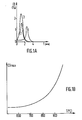
- FIGS. 1A, 1 B and 1 C are schematic views of the carbon monoxide contents of the fumes according to the prior art and according to the invention.
- Figure 2 is a schematic vertical and longitudinal sectional view of an apparatus incineration according to the invention.
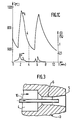
- FIG. 3 is a view in vertical and axial section, on a larger scale, of the nose of the lance for injecting oxygen and liquid of the device shown in FIG. 1.
- FIGS. 4 and 5 are diagrams illustrating the variation of the temperature in the incineration apparatus as a function of time, in the absence or in the presence of water spraying.
- Figures 6 and 7 are diagrams illustrating the variation of the oxygen injection and water spraying rates as a function of time, during different incineration cycles.
- FIG. 1A represents three records of the rate of carbon monoxide in the fumes of incinerators of known type with discontinuous loading and with strong combustion, as a function of time, the charge being introduced at t - o.
- Curves 1, 2 and 3 relate to the hearth temperatures during the introduction of the waste, respectively 680 ° C, 800 ° C and 900 ° C.
- Fig. 1B is a curve representing the variations in the maximum rate of carbon monoxide in the fumes as a function of the temperature of the hearth during the introduction, this curve showing the very rapid increase in the rate of carbon monohyde beyond 750 ° C.
- FIG. 1C represents on curve 5 the variations in the rate of carbon monoxide in the fumes leaving the oven, after application of the process according to the invention, a charge being introduced at t - 0 and another charge at t - 4 min .
- Curve 4 represents the correlative variations in hearth temperature. The charges are introduced at a hearth temperature of the order of 650 ° C. to 700 ° C., the temperature lowering, in approximately 1 min, to around 600 ° C., then rising in approximately thirty seconds, to a temperature of the order of 900 ° C to 950 ° C, temperature at which a very high flow rate of water injection causes the temperature to drop rapidly.
- the maximum CO level is located approximately halfway between the portion of curve 4 between 600 ° C and 900 ° C (around 800 ° C), the CO level having already dropped to approximately 0.1% when the temperature is maximum. In any event, the CO concentration is not greater than 0.5% when it was greater than 1.3 in FIG. 1A (prior art).
- the waste incineration apparatus of FIG. 2 comprises an oven 1, of any known type, provided with at least one burner not shown and into which are introduced, in a discontinuous manner, 2 waste to burn.
- a lance 3 for injecting pure oxygen and spraying a liquid such as, for example, water.
- the lance 3 has a hollow cylindrical body whose bore 4 communicates with the internal front face 5 of the lance 3 via a convergent-divergent 6.
- the bore 4 is connected, by a pipe 7, to a source of pure oxygen 8 and on the pipe 7 is connected a device 9 for adjusting the oxygen flow rate.
- the lance 3 also contains an axial pipe 10 for spraying liquid, such as water, which extends over almost the entire length of the lance 3 and the end of which is preferably situated in the divergent downstream part.
- This water spray pipe 10 communicates with a source of pressurized water 11 by means of a flow control device 12.
- a thermal probe (13) makes it possible to measure the temperature T in the oven and control, by comparison of the measured value with a setpoint Tc, the opening of the liquid valve when T> Te and the closing when T ⁇ Tc. It is also possible to provide several set values triggering flow rates of different values of the liquid (see below).
- the waste is placed in a primary chamber 15, partially separated from a secondary chamber 16 by a wall 18 forming a baffle with a second wall 19 and from which the fumes leave towards a discharge duct 17.
- water is also sprayed during the incineration cycle.
- the oxygen injected into the furnace has the advantage of maintaining a chemically active atmosphere around the waste being volatilized, which accelerates combustion.
- the liquid, such as water, which is sprayed mechanically or pneumatically with oxygen makes it possible to limit the heating of the hearth because by vaporizing above the charge, it acts as a heat sink vis-à-vis it.
- the sprayed liquid can allow either blocking of the soot particles by mechanical effect and, consequently, the total suppression of pollution, or the chemical activation of combustion by contribution of active radio species.
- the liquid can very advantageously consist of liquid waste to be destroyed.
- the different time periods to and t1 and the injection rates are preset so as to optimize the operation of the incineration device implementing the method.
- Figures 4 and 5 show the variation of the temperature T inside the oven as a function of time t, respectively with water injection (curve I) and without water injection (curve II).
- curve I water injection
- curve II water injection
- Figure 5 illustrates more particularly the very rapid influence of water. Indeed, the parts of the curve in solid lines were obtained with doping with oxygen and water, while the parts in dotted lines correspond to stops of injection of water.
- curve l ' the results were obtained with a load of 3 kg PCI 16750 kJ / kg (4000 kcal / kg), for an incineration cycle time of 6 min, the liquid to be injected being water at a flow rate of 100 I / h and for a period of time t 1 equal to the oxygen injection period to, ie 5 min.
- the device 12 for adjusting the water flow rate is connected to a thermal probe 13 placed in the oven 1, to adjust the flow rate of the water injected as a function of the temperature prevailing in the oven.
- a thermal probe 13 placed in the oven 1, to adjust the flow rate of the water injected as a function of the temperature prevailing in the oven.
- an oxygen injection was carried out during a period tO of 12 min, in two phases, namely a first phase at high flow rate for 6 min and then a second phase at low flow rate for 6 min, as indicated in FIGS. 5 and 6.
- the water injection is carried out for a period of time t 1 always less than or equal to tO with the following characteristics: very large water flow (170 I / h) in pulses of 30 s triggered if the temperature T in the oven exceeds 900 ° C, large flow (100 l / h) for an oven temperature between 850 ° C and 900 ° C and low flow (70 l / h) for an oven temperature between 850 ° C and 750 ° C.
- FIGS. 6 and 7 illustrate the cycles obtained, the cycle represented in FIG. 6 corresponding to waste very easy to incinerate while that represented in FIG. 7 corresponds to waste very difficult to incinerate.
- the curves in solid line correspond to the variation of the flow of oxygen as a function of time while those in broken line correspond to the flow of water during each cycle.
Landscapes
- Engineering & Computer Science (AREA)
- Chemical & Material Sciences (AREA)
- Combustion & Propulsion (AREA)
- Mechanical Engineering (AREA)
- General Engineering & Computer Science (AREA)
- Incineration Of Waste (AREA)
- Processing Of Solid Wastes (AREA)
- Air Supply (AREA)
- Gasification And Melting Of Waste (AREA)
- Control Of Temperature (AREA)
Claims (7)
Priority Applications (1)
| Application Number | Priority Date | Filing Date | Title |
|---|---|---|---|
| AT85402380T ATE34450T1 (de) | 1984-12-05 | 1985-12-03 | Abfallverbrennungsverfahren mit temperaturkontrolle. |
Applications Claiming Priority (2)
| Application Number | Priority Date | Filing Date | Title |
|---|---|---|---|
| FR8418508 | 1984-12-05 | ||
| FR8418508A FR2574159B1 (fr) | 1984-12-05 | 1984-12-05 | Procede d'incineration de dechets a temperature controlee |
Publications (2)
| Publication Number | Publication Date |
|---|---|
| EP0186561A1 EP0186561A1 (de) | 1986-07-02 |
| EP0186561B1 true EP0186561B1 (de) | 1988-05-18 |
Family
ID=9310236
Family Applications (1)
| Application Number | Title | Priority Date | Filing Date |
|---|---|---|---|
| EP85402380A Expired EP0186561B1 (de) | 1984-12-05 | 1985-12-03 | Abfallverbrennungsverfahren mit Temperaturkontrolle |
Country Status (10)
| Country | Link |
|---|---|
| US (1) | US4630555A (de) |
| EP (1) | EP0186561B1 (de) |
| JP (1) | JPS62501437A (de) |
| AT (1) | ATE34450T1 (de) |
| AU (1) | AU582820B2 (de) |
| CA (1) | CA1253397A (de) |
| DE (1) | DE3562821D1 (de) |
| ES (1) | ES8701951A1 (de) |
| FR (1) | FR2574159B1 (de) |
| WO (1) | WO1986003575A1 (de) |
Families Citing this family (20)
| Publication number | Priority date | Publication date | Assignee | Title |
|---|---|---|---|---|
| FR2574159B1 (fr) * | 1984-12-05 | 1987-01-30 | Air Liquide | Procede d'incineration de dechets a temperature controlee |
| US4957050A (en) * | 1989-09-05 | 1990-09-18 | Union Carbide Corporation | Combustion process having improved temperature distribution |
| US5000102A (en) * | 1989-12-21 | 1991-03-19 | Union Carbide Industrial Gases Technology Corporation | Method for combusting wet waste |
| DE4026245A1 (de) * | 1990-08-18 | 1992-02-20 | Hpm Technocommerz Technologie | Verfahren zur thermischen behandlung von abfaellen und reststoffen |
| US5018458A (en) * | 1990-09-12 | 1991-05-28 | Zimpro Passavant Environmental Systems, Inc. | Furnace combustion zone temperature control method |
| DE4031493C2 (de) * | 1990-10-05 | 1994-12-08 | Rwe Entsorgung Ag | Verfahren und Vorrichtung zur Verbrennung von Abfällen |
| US5052310A (en) * | 1991-01-22 | 1991-10-01 | Air Products And Chemicals, Inc. | Solid waste-to-steam incinerator capacity enhancement by combined oxygen enrichment and liquid quench |
| US5188042A (en) * | 1991-04-18 | 1993-02-23 | Praxair Technology, Inc. | Fluid waste burner system |
| US5129335A (en) * | 1991-04-18 | 1992-07-14 | Union Carbide Industrial Gases Technology Corporation | Fluid waste burner system |
| US5090340A (en) * | 1991-08-02 | 1992-02-25 | Burgess Donald A | Plasma disintegration for waste material |
| US5271340A (en) * | 1991-11-05 | 1993-12-21 | Rineco Chemical Industries | Apparatus and methods for burning waste, and waste slurries |
| US5353720A (en) * | 1993-02-12 | 1994-10-11 | Berg John E | Refuse incinerator |
| US5405537A (en) * | 1993-03-26 | 1995-04-11 | Air Products And Chemicals, Inc. | Process for combusting dewatered sludge waste in a municipal solid waste incinerator |
| DE4404418C2 (de) * | 1994-02-11 | 1997-10-23 | Martin Umwelt & Energietech | Verfahren zum Verbrennen von Brenngut, insbesondere Müll |
| US5752452A (en) * | 1996-10-25 | 1998-05-19 | Praxair Technology, Inc. | Apparatus and method for oxygen lancing in a multiple hearth furnace |
| EP0918192A1 (de) * | 1997-11-21 | 1999-05-26 | Quilldale Investments Limited | Verfahren zur Entsorgung von Abfallstoffen |
| US6685464B2 (en) * | 2001-03-28 | 2004-02-03 | L'Air Liquide - Societe Anonyme à Directoire et Conseil de Surveillance pour l'Etude et l'Exploitation des Procedes Georges Claude | High velocity injection of enriched oxygen gas having low amount of oxygen enrichment |
| ITBO20010207A1 (it) * | 2001-04-06 | 2002-10-06 | Itea Spa | Procedimento perfezionato per il trattamento di materiali, nonche' impianto e reattore per l'attuazione di detto procedimento |
| US7273366B1 (en) * | 2003-10-28 | 2007-09-25 | Soil-Therm Equipment, Inc. | Method and apparatus for destruction of vapors and waste streams |
| US7270539B1 (en) * | 2003-10-28 | 2007-09-18 | Soil-Therm Equipment, Inc. | Method and apparatus for destruction of vapors and waste streams using flash oxidation |
Family Cites Families (15)
| Publication number | Priority date | Publication date | Assignee | Title |
|---|---|---|---|---|
| US2829610A (en) * | 1955-05-31 | 1958-04-08 | Paskowski Michael | Incinerators |
| US2919980A (en) * | 1957-10-22 | 1960-01-05 | Koppers Co Inc | Apparatus for gasification of finely divided solid or liquid fuels |
| FR1473583A (fr) * | 1966-03-30 | 1967-03-17 | Von Roll Ag | Procédé pour brûler des combustibles de rebut, en particulier d'ordures ménagères, ainsi que four de combustion pour la mise en oeuvre de ce procédé |
| US3860384A (en) * | 1972-05-25 | 1975-01-14 | Intelcon Rad Tech | Method to control NOX formation in fossil-fueled boiler furnaces |
| DE2404484A1 (de) * | 1974-01-31 | 1975-08-14 | Hezinger Karlheinz | Vorrichtung zur verbesserung der vollstaendigen verbrennung in oefen, verbrennungsvorrichtungen o.dgl. |
| FR2293682A1 (fr) * | 1974-12-05 | 1976-07-02 | Hitz Henri | Four a eau |
| JPS521632A (en) * | 1975-06-24 | 1977-01-07 | Haibiruka Kk | Method and device of oxygen combustion |
| CH583881A5 (de) * | 1975-07-04 | 1977-01-14 | Von Roll Ag | |
| US4052138A (en) * | 1976-03-08 | 1977-10-04 | Gieck Joseph F | Method of firing coal boiler to produce secondary fuel gas |
| JPS5442867A (en) * | 1977-09-12 | 1979-04-05 | Hitachi Zosen Corp | Method of controlling temperature of furnace wall of garbage furnace |
| DE2950526A1 (de) * | 1979-12-15 | 1981-06-19 | Gertrud 7000 Stuttgart Alb | Verbrennungsofen |
| US4354440A (en) * | 1980-11-06 | 1982-10-19 | Environmental Control Products, Inc. | Underfire air and steam system and incinerating process for a controlled starved-air incinerator |
| US4444127A (en) * | 1982-07-23 | 1984-04-24 | Spronz Incinerator Corp. | Incinerator |
| JPS5925335A (ja) * | 1982-07-30 | 1984-02-09 | Kitamura Gokin Seisakusho:Kk | Pcbの無害化処理装置 |
| FR2574159B1 (fr) * | 1984-12-05 | 1987-01-30 | Air Liquide | Procede d'incineration de dechets a temperature controlee |
-
1984
- 1984-12-05 FR FR8418508A patent/FR2574159B1/fr not_active Expired
-
1985
- 1985-12-03 AT AT85402380T patent/ATE34450T1/de not_active IP Right Cessation
- 1985-12-03 WO PCT/FR1985/000347 patent/WO1986003575A1/fr not_active Ceased
- 1985-12-03 JP JP60505339A patent/JPS62501437A/ja active Pending
- 1985-12-03 US US06/860,194 patent/US4630555A/en not_active Expired - Lifetime
- 1985-12-03 DE DE8585402380T patent/DE3562821D1/de not_active Expired
- 1985-12-03 EP EP85402380A patent/EP0186561B1/de not_active Expired
- 1985-12-04 ES ES549572A patent/ES8701951A1/es not_active Expired
- 1985-12-05 CA CA000496980A patent/CA1253397A/fr not_active Expired
-
1986
- 1986-02-05 AU AU53219/86A patent/AU582820B2/en not_active Ceased
Also Published As
| Publication number | Publication date |
|---|---|
| EP0186561A1 (de) | 1986-07-02 |
| ATE34450T1 (de) | 1988-06-15 |
| FR2574159A1 (fr) | 1986-06-06 |
| DE3562821D1 (en) | 1988-06-23 |
| US4630555A (en) | 1986-12-23 |
| JPS62501437A (ja) | 1987-06-11 |
| ES549572A0 (es) | 1986-12-01 |
| WO1986003575A1 (fr) | 1986-06-19 |
| ES8701951A1 (es) | 1986-12-01 |
| AU5321986A (en) | 1987-08-06 |
| AU582820B2 (en) | 1989-04-13 |
| CA1253397A (fr) | 1989-05-02 |
| FR2574159B1 (fr) | 1987-01-30 |
Similar Documents
| Publication | Publication Date | Title |
|---|---|---|
| EP0186561B1 (de) | Abfallverbrennungsverfahren mit Temperaturkontrolle | |
| EP1144320B1 (de) | Verfahren un vorrichtung zum verbrennen und verglasen von abfällen, insbesondere radioaktiven abfällen | |
| CA2797168C (fr) | Four a flamme et procede de regulation de la combustion dans un four a flamme | |
| EP0522919B1 (de) | Verfahren und Einrichtung für die Thermolyse von Industrie- und/oder Haushaltsmüll | |
| EP0012091A1 (de) | Verfahren und Anlage zur Behandlung von Industriemüll | |
| US3942455A (en) | Incinerator and method | |
| FR2687765A1 (fr) | Procede et dispositif de controle de l'auto-combustion dans les installations de cremation. | |
| EP0485255B2 (de) | Verfahren und Vorrichtung zur Herstellung von einem festen Brennstoff ausgehend von brennbaren Abfällen | |
| EP0495710B1 (de) | Anlage zur Wärmeerzeugung mit Entschwefelungsvorrichtung durch regenerierbare Absorptionsmittel | |
| FR2463893A1 (fr) | Procede et appareil d'incineration auto-entretenue d'agglomeres combustibles facilement friables a forte teneur en eau | |
| FR2575271A1 (fr) | Appareil d'incineration et de fusion | |
| EP1247046B1 (de) | Verfahren und vorrichtung zur selbstverbrennung von öligen organischen abfällen mit einem tangentialen heizofen | |
| FR2721689A1 (fr) | Procédé et incinérateur pour incinérer les déchets hospitaliers et analogues. | |
| EP0593671A1 (de) | Verfahren zur verbrennung von organischen abfällen | |
| EP0694600B1 (de) | Verfahren und Vorrichtung für die Herstellung von Brennstoffen | |
| EP0673887B1 (de) | Verfahren zum Verglasen von Produkten in Stücken oder feste Teile | |
| WO2011157913A1 (fr) | Installation de production et de traitement de fumees | |
| FR2761458A1 (fr) | Incinerateur de dechets liquides, pateux et solides | |
| FR2686146A1 (fr) | Incinerateurs de dechets a chambres verticales multiples. | |
| FR2458600A1 (fr) | Procede pour eliminer une matiere combustible enrobant des fragments solides et dispositif pour sa mise en oeuvre | |
| EP4163026B1 (de) | Anlage und verfahren zur vernichtung pyrotechnischer abfälle | |
| EP0336087A1 (de) | Verfahren und Vorrichtung zur Behandlung eines Gasstromes, der pyrophorischen Staub enthält | |
| EP0834042B1 (de) | Verfahren und anlage zur verbrennung von krankenhausabfällen | |
| FR2458752A1 (fr) | Procede d'incineration de dechets et incinerateur permettant la mise en oeuvre de ce procede | |
| EP0100702A1 (de) | Vorrichtung zur Entzündung von Sauerstofflanzen |
Legal Events
| Date | Code | Title | Description |
|---|---|---|---|
| PUAI | Public reference made under article 153(3) epc to a published international application that has entered the european phase |
Free format text: ORIGINAL CODE: 0009012 |
|
| 17P | Request for examination filed |
Effective date: 19851206 |
|
| AK | Designated contracting states |
Kind code of ref document: A1 Designated state(s): AT BE CH DE FR GB IT LI LU NL SE |
|
| 17Q | First examination report despatched |
Effective date: 19870225 |
|
| ITF | It: translation for a ep patent filed | ||
| GRAA | (expected) grant |
Free format text: ORIGINAL CODE: 0009210 |
|
| AK | Designated contracting states |
Kind code of ref document: B1 Designated state(s): AT BE CH DE FR GB IT LI LU NL SE |
|
| REF | Corresponds to: |
Ref document number: 34450 Country of ref document: AT Date of ref document: 19880615 Kind code of ref document: T |
|
| REF | Corresponds to: |
Ref document number: 3562821 Country of ref document: DE Date of ref document: 19880623 |
|
| GBT | Gb: translation of ep patent filed (gb section 77(6)(a)/1977) | ||
| PG25 | Lapsed in a contracting state [announced via postgrant information from national office to epo] |
Ref country code: LU Free format text: LAPSE BECAUSE OF NON-PAYMENT OF DUE FEES Effective date: 19881231 |
|
| PLBE | No opposition filed within time limit |
Free format text: ORIGINAL CODE: 0009261 |
|
| STAA | Information on the status of an ep patent application or granted ep patent |
Free format text: STATUS: NO OPPOSITION FILED WITHIN TIME LIMIT |
|
| 26N | No opposition filed | ||
| PGFP | Annual fee paid to national office [announced via postgrant information from national office to epo] |
Ref country code: AT Payment date: 19891108 Year of fee payment: 5 |
|
| PGFP | Annual fee paid to national office [announced via postgrant information from national office to epo] |
Ref country code: CH Payment date: 19891123 Year of fee payment: 5 |
|
| PGFP | Annual fee paid to national office [announced via postgrant information from national office to epo] |
Ref country code: LU Payment date: 19891204 Year of fee payment: 5 |
|
| PG25 | Lapsed in a contracting state [announced via postgrant information from national office to epo] |
Ref country code: AT Effective date: 19901203 |
|
| PG25 | Lapsed in a contracting state [announced via postgrant information from national office to epo] |
Ref country code: LI Effective date: 19901231 Ref country code: CH Effective date: 19901231 |
|
| REG | Reference to a national code |
Ref country code: CH Ref legal event code: PL |
|
| ITTA | It: last paid annual fee | ||
| PGFP | Annual fee paid to national office [announced via postgrant information from national office to epo] |
Ref country code: GB Payment date: 19931116 Year of fee payment: 9 |
|
| PG25 | Lapsed in a contracting state [announced via postgrant information from national office to epo] |
Ref country code: GB Effective date: 19941203 |
|
| EAL | Se: european patent in force in sweden |
Ref document number: 85402380.1 |
|
| GBPC | Gb: european patent ceased through non-payment of renewal fee |
Effective date: 19941203 |
|
| PGFP | Annual fee paid to national office [announced via postgrant information from national office to epo] |
Ref country code: FR Payment date: 20001113 Year of fee payment: 16 |
|
| PGFP | Annual fee paid to national office [announced via postgrant information from national office to epo] |
Ref country code: SE Payment date: 20001120 Year of fee payment: 16 |
|
| PGFP | Annual fee paid to national office [announced via postgrant information from national office to epo] |
Ref country code: DE Payment date: 20001122 Year of fee payment: 16 |
|
| PGFP | Annual fee paid to national office [announced via postgrant information from national office to epo] |
Ref country code: NL Payment date: 20001123 Year of fee payment: 16 |
|
| PGFP | Annual fee paid to national office [announced via postgrant information from national office to epo] |
Ref country code: BE Payment date: 20001218 Year of fee payment: 16 |
|
| PG25 | Lapsed in a contracting state [announced via postgrant information from national office to epo] |
Ref country code: SE Free format text: LAPSE BECAUSE OF NON-PAYMENT OF DUE FEES Effective date: 20011204 |
|
| PG25 | Lapsed in a contracting state [announced via postgrant information from national office to epo] |
Ref country code: BE Free format text: LAPSE BECAUSE OF NON-PAYMENT OF DUE FEES Effective date: 20011231 |
|
| BERE | Be: lapsed |
Owner name: L' AIR LIQUIDE S.A. POUR L'ETUDE ET L'EXPLOITATION Effective date: 20011231 |
|
| PG25 | Lapsed in a contracting state [announced via postgrant information from national office to epo] |
Ref country code: NL Free format text: LAPSE BECAUSE OF NON-PAYMENT OF DUE FEES Effective date: 20020701 |
|
| PG25 | Lapsed in a contracting state [announced via postgrant information from national office to epo] |
Ref country code: DE Free format text: LAPSE BECAUSE OF NON-PAYMENT OF DUE FEES Effective date: 20020702 |
|
| EUG | Se: european patent has lapsed |
Ref document number: 85402380.1 |
|
| PG25 | Lapsed in a contracting state [announced via postgrant information from national office to epo] |
Ref country code: FR Free format text: LAPSE BECAUSE OF NON-PAYMENT OF DUE FEES Effective date: 20020830 |
|
| NLV4 | Nl: lapsed or anulled due to non-payment of the annual fee |
Effective date: 20020701 |
|
| REG | Reference to a national code |
Ref country code: FR Ref legal event code: ST |