EP0186573B1 - Detektorvorrichtung eines Wechselgetriebes für die Steuerung einer Betätigungsanlage einer Kupplung ab dem Betätigungsgestänge eines dazugehörigen Wechselgetriebes - Google Patents
Detektorvorrichtung eines Wechselgetriebes für die Steuerung einer Betätigungsanlage einer Kupplung ab dem Betätigungsgestänge eines dazugehörigen Wechselgetriebes Download PDFInfo
- Publication number
- EP0186573B1 EP0186573B1 EP85402462A EP85402462A EP0186573B1 EP 0186573 B1 EP0186573 B1 EP 0186573B1 EP 85402462 A EP85402462 A EP 85402462A EP 85402462 A EP85402462 A EP 85402462A EP 0186573 B1 EP0186573 B1 EP 0186573B1
- Authority
- EP
- European Patent Office
- Prior art keywords
- elements
- gear change
- clutch
- control
- limit positions
- Prior art date
- Legal status (The legal status is an assumption and is not a legal conclusion. Google has not performed a legal analysis and makes no representation as to the accuracy of the status listed.)
- Expired
Links
Images
Classifications
-
- B—PERFORMING OPERATIONS; TRANSPORTING
- B60—VEHICLES IN GENERAL
- B60W—CONJOINT CONTROL OF VEHICLE SUB-UNITS OF DIFFERENT TYPE OR DIFFERENT FUNCTION; CONTROL SYSTEMS SPECIALLY ADAPTED FOR HYBRID VEHICLES; ROAD VEHICLE DRIVE CONTROL SYSTEMS FOR PURPOSES NOT RELATED TO THE CONTROL OF A PARTICULAR SUB-UNIT
- B60W30/00—Purposes of road vehicle drive control systems not related to the control of a particular sub-unit, e.g. of systems using conjoint control of vehicle sub-units
- B60W30/18—Propelling the vehicle
-
- B—PERFORMING OPERATIONS; TRANSPORTING
- B60—VEHICLES IN GENERAL
- B60W—CONJOINT CONTROL OF VEHICLE SUB-UNITS OF DIFFERENT TYPE OR DIFFERENT FUNCTION; CONTROL SYSTEMS SPECIALLY ADAPTED FOR HYBRID VEHICLES; ROAD VEHICLE DRIVE CONTROL SYSTEMS FOR PURPOSES NOT RELATED TO THE CONTROL OF A PARTICULAR SUB-UNIT
- B60W10/00—Conjoint control of vehicle sub-units of different type or different function
- B60W10/02—Conjoint control of vehicle sub-units of different type or different function including control of driveline clutches
-
- B—PERFORMING OPERATIONS; TRANSPORTING
- B60—VEHICLES IN GENERAL
- B60W—CONJOINT CONTROL OF VEHICLE SUB-UNITS OF DIFFERENT TYPE OR DIFFERENT FUNCTION; CONTROL SYSTEMS SPECIALLY ADAPTED FOR HYBRID VEHICLES; ROAD VEHICLE DRIVE CONTROL SYSTEMS FOR PURPOSES NOT RELATED TO THE CONTROL OF A PARTICULAR SUB-UNIT
- B60W10/00—Conjoint control of vehicle sub-units of different type or different function
- B60W10/10—Conjoint control of vehicle sub-units of different type or different function including control of change-speed gearings
Definitions
- the invention relates to the control of an automatic clutch operating system from the shift lever of a gearbox associated with this clutch. It applies in particular but not exclusively to the case of motor vehicles.
- an automatic clutch operating system is a system adapted to maneuver a clutch by itself in the direction of engagement (torque transmission) or disengagement (interruption of torque transmission) and whose the implementation is controlled by a control device adapted to apply or not an activation signal to it.
- a control device adapted to apply or not an activation signal to it.
- a system comprises an operating means such as a motor which receives, or not, an activation signal, for example of the electrical type.
- a control device for activating and deactivating a automatic clutch operating system constituted by a gearshift lever of the “broken lever” type.
- the lever consists of two generally aligned sections, one of which is a maneuvering section subjected to the action of a user and a control section connected to a gearbox by an appropriate wheelhouse.
- the maneuvering section admits a movement with respect to the control section; these two sections include two respective electrical contacts adapted to establish a circuit (or on the contrary cut it) when the operating section tilts relative to the control section under the action of a user.
- clutch control devices of this type have drawbacks, in particular that of causing disengagement of the clutch in practice as soon as the gearshift lever is pressed, and this, whatever the direction of the stress: inadvertent disengagement operations may result, which may be detrimental to the good performance of the clutch, to safety and to comfort in the case of a motor vehicle.
- the end of disengagement of the clutch is generally controlled with insufficient precision to ensure gear changes with all the flexibility desired.
- the main object of the present invention is to overcome this drawback by means of a control adapted to act only when stressed in the direction of disengagement of the engaged speed. It is also intended to allow the clutch to remain disengaged until a new gear is engaged. It also aims to allow adequate control of a system for operating a clutch without excessive wear between the elements involved, that is to say a control which has a long service life.
- the invention provides for this purpose a speed change detection device for controlling an automatic maneuvering system of a clutch from the shift lever of a gearbox associated with this clutch, of the kind comprising a first linkage element, said downstream element, admitting a travel travel between two limit positions corresponding to the engagement of gears within the gearbox and a second linkage element, said upstream element, elastically coupled to the downstream element by means of return to a neutral position, and with which is associated a displacement indicator assembly controlling an activation circuit for said automatic operating system, characterized in that said displacement indicator assembly comprises locating means adapted to identify, when the downstream element is in one of its limit positions, the direction in which a displacement of the upstream element from its neutral position causes a movement of the downstream element towards its other limit position and authorization means adapted to selectively control the activation circuit with a view to disengaging the clutch when the upstream element moves in the aforementioned direction.
- the upstream element admits a travel of travel between two limit positions corresponding respectively to the limit positions of the downstream element, and the authorization means controlling the activation circuit when the upstream element moves between its limit positions.
- the invention more particularly recommends that said displacement indicator assembly is adapted to detect and indicate the presence or not of each of said elements in one of its limit positions so that disengagement of the clutch by said automatic operating system takes place when any one of said elements is situated between its extreme positions.
- a control device advantageously causes disengagement of the clutch as long as one of the two elements of the shift lever of a gearbox associated with the clutch has not reached one of its extreme positions.
- the invention thus proposes to focus on the positions of each of the two wheelhouse elements relative to a fixed part, a chassis in practice, rather than considering, as in the case of the abovementioned “broken levers”, the relative position of these elements.
- the invention therefore makes it possible that, where appropriate, the elements under consideration do not follow one another in the gearbox maneuvering wheelhouse. However, it recommends that the position of the elements considered be detected by the same position detector, whether optical or electrical mechanics, and that, to do this, said elements are adjacent.
- the invention particularly proposes that the elements considered are pivoting elements, preferably mounted side by side on the same shaft: these elements are advantageously mounted on the gear shift shaft of the gearbox.
- the position of the two elements considered is preferably detected by a probe applied against the slices of similar cams formed on these elements; in practice, the probe admits two main configurations corresponding respectively to the activation or not of the associated operating system and, in principle, only the ramps which the cams present in order to cause the probe to pass from one to the other of these configurations need to be identical on both cams.
- a sensor can be replaced, for example by a photoelectric cell receiving a beam intercepted or not by one or the other of the elements considered, by their peripheral profile or by the edge of windows which are provided there.
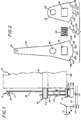
- FIGS 1 to 7 show an exemplary embodiment of a speed change detection device 10 according to the invention for activating or deactivating a system 11 for operating a clutch (not shown) during a change in the configuration of the steering linkage 12 of a gearbox 13.
- the gearbox 13 comprises a casing 13A and a gear shift shaft 14 of which one end 14A exits from said casing.
- the speed change detection device 10 is mounted on this end 14A.
- This speed change detection device 10 controls the state of the automatic clutch maneuvering system 11 which, not being in itself part of the invention, is here described and shown only very schematically.
- This system 10 can be of any suitable type; it may in particular be of the type described and represented in patent FR-2 523 743 filed on March 18, 1982 or its certificate of addition FR-2541 793 filed on February 25, 1983, in the name of the applicant.
- the system 11 comprises a jack 15, the retractable rod 16 of which is articulated at its end on a lever 17 with two arms forming a clutch release fork: its left end acts for example on a stop of clutch not shown.
- the speed change detection device 10 comprises two movable linkage elements, upstream 18 and downstream 19, coupled in movement by a coupling or elastic coupling member 20 as well as an assembly position or displacement indicator 21 adapted to cooperate with the elements 18 and 19 so as to control the state of a circuit 22 for activating the automatic clutch actuation system 11.
- the circuit 22 is for example a hydraulic circuit comprising a valve 23 whose state is fixed by the position indicator assembly; in the case where the automatic clutch operating system comprises an electric motor, the activation circuit alternatively comprises a power source and a switch whose state is fixed by the position indicator assembly 21.
- the linkage elements 18 and 19 are both pivotally mounted on the projecting end 14A of the gear shift shaft 14.
- One 18 of these elements in the form of a lever with two arms, has an orifice 24 by which it is freely engaged on the end 14A of the shaft 14 as well as a window 25 for the reception of the elastic coupling member 20; it further comprises, at one of its ends, an anchoring pin 26 intended to cooperate with an element further upstream in the maneuvering wheelhouse, such as a rod 27 shown in phantom in Figure 1.
- This element 18 is controlled in position by a user acting in practice on a gear lever 28 (see FIGS. 3 to 7) located quite upstream of the steering linkage 12: the element 18 constitutes within the device 10 a driving element or actuating element.
- the other element 19, in the form of a lever with a single arm, comprises an orifice 29 through which it is engaged and secured, by welding for example, on the end 14A of the shaft 14, preferably opposite the casing 13A of the gearbox relative to the element 18 so as to prevent the latter from being able to disengage from the end 14A by axial drift.
- the element 19 forming a driven or driving element for the gear shift shaft 14 further comprises a window 30 identical to the window 25 of the element 18, these windows 25 and 30 being arranged in the same way vis- with respect to orifices 24 and 29 respectively.
- the elastic coupling of these elements 18 and 19 in pivoting is obtained by an elastic coupling means (forming a return to neutral position) engaged simultaneously in recesses made in these elements.
- a spring 20 is engaged simultaneously in the windows 25 and 30, preferably being prestressed while simultaneously pressing on the substantially radial edges which these windows present.
- the elastic coupling means is a rubber pad, billage, or the like. It should be noted that it is sufficient for this coupling means to be able to come to bear on each of the linkage elements parallel to the direction of relative movement between them. It can therefore be received in simple recesses formed in these elements, so as for example to avoid any escape of this coupling means with respect to these wheelhouse elements.
- the window 25 is formed opposite the lug 26 relative to the orifice 24 and that the shortest arm of the element 18, in which this window 25 is formed substantially the same profile as the single-arm lever that constitutes the element 19.
- the profiles of the elements 18 and 19 are substantially superposed axially (neutral relative position).
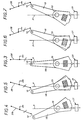
- the elements 18 and 19 admit around the gear shift shaft 14 the same angular movement between two limit positions (see FIGS. 4 and 7) for which a gear is engaged in the gearbox.
- the positions are arranged symmetrically with respect to an axial reference plane shown diagrammatically at P in FIGS. 3 to 7.
- a cylinder 31 axially oriented forming a probe, which is fixed on rods 32 adapted to penetrate more or less deeply, parallel to the plane P, in a housing 32A fixed relative to the gearbox 13A or to the chassis supporting it.
- the probe 31 forms with its sliding rods 32 and the housing 32A the aforementioned displacement indicator assembly 21; depending on the degree of penetration of the rods 32 this indicator assembly admits two reference configurations for which it is adapted to cause, or not, the activation of the automatic clutch actuation system 11.
- the degree of penetration of the rods 32 is controlled by the cam-shaped profiles presented by the sections 18A and 19A of the elements 18 and 19.
- These sections have two lateral support areas 33A and 33B or 34A and 34B, preferably centered on the shaft 14, on either side of a projecting cam area 33C or 34C, preferably concentric with the abovementioned bearing pads, to which they are connected by transition ramps 33D and 33E or 34D and 34E.
- These projecting cam zones advantageously have in their middle notches 33F or 34F forming a notch.
- the protruding cam zones occupy with the transition ramps an angular sector substantially equal, although, in practice, slightly less, than the angular movement admitted by the elements 18 and 19 between their limit positions.
- the elements 18 and 19 are aligned along the plane P.
- Their cam profiles 18A and 19A are axially superimposable and the cylinder 31 forming a probe is engaged in the dead center notches 33F or 34F and the rods 32 are pressed into the housing 32A: there is a command to disengage the associated clutch.
- the probe 31 When a gear is engaged, as shown in FIGS. 4 and 7, the probe 31 is in abutment against a lateral bearing surface of each element 33A and 34A or 33B and 34B, and the rods 32 are in configuration of extension: there is a clutch engagement command.
- the probe is also in contact or almost with the neighboring transition ramps whereby a slight rotation of any of the elements 18 and 19 is sufficient to cause, thanks to the associated ramp, a depression of the probe and its rods in the housing which causes a clutch disengagement control.
- the spring 20 under prestressing allows such an angular offset between the elements 18 and 19 only beyond a minimum torque applied to the element 19, which eliminates parasites.
- the elasticity of the spring 20 however allows that, beyond a minimum force, the element 18 can start to rotate (see FIG. 5), thus causing the probe to sink; this controls disengagement of the clutch, hence the suppression of the retaining torque applied by the latter to the input of the gearbox: the gearshift shaft is released, as well as the element 19 and the spring 20 causes them to catch up with their angular delay relative to the actuating element 18.
- the upstream actuating element 18 reaches without resistance in its other limit position, but it sometimes happens that the corresponding speed is difficult to engage: the gearshift shaft therefore remains below its final position. It is the same for element 19 which, thanks to the compressibility of spring 20, can take a slight delay on the element 18. As it appears in FIG. 6, the element 19 maintains the probe in the depressed condition: the clutch therefore remains disengaged as long as the gearshift shaft does not did not actually reach final configuration.
- the cam profile of the upstream element 18 constitutes, thanks to its ramps 33D and 33E, marking means adapted to identify the direction in which the upstream element must move, from from its neutral position relative to the downstream element, to cause movement of the downstream element from one of its limit positions towards the other; in fact, when the upstream element is in one of its limit positions, there is only one ramp in the vicinity of the probe, arranged relative to the latter in the direction of movement towards the other limit position; these ramps constitute, with the probe 31 and the section 33C, authorization means suitable for controlling the activation circuit 22 when the upstream element moves in the "right direction.”
- the role of the lateral areas of these sections is mainly to prevent the probe and its rods 32 from protruding too much from the housing 32A: it may suffice that there are only end areas on a single element , or even on no element if the rods 32 are sufficiently retained in the housing in the event of extension. In a variant not shown, it is the lateral areas of the edges of the elements 18 and 19 which are projecting.
- the above description has been offered for information only and that many variant embodiments can be proposed by those skilled in the art without departing from the scope of the invention, so far as concerns the shape of the wheelhouse elements considered (bent levers or other) only with regard to the nature of the associated displacement detector assembly and of its means of location and authorization.
- the coupling member can be of any suitable nature.
- the elements with which the displacement indicator assembly is associated can be dissociated from one another and with respect to the gearshift shaft; they can be rods in linear movement: the displacement indicator assembly can be split so as to separately test the presence or not of each of the elements in a limit position.
- the displacement indicator assembly is adapted to test the presence or not of the only upstream element in a limit position.
- This displacement indicator assembly can be of any kind; it can include an electronic sensor (analog, potentiometer, Hall effect sensor, inductive sensor for example) or also an optical sensor with holes in the elements which only come into alignment with a light source simultaneously if these elements are in the appropriate position .
Landscapes
- Engineering & Computer Science (AREA)
- Transportation (AREA)
- Mechanical Engineering (AREA)
- Chemical & Material Sciences (AREA)
- Combustion & Propulsion (AREA)
- Automation & Control Theory (AREA)
- Control Of Transmission Device (AREA)
Claims (12)
Applications Claiming Priority (2)
| Application Number | Priority Date | Filing Date | Title |
|---|---|---|---|
| FR8419082A FR2574720B1 (fr) | 1984-12-13 | 1984-12-13 | Dispositif de detection de changement de vitesse pour la commande d'un systeme de manoeuvre d'un embrayage a partir de la timonerie de manoeuvre d'une boite de vitesse associee |
| FR8419082 | 1984-12-13 |
Publications (2)
| Publication Number | Publication Date |
|---|---|
| EP0186573A1 EP0186573A1 (de) | 1986-07-02 |
| EP0186573B1 true EP0186573B1 (de) | 1988-07-27 |
Family
ID=9310561
Family Applications (1)
| Application Number | Title | Priority Date | Filing Date |
|---|---|---|---|
| EP85402462A Expired EP0186573B1 (de) | 1984-12-13 | 1985-12-11 | Detektorvorrichtung eines Wechselgetriebes für die Steuerung einer Betätigungsanlage einer Kupplung ab dem Betätigungsgestänge eines dazugehörigen Wechselgetriebes |
Country Status (3)
| Country | Link |
|---|---|
| EP (1) | EP0186573B1 (de) |
| DE (1) | DE3563935D1 (de) |
| FR (1) | FR2574720B1 (de) |
Families Citing this family (2)
| Publication number | Priority date | Publication date | Assignee | Title |
|---|---|---|---|---|
| FR2643316B1 (fr) * | 1989-02-17 | 1993-09-10 | Valeo | Dispositif de detection de vitesse pour la commande d'un embrayage associe a une boite de vitesses |
| US5490434A (en) * | 1994-01-28 | 1996-02-13 | Grand Haven Stamped Products | Vehicle transfer case shifter system |
Family Cites Families (5)
| Publication number | Priority date | Publication date | Assignee | Title |
|---|---|---|---|---|
| US1685502A (en) * | 1925-02-09 | 1928-09-25 | Twin Disc Clutch Co | Clutch and transmission mechanism |
| FR1115791A (fr) * | 1954-12-06 | 1956-04-30 | Citroen Sa Andre | Perfectionnements aux mécanismes d'embrayage |
| US3993175A (en) * | 1974-10-23 | 1976-11-23 | Fiat-Allis Construction Machinery, Inc. | Control lever assembly for power shift transmission and modulating clutch |
| DE3229369A1 (de) * | 1982-08-06 | 1984-02-09 | Sachs Systemtechnik Gmbh | Reibungskupplung fuer brennkraftmaschinen-getriebene fahrzeuge |
| US4610335A (en) * | 1982-11-10 | 1986-09-09 | Honda Giken Kogyo Kabushiki Kaisha | Control device for clutch and transmission in vehicles |
-
1984
- 1984-12-13 FR FR8419082A patent/FR2574720B1/fr not_active Expired
-
1985
- 1985-12-11 EP EP85402462A patent/EP0186573B1/de not_active Expired
- 1985-12-11 DE DE8585402462T patent/DE3563935D1/de not_active Expired
Also Published As
| Publication number | Publication date |
|---|---|
| FR2574720B1 (fr) | 1987-02-27 |
| FR2574720A1 (fr) | 1986-06-20 |
| DE3563935D1 (en) | 1988-09-01 |
| EP0186573A1 (de) | 1986-07-02 |
Similar Documents
| Publication | Publication Date | Title |
|---|---|---|
| EP0189338B1 (de) | Vorrichtung zur Detektion eines Gangwechsels zum Steuern einer mit einem Getriebe verbundenen Kupplung | |
| EP0220092B1 (de) | Steuereinrichtung für ein Kupplungsmittel, z.B. eine schaltbare Kupplung oder ein Getriebe oder eine Bremse oder dergleichen | |
| WO2013007924A2 (fr) | Dispositif pour la commande d'une boite de vitesses et d'un frein de stationnement d'un vehicule automobile au moyen d'un levier de manoeuvre commun | |
| FR2964925A1 (fr) | Frein de parc a verrouillage automatique | |
| FR2530757A1 (fr) | Commande d'embrayage a friction | |
| EP0624741B1 (de) | Gangschaltungseinrichtung für ein automatisches Kraftfahrzeuggetriebe | |
| EP0186573B1 (de) | Detektorvorrichtung eines Wechselgetriebes für die Steuerung einer Betätigungsanlage einer Kupplung ab dem Betätigungsgestänge eines dazugehörigen Wechselgetriebes | |
| EP0383688B1 (de) | Vorrichtung zum Detektieren des geschalteten Ganges eines Handschaltgetriebes, gekoppelt mit einem Schaltmechanismus für eine automatische Kupplung | |
| EP0420738B1 (de) | Gestänge zur Kraftübertragung für Kraftfahrzeuge | |
| EP0186537B1 (de) | Scheibenbremse | |
| EP0734496B1 (de) | Automatisch nachstellbare strebe für eine trommelbremse | |
| FR2704616A1 (fr) | Dispositif de changement de vitesse pour une boîte de vitesses d'un véhicule automobile. | |
| FR2797020A1 (fr) | Fourchette de changement de vitesse pour boite de vitesses d'un vehicule automobile | |
| FR2735551A1 (fr) | Dispositif de verrouillage pour boite de vitesses mecanique | |
| EP0751322A1 (de) | Fahrzeug-Gangschalthebel mit Kraftaufnehmer | |
| FR2703422A1 (fr) | Dispositif de changement de vitesses pour une boîte de vitesses à engrenages d'un véhicule automobile. | |
| FR2611837A1 (fr) | Dispositif de commande d'embrayage avec pilotage | |
| EP0225211B1 (de) | Sicherheitseinrichtung für den Rückwärtsgang an einem gelenkigen Schalthebel | |
| EP1179463A1 (de) | Steuervorrichtung für eine elektrische Feststellbremse mit Wandlerelement | |
| FR2579703A1 (fr) | Butee de debrayage, notamment pour vehicule automobile | |
| FR2859006A1 (fr) | Dispositif de changement de vitesse, ensemble et vehicule automobile correpondants | |
| FR2782036A1 (fr) | Dispositif de commande manuelle d'un organe fonctionnel, associe a un levier, notamment le levier d'actionnement d'une boite de vitesses | |
| EP0013193B1 (de) | Mechanische Betätigung für Schaltkupplung | |
| EP0349368B1 (de) | Einstellbare Scheibenbremse | |
| EP1351835A1 (de) | Am lenkrad angeordnetes steuerungssystem für fahrzeug |
Legal Events
| Date | Code | Title | Description |
|---|---|---|---|
| PUAI | Public reference made under article 153(3) epc to a published international application that has entered the european phase |
Free format text: ORIGINAL CODE: 0009012 |
|
| AK | Designated contracting states |
Kind code of ref document: A1 Designated state(s): DE GB IT |
|
| 17P | Request for examination filed |
Effective date: 19860814 |
|
| 17Q | First examination report despatched |
Effective date: 19871116 |
|
| GRAA | (expected) grant |
Free format text: ORIGINAL CODE: 0009210 |
|
| AK | Designated contracting states |
Kind code of ref document: B1 Designated state(s): DE GB IT |
|
| PG25 | Lapsed in a contracting state [announced via postgrant information from national office to epo] |
Ref country code: IT Free format text: LAPSE BECAUSE OF FAILURE TO SUBMIT A TRANSLATION OF THE DESCRIPTION OR TO PAY THE FEE WITHIN THE PRESCRIBED TIME-LIMIT;WARNING: LAPSES OF ITALIAN PATENTS WITH EFFECTIVE DATE BEFORE 2007 MAY HAVE OCCURRED AT ANY TIME BEFORE 2007. THE CORRECT EFFECTIVE DATE MAY BE DIFFERENT FROM THE ONE RECORDED. Effective date: 19880727 |
|
| REF | Corresponds to: |
Ref document number: 3563935 Country of ref document: DE Date of ref document: 19880901 |
|
| GBT | Gb: translation of ep patent filed (gb section 77(6)(a)/1977) | ||
| PLBE | No opposition filed within time limit |
Free format text: ORIGINAL CODE: 0009261 |
|
| STAA | Information on the status of an ep patent application or granted ep patent |
Free format text: STATUS: NO OPPOSITION FILED WITHIN TIME LIMIT |
|
| 26N | No opposition filed | ||
| PGFP | Annual fee paid to national office [announced via postgrant information from national office to epo] |
Ref country code: GB Payment date: 19921127 Year of fee payment: 8 |
|
| PGFP | Annual fee paid to national office [announced via postgrant information from national office to epo] |
Ref country code: DE Payment date: 19921231 Year of fee payment: 8 |
|
| PG25 | Lapsed in a contracting state [announced via postgrant information from national office to epo] |
Ref country code: GB Effective date: 19931211 |
|
| GBPC | Gb: european patent ceased through non-payment of renewal fee |
Effective date: 19931211 |
|
| PG25 | Lapsed in a contracting state [announced via postgrant information from national office to epo] |
Ref country code: DE Effective date: 19940901 |