EP0186581A1 - Motoventilateur, notamment pour véhicule automobile, fixé sur des bras supports solidaires de la carrosserie - Google Patents
Motoventilateur, notamment pour véhicule automobile, fixé sur des bras supports solidaires de la carrosserie Download PDFInfo
- Publication number
- EP0186581A1 EP0186581A1 EP85402509A EP85402509A EP0186581A1 EP 0186581 A1 EP0186581 A1 EP 0186581A1 EP 85402509 A EP85402509 A EP 85402509A EP 85402509 A EP85402509 A EP 85402509A EP 0186581 A1 EP0186581 A1 EP 0186581A1
- Authority
- EP
- European Patent Office
- Prior art keywords
- fixed
- connector
- motor
- electric motor
- support arms
- Prior art date
- Legal status (The legal status is an assumption and is not a legal conclusion. Google has not performed a legal analysis and makes no representation as to the accuracy of the status listed.)
- Granted
Links
Images
Classifications
-
- B—PERFORMING OPERATIONS; TRANSPORTING
- B60—VEHICLES IN GENERAL
- B60H—ARRANGEMENTS OF HEATING, COOLING, VENTILATING OR OTHER AIR-TREATING DEVICES SPECIALLY ADAPTED FOR PASSENGER OR GOODS SPACES OF VEHICLES
- B60H1/00—Heating, cooling or ventilating devices
- B60H1/00457—Ventilation unit, e.g. combined with a radiator
- B60H1/00464—The ventilator being of the axial type
-
- F—MECHANICAL ENGINEERING; LIGHTING; HEATING; WEAPONS; BLASTING
- F01—MACHINES OR ENGINES IN GENERAL; ENGINE PLANTS IN GENERAL; STEAM ENGINES
- F01P—COOLING OF MACHINES OR ENGINES IN GENERAL; COOLING OF INTERNAL-COMBUSTION ENGINES
- F01P5/00—Pumping cooling-air or liquid coolants
- F01P5/02—Pumping cooling-air; Arrangements of cooling-air pumps, e.g. fans or blowers
-
- F—MECHANICAL ENGINEERING; LIGHTING; HEATING; WEAPONS; BLASTING
- F01—MACHINES OR ENGINES IN GENERAL; ENGINE PLANTS IN GENERAL; STEAM ENGINES
- F01P—COOLING OF MACHINES OR ENGINES IN GENERAL; COOLING OF INTERNAL-COMBUSTION ENGINES
- F01P2070/00—Details
- F01P2070/50—Details mounting fans to heat-exchangers
Definitions
- the present invention relates to a fan motor, in particular for a motor vehicle.
- An object of the invention is to provide a fan for which the assembly on the body and the electrical connection can be carried out simultaneously in a single direction.
- the subject of the invention is therefore a motor-driven fan, in particular for a motor vehicle, consisting of a propeller fixed on the shaft of an electric motor, the motor being fixed on the radial support arms whose external ends are fixed to a surrounding frame the electric motor and the propeller, characterized in that electric wires connect the electric motor to an electric connector, a first part of which is fixed to the frame and a second part is fixed to a part which is fixed to the body, according to the axis of one of the support arms, the first part of the connector being near the end of this support arm and in that the connection axis of the two parts of the connector is parallel to the direction of mounting of the fan on the integral parts of the body and in this that the second part of the connector is held elastically.
- At least one of the support arms of the fan is hollow so as to constitute a sheath for the electric wires passing inside of it from the electric motor to an opening located at near the end of this support arm and are connected to the first part of the electrical connector.
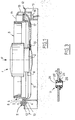
- Fig.1 represents a fan 1 comprising an electric motor 2 on the shaft (not shown) which is fixed a propeller 3, a frame 4 surrounding the engine and the propeller is made integral with the engine by means of support arms 5 extending substantially radially with respect to the axis of rotation of the propeller.
- the support arms 5 are fixed to the frame 4; and to the electric motor by means of fixing lugs 6 of the latter, the whole being fixed to the body by means of fixing means 7 of the screw-nut type or the like.
- the frame 4 comprises a circular wall 8 parallel to the axis of rotation of the propeller 3 so as to surround the blades of the propeller and a flange 9 formed integrally with the wall 8 and approximately perpendicular thereto , and extending towards the outside of this wall.
- the support arms have an almost cylindrical shape and their ends 10 are flattened and folded so as to come into contact with part of the external surface of the wall 8 and the lower surface of the flange 9.
- the flattened ends 10 are fixed to the flange 9 by fixing means 11, which will be described with reference to Fig.3, but can also be welded or glued to this flange.
- the fixing lugs 6 have come in material with the motor 2 and are rolled so as to partially surround the corresponding support arm. It is possible to reinforce this fixing by marking in the tab and the support arm at the end of rolling or any other known means.
- the fan 1 is fixedly mounted on parts 12 in the form of a square and integral with the body, by means of the ends 10 of the support arms fixed to the flange 9, the mounting being carried out in the direction F.
- Conductive wires 13 for supplying the electric motor 2 connect the latter to a first part 14 of an electric connector fixed to the frame 4 above the flange which has a cutout 15 so that the connection elements 14A of this part of the connector are accessible.
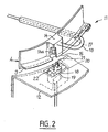
- This part of the connector can also have come in material with the frame 4 as shown in Fig.2.
- the conductive wires 13 pass inside one of the support arms comprising an orifice 16 near the motor 2 and an opening 17 located just before the folded and flattened end 10 so as to allow the conductive wires 13 to pass.
- the support arms 5 can have an aerodynamic shape without the existence of the conductive wires impairing their function.
- a second part 18 of the electrical connector is housed in a box 19 fixed under the part 12 secured to the body opposite the first part 14, the part 12 having a cutout 20 so as to have allow the connection elements to pass 21 of the second part of the connector.
- connection elements of the two parts are oriented in such a way that their connection takes place in the direction F of the mounting of the fan motor on the parts 12.
- the second part of the connector 18 is elastically stressed by four members elastic 22 disposed between its side walls and the inner wall of the housing 19. These elastic members have great rigidity to the forces exerted on the second part 18 in the direction F and a certain capacity of deformation in a plane perpendicular to this direction so as to obtain self-positioning of the connection elements when they are connected.
- the elastic members 12 are constituted by deformable tongues, elastomer members, springs or the like.
- Fig.3 shows an embodiment of the fastening means 11 of the frame 4 with the support arms 5.
- Bores 23 are made in the flange 9 and the flattened ends 10 of the support arms, these bores being of roughly identical diameters , and aligned during assembly of the support arms under the electric motor 2.
- An elastic piece 24, for example of elastomer, of generally cylindrical shape is provided with a hollow head 25 at each of its ends. The diameter of its central part and its ends and its length are such that its introduction by forcing into the aligned bores 23 allows the frame to be fixed with the support arms.
- the central recess 26 of the part 24, with an axis parallel to the direction F allows the passage of the means for fixing the fan on the parts integral with the body which include appropriate bores.
Landscapes
- Engineering & Computer Science (AREA)
- Mechanical Engineering (AREA)
- Physics & Mathematics (AREA)
- Thermal Sciences (AREA)
- Chemical & Material Sciences (AREA)
- Combustion & Propulsion (AREA)
- General Engineering & Computer Science (AREA)
- Structures Of Non-Positive Displacement Pumps (AREA)
Abstract
Description
- La presente invention concerne un motoventilateur, notamment pour véhicule automobile.
- Un des problemes rencontres avec les motoventilateurs connus reside dans le montage de celui-ci sur des pieces solidaires de la carrosserie, ce montage étant complique, et donc difficilement automa- tisable. En effet, en plus de l'assemblage mecanique, il est necessaire de realiser une connexion électrique entre le moteur du motoventilateur et une source de tension. Pour les dispositifs connus, il est nécessaire d'effectuer ces étapes separement, et la connexion électrique doit de faire manuellement du fait qu'elle presente un axe de montage différent de celui du motoventilateur sur la carrosserie.
- Un but de l'invention est de réaliser un motoventilateur pour lequel l'assemblage sur la carrosserie et le raccordement electrique puissent etre effectues simultanement suivant une direction unique.
- L'invention a donc pour objet un motoventilateur, notamment pour véhicule automobile, constitue d'une helice fixée sur l'arbre d'un moteur electrique, le moteur étant fixe sur les bras supports radiaux dont les extremites exterieures sont fixees a un bâti entourant le moteur electrique et l'hélice, caracte- rise en ce que des fils electriques relient le moteur electrique a un connecteur electrique, dont une première partie est solidaire du bati et une deuxieme partie est fixee a une piece solidaire de la carrosserie, suivant l'axe d'un des bras supports, la première partie du connecteur étant a proximite de l'extrémite de ce bras support et en ce que l'axe de raccordement des deux parties du connecteur est parallèle a la direction de montage du motoventilateur sur les pieces solidaires de la carrosserie et en ce que la deuxieme partie du connecteur est maintenue elastiquement. dans un boitier fixe sur les pieces solidaires de la carrosserie, par des organes elastiques disposes entre les parois latérales de cette deuxième partie et la paroi intérieure du boitier et presentant une grande rigidité aux efforts selon la direction de montage et une capacité de déformation dans un plan perpendiculaire a cette direction de montage.
- De plus un autre inconvénient rencontré dans des motoventilateurs du type precite est du à la conception de la forme des bras supports dans leur partie traversant le flux d'air engendré par l'hélice. En effet, les bras supports sont généralement conçus pour avoir un comportement aéraulique engendrant un bruit aeraulique et une perte de charge minimum. Mais ce comportement se dégrade du fait que les fils de connexion du moteur électrique sont fixes le long d'un des bras supports par des colliers, clips, ligatures ou autres.
- Suivant une autre caracteristique de l'invention, au moins un des bras supports du motoventilateur est creux de maniere a constituer une gaine pour les fils électriques passant a l'intérieur de celui-ci a partir du moteur électrique jusqu'à une ouverture située a proximité de l'extrémité de ce bras support et sont reliés à la première partie du connecteur électrique .
- L'invention sera mieux comprise a l'aide de la description qui va suivre, donnee uniquement a titre d'exemple et faite en se reférant aux dessins annexes sur lesquels :
- - la Fig.1 est une vue de dessous partiellement coupee d'un motoventilateur selon l'invention fixé sur la carrosserie d'un vehicule;
- - la Fig.2 est une vue en perspective d'un connecteur electrique utilise dans un motoventilateur selon l'invention;
- - la Fig.3 est une vue en coupe suivant la ligne A-A de la Fig.1, d'un exemple de moyens de fixation du bati et des bras supports d'un motoventilateur selon l'invention.
- La Fig.1 represente un motoventilateur 1 comportant un moteur électrique 2 sur l'arbre (non representè) duquel est fixée une hélice 3, un bâti 4 entourant le moteur et l'hélice est rendu solidaire du moteur par l'intermediaire de bras supports 5 s'étendant sensiblement radialement par rapport à l'axe de rotation de l'hélice. Les bras supports 5 sont fixes au bati 4; et au moteur electrique par l'in- termediaire de pattes de fixation 6 de ce dernier, le tout étant fixé à la carrosserie par l'intermediaire de moyens de fixation 7 du type vis-écrou ou analogue.
- Le bati 4 comprend une paroi circulaire 8 parraléle a l'axe de rotation de l'hélice 3 de manière a entourer les pales de l'hélice et une collerette 9 venue de matière avec la paroi 8 et a peu près perpendiculaire a celle-ci, et s'étendant vers l'exterieur de cette paroi.
- Les bras supports ont une forme a peu pres cylindrique et leurs extrémités 10 sont aplaties et pliées de manière a venir en contact avec une partie de la surface exterieure de la paroi 8 et la surface inférieure de la collerette 9. Les extremites aplaties 10 sont fixees a la collerette 9 par des moyens de fixation 11, qui seront décrits en référence a la Fig.3, mais peuvent egalement être soudées ou collées a cette collerette.
- Les pattes de fixation 6 sont venues de matiere avec le moteur 2 et sont roulées de maniere a entourer partiellement le bras support correspondant. Il est possible de renforcer cette fixation par un marquage dans la patte et le bras support en fin de roulage ou tout autre moyen connu.
- Le motoventilateur 1 est monté fixe sur des pièces 12 en forme d'équerre et solidaires de la carrosserie, par l'intermédiaire des extremites 10 des bras supports fixées a la collerette 9, le montage s'effectuant suivant la direction F. Des fils conducteurs 13 d'alimentation du moteur électrique 2 relient celui-ci a une première partie 14 d'un connecteur électrique fixée sur le bâti 4 au-dessus de la collerette qui comporte une découpe 15 de manière à ce que les élements de connexion 14A de cette partie du connecteur soient accessibles. Cette partie du connecteur peut egalement être venue de matiere avec le bâti 4 comme representé sur la Fig.2. Sur les Fig.1 et 2, on peut voir que, dans ce mode de realisation preféré, les fils conducteurs 13 passent a l'interieur d'un des bras supports comportant un orifice 16 a proximité du moteur 2 et une ouverture 17 situee juste avant l'extrémité pliee et aplatie 10 de maniere laisser passer les fils conducteurs 13. De cette manière les bras supports 5 peuvent avoir une forme aérodynamique sans que l'existance des fils conducteurs nuisent a leur fonction.
- Comme representé plus en détail sur la Fig.2 une deuxieme partie 18 du connecteur électrique est logée dans un boitier 19 fixé sous la piece 12 solidaire de la carrosserie en regard de la premiere partie 14, la piece 12 présentant une découpe 20 de manière a laiser passer les élements de connexion 21 de la deuxieme partie du connecteur.
- Les elements de connexion des deux parties sont orientes de telle maniere que leur raccordement s'effectue suivant la direction F du montage du motoventilateur sur les pièces 12. Dans ce mode de réalisation préféré, la deuxieme partie du connecteur 18 est sollicitée elastiquement par quatre organes elastiques 22 disposes entre ses parois latérales et la paroi interieure du boitier 19. Ces organes élastiques présentent une grande rigidite aux efforts exercés sur la deuxieme partie 18 suivant la direction F et une certaine capacite de déformation dans un plan perpendiculaire a cette direction de maniere à obtenir un auto-positionnement des elements de connexion lors de leur raccordement. Les organes élastiques 12 sont constitués par des languettes deformables, des organes en elastomere, des ressorts ou similaires.
- La Fig.3 représente un mode de realisation des moyens de fixation 11 du bâti 4 avec les bras supports 5. Des alesages 23 sont realises dans la collerette 9 et les extremites aplaties 10 des bras supports, ces alésages étant de diametres a peu pres identiques, et alignes lors de l'assemblage des bras supports sous le moteur électrique 2. Une pièce élastique 24, par exemple en elastomere, de forme générale cylindrique est munie d'une tëte creuse 25 à chacune de ses extremstés. Le diametre de sa partie centrale et de ses extremités et sa longueur sont tels que son introduction par forçage dans les alesages alignés 23 permet la fixation du bâti avec les bras supports. De plus, l'évidement central 26 de la pièce 24, d'axe parallele a la direction F, permet le passage des moyens de fixation du motoventilateur sur les pièces solidaires de la carrosserie qui comportent des alesages appropries.
- Avec un tel agencement, l'assemblage du motoventilateur sur la carrosserie et le racordement électrique du moteur électrique se font en une seule manoeuvre suivant la direction F et le maintien en place de l'ensemble est assuré par les moyens de fixation 7. Cet assemblage est ainsi facilement automa- tisable.
Claims (4)
Applications Claiming Priority (2)
| Application Number | Priority Date | Filing Date | Title |
|---|---|---|---|
| FR8419289A FR2574854B1 (fr) | 1984-12-17 | 1984-12-17 | Motoventilateur, notamment pour vehicule automobile, fixe sur des bras supports solidaires de la carrosserie |
| FR8419289 | 1984-12-17 |
Publications (2)
| Publication Number | Publication Date |
|---|---|
| EP0186581A1 true EP0186581A1 (fr) | 1986-07-02 |
| EP0186581B1 EP0186581B1 (fr) | 1988-03-16 |
Family
ID=9310678
Family Applications (1)
| Application Number | Title | Priority Date | Filing Date |
|---|---|---|---|
| EP19850402509 Expired EP0186581B1 (fr) | 1984-12-17 | 1985-12-16 | Motoventilateur, notamment pour véhicule automobile, fixé sur des bras supports solidaires de la carrosserie |
Country Status (3)
| Country | Link |
|---|---|
| EP (1) | EP0186581B1 (fr) |
| DE (1) | DE3561898D1 (fr) |
| FR (1) | FR2574854B1 (fr) |
Cited By (35)
| Publication number | Priority date | Publication date | Assignee | Title |
|---|---|---|---|---|
| FR2599570A1 (fr) * | 1986-05-30 | 1987-12-04 | Sueddeutsche Kuehler Behr | Fixation pour un moteur electrique, d'une soufflante en particulier. |
| EP0724124A1 (fr) * | 1995-01-30 | 1996-07-31 | Valeo Thermique Moteur | Dispositif de raccordement électrique d'un motoventilateur monté sur un corps à ailettes d'un échangeur de chaleur |
| FR2730047A1 (fr) * | 1995-01-30 | 1996-08-02 | Valeo Thermique Moteur Sa | Dispositif pour le raccordement electrique d'un motoventilateur monte sur un echangeur de chaleur |
| FR2735854A1 (fr) * | 1995-06-22 | 1996-12-27 | Valeo Thermique Moteur Sa | Dispositif de raccordement electrique d'un moto-ventilateur pour un echangeur de chaleur de vehicule automobile |
| DE19638518A1 (de) * | 1996-09-20 | 1998-04-02 | Distelkamp Stroemungstechnik | Axiallüfter, insbesondere zur Luftförderung durch den Wärmetauscher eines Kraftfahrzeuges |
| RU2167314C2 (ru) * | 1998-08-07 | 2001-05-20 | Открытое акционерное общество Холдинговая компания "Барнаултрансмаш" | V-образный двигатель внутреннего сгорания |
| US6554230B1 (en) | 2002-03-18 | 2003-04-29 | Siemens Vdo Automotive Inc. | Engine cooling shroud having lead trough and motor lead wire locator associated with lead trough |
| RU2387551C2 (ru) * | 2004-11-30 | 2010-04-27 | Спал Аутомотиве С.Р.Л. | Система вентилирования для автомобилей |
| US9732763B2 (en) | 2012-07-11 | 2017-08-15 | Dyson Technology Limited | Fan assembly |
| US9745981B2 (en) | 2011-11-11 | 2017-08-29 | Dyson Technology Limited | Fan assembly |
| US9745988B2 (en) | 2010-09-07 | 2017-08-29 | Dyson Technology Limited | Fan |
| US9745996B2 (en) | 2010-12-02 | 2017-08-29 | Dyson Technology Limited | Fan |
| US9752789B2 (en) | 2012-03-06 | 2017-09-05 | Dyson Technology Limited | Humidifying apparatus |
| US9797613B2 (en) | 2012-03-06 | 2017-10-24 | Dyson Technology Limited | Humidifying apparatus |
| US9797414B2 (en) | 2013-07-09 | 2017-10-24 | Dyson Technology Limited | Fan assembly |
| US9797612B2 (en) | 2013-01-29 | 2017-10-24 | Dyson Technology Limited | Fan assembly |
| US9816531B2 (en) | 2008-10-25 | 2017-11-14 | Dyson Technology Limited | Fan utilizing coanda surface |
| US9822778B2 (en) | 2012-04-19 | 2017-11-21 | Dyson Technology Limited | Fan assembly |
| US9903602B2 (en) | 2014-07-29 | 2018-02-27 | Dyson Technology Limited | Humidifying apparatus |
| US9926804B2 (en) | 2010-11-02 | 2018-03-27 | Dyson Technology Limited | Fan assembly |
| US9927136B2 (en) | 2012-03-06 | 2018-03-27 | Dyson Technology Limited | Fan assembly |
| US9982677B2 (en) | 2014-07-29 | 2018-05-29 | Dyson Technology Limited | Fan assembly |
| US10006657B2 (en) | 2009-03-04 | 2018-06-26 | Dyson Technology Limited | Fan assembly |
| US10094392B2 (en) | 2011-11-24 | 2018-10-09 | Dyson Technology Limited | Fan assembly |
| US10094581B2 (en) | 2011-07-27 | 2018-10-09 | Dyson Technology Limited | Fan assembly |
| US10100836B2 (en) | 2010-10-13 | 2018-10-16 | Dyson Technology Limited | Fan assembly |
| US10145583B2 (en) | 2012-04-04 | 2018-12-04 | Dyson Technology Limited | Heating apparatus |
| US10221860B2 (en) | 2009-03-04 | 2019-03-05 | Dyson Technology Limited | Fan assembly |
| US10309420B2 (en) | 2012-05-16 | 2019-06-04 | Dyson Technology Limited | Fan |
| US10344773B2 (en) | 2010-08-06 | 2019-07-09 | Dyson Technology Limited | Fan assembly |
| US10408478B2 (en) | 2012-03-06 | 2019-09-10 | Dyson Technology Limited | Humidifying apparatus |
| US10428837B2 (en) | 2012-05-16 | 2019-10-01 | Dyson Technology Limited | Fan |
| US10465928B2 (en) | 2012-03-06 | 2019-11-05 | Dyson Technology Limited | Humidifying apparatus |
| US10612565B2 (en) | 2013-01-29 | 2020-04-07 | Dyson Technology Limited | Fan assembly |
| DE102012112210B4 (de) | 2011-12-15 | 2022-01-27 | Johnson Electric International AG | Gebläseeinheit für einen Wärmetauscher |
Families Citing this family (46)
| Publication number | Priority date | Publication date | Assignee | Title |
|---|---|---|---|---|
| DE10041805B4 (de) * | 2000-08-25 | 2008-06-26 | Conti Temic Microelectronic Gmbh | Kühlvorrichtung mit einem luftdurchströmten Kühler |
| GB2452593A (en) | 2007-09-04 | 2009-03-11 | Dyson Technology Ltd | A fan |
| DE102007055656A1 (de) * | 2007-11-21 | 2009-05-28 | Temic Automotive Electric Motors Gmbh | Elektrolüfter für einen Fahrzeugkühler |
| GB2463698B (en) | 2008-09-23 | 2010-12-01 | Dyson Technology Ltd | A fan |
| GB0903682D0 (en) | 2009-03-04 | 2009-04-15 | Dyson Technology Ltd | A fan |
| GB2468317A (en) | 2009-03-04 | 2010-09-08 | Dyson Technology Ltd | Height adjustable and oscillating fan |
| GB2468326A (en) | 2009-03-04 | 2010-09-08 | Dyson Technology Ltd | Telescopic pedestal fan |
| GB2468331B (en) | 2009-03-04 | 2011-02-16 | Dyson Technology Ltd | A fan |
| GB2468323A (en) | 2009-03-04 | 2010-09-08 | Dyson Technology Ltd | Fan assembly |
| CA2746496C (fr) | 2009-03-04 | 2012-12-04 | Dyson Technology Limited | Ensemble de ventilateur |
| GB2468315A (en) | 2009-03-04 | 2010-09-08 | Dyson Technology Ltd | Tilting fan |
| AU2010219495B2 (en) | 2009-03-04 | 2011-11-10 | Dyson Technology Limited | A fan |
| KR101370271B1 (ko) | 2009-03-04 | 2014-03-04 | 다이슨 테크놀러지 리미티드 | 선풍기 |
| GB2468329A (en) | 2009-03-04 | 2010-09-08 | Dyson Technology Ltd | Fan assembly |
| GB2468320C (en) | 2009-03-04 | 2011-06-01 | Dyson Technology Ltd | Tilting fan |
| EP2414738B1 (fr) | 2009-03-04 | 2013-10-09 | Dyson Technology Limited | Appareil humidificateur |
| GB0919473D0 (en) | 2009-11-06 | 2009-12-23 | Dyson Technology Ltd | A fan |
| GB2478925A (en) | 2010-03-23 | 2011-09-28 | Dyson Technology Ltd | External filter for a fan |
| GB2478927B (en) | 2010-03-23 | 2016-09-14 | Dyson Technology Ltd | Portable fan with filter unit |
| ES2553148T3 (es) | 2010-05-27 | 2015-12-04 | Dyson Technology Limited | Dispositivo de soplado de aire por medio de un conjunto de tobera de rendija estrecha |
| GB2482549A (en) | 2010-08-06 | 2012-02-08 | Dyson Technology Ltd | A fan assembly with a heater |
| GB2482548A (en) | 2010-08-06 | 2012-02-08 | Dyson Technology Ltd | A fan assembly with a heater |
| WO2012052735A1 (fr) | 2010-10-18 | 2012-04-26 | Dyson Technology Limited | Ensemble ventilateur |
| GB2484670B (en) | 2010-10-18 | 2018-04-25 | Dyson Technology Ltd | A fan assembly |
| AU2012288597B2 (en) | 2011-07-27 | 2015-04-09 | Dyson Technology Limited | A fan assembly |
| GB2498547B (en) | 2012-01-19 | 2015-02-18 | Dyson Technology Ltd | A fan |
| GB2499042A (en) | 2012-02-06 | 2013-08-07 | Dyson Technology Ltd | A nozzle for a fan assembly |
| GB2499044B (en) | 2012-02-06 | 2014-03-19 | Dyson Technology Ltd | A fan |
| GB2499041A (en) | 2012-02-06 | 2013-08-07 | Dyson Technology Ltd | Bladeless fan including an ionizer |
| GB2500010B (en) | 2012-03-06 | 2016-08-24 | Dyson Technology Ltd | A humidifying apparatus |
| GB2502103B (en) | 2012-05-16 | 2015-09-23 | Dyson Technology Ltd | A fan |
| BR302013003358S1 (pt) | 2013-01-18 | 2014-11-25 | Dyson Technology Ltd | Configuração aplicada em umidificador |
| AU350140S (en) | 2013-01-18 | 2013-08-13 | Dyson Technology Ltd | Humidifier or fan |
| AU350181S (en) | 2013-01-18 | 2013-08-15 | Dyson Technology Ltd | Humidifier or fan |
| AU350179S (en) | 2013-01-18 | 2013-08-15 | Dyson Technology Ltd | Humidifier or fan |
| CA152657S (en) | 2013-03-07 | 2014-05-20 | Dyson Technology Ltd | Fan |
| USD729372S1 (en) | 2013-03-07 | 2015-05-12 | Dyson Technology Limited | Fan |
| BR302013004394S1 (pt) | 2013-03-07 | 2014-12-02 | Dyson Technology Ltd | Configuração aplicada a ventilador |
| CA152656S (en) | 2013-03-07 | 2014-05-20 | Dyson Technology Ltd | Fan |
| CA152655S (en) | 2013-03-07 | 2014-05-20 | Dyson Technology Ltd | Fan |
| CA152658S (en) | 2013-03-07 | 2014-05-20 | Dyson Technology Ltd | Fan |
| CA154722S (en) | 2013-08-01 | 2015-02-16 | Dyson Technology Ltd | Fan |
| TWD172707S (zh) | 2013-08-01 | 2015-12-21 | 戴森科技有限公司 | 風扇 |
| CA154723S (en) | 2013-08-01 | 2015-02-16 | Dyson Technology Ltd | Fan |
| GB2518638B (en) | 2013-09-26 | 2016-10-12 | Dyson Technology Ltd | Humidifying apparatus |
| GB2528709B (en) | 2014-07-29 | 2017-02-08 | Dyson Technology Ltd | Humidifying apparatus |
Citations (5)
| Publication number | Priority date | Publication date | Assignee | Title |
|---|---|---|---|---|
| US3671095A (en) * | 1970-08-24 | 1972-06-20 | Randall W Johnson | Enclosure for heat exchange device |
| GB2002182A (en) * | 1977-07-30 | 1979-02-14 | Matsushita Electric Works Ltd | Device for fitting electric motors and for feeding power to the same |
| FR2454921A1 (fr) * | 1979-04-25 | 1980-11-21 | Ferodo Sa | Dispositif de montage d'un groupe moto-ventilateur dans une installation de chauffage et/ou de climatisation de l'habitacle d'un vehicule automobile |
| DE2936290B1 (de) * | 1979-09-07 | 1980-12-04 | Siemens Ag | Schutzleiteranschluss fuer Motoren,insbesondere Aussenlaeufer-Kleinmotoren |
| EP0085588A1 (fr) * | 1982-02-03 | 1983-08-10 | Societe Anonyme Des Usines Chausson | Support pour mécanismes à moteurs électriques, notamment moto-ventilateurs, compresseurs, pompes et analogues |
-
1984
- 1984-12-17 FR FR8419289A patent/FR2574854B1/fr not_active Expired
-
1985
- 1985-12-16 DE DE8585402509T patent/DE3561898D1/de not_active Expired
- 1985-12-16 EP EP19850402509 patent/EP0186581B1/fr not_active Expired
Patent Citations (5)
| Publication number | Priority date | Publication date | Assignee | Title |
|---|---|---|---|---|
| US3671095A (en) * | 1970-08-24 | 1972-06-20 | Randall W Johnson | Enclosure for heat exchange device |
| GB2002182A (en) * | 1977-07-30 | 1979-02-14 | Matsushita Electric Works Ltd | Device for fitting electric motors and for feeding power to the same |
| FR2454921A1 (fr) * | 1979-04-25 | 1980-11-21 | Ferodo Sa | Dispositif de montage d'un groupe moto-ventilateur dans une installation de chauffage et/ou de climatisation de l'habitacle d'un vehicule automobile |
| DE2936290B1 (de) * | 1979-09-07 | 1980-12-04 | Siemens Ag | Schutzleiteranschluss fuer Motoren,insbesondere Aussenlaeufer-Kleinmotoren |
| EP0085588A1 (fr) * | 1982-02-03 | 1983-08-10 | Societe Anonyme Des Usines Chausson | Support pour mécanismes à moteurs électriques, notamment moto-ventilateurs, compresseurs, pompes et analogues |
Cited By (41)
| Publication number | Priority date | Publication date | Assignee | Title |
|---|---|---|---|---|
| FR2599570A1 (fr) * | 1986-05-30 | 1987-12-04 | Sueddeutsche Kuehler Behr | Fixation pour un moteur electrique, d'une soufflante en particulier. |
| EP0724124A1 (fr) * | 1995-01-30 | 1996-07-31 | Valeo Thermique Moteur | Dispositif de raccordement électrique d'un motoventilateur monté sur un corps à ailettes d'un échangeur de chaleur |
| FR2730047A1 (fr) * | 1995-01-30 | 1996-08-02 | Valeo Thermique Moteur Sa | Dispositif pour le raccordement electrique d'un motoventilateur monte sur un echangeur de chaleur |
| FR2730046A1 (fr) * | 1995-01-30 | 1996-08-02 | Valeo Thermique Moteur Sa | Dispositif de raccordement electrique d'un motoventilateur monte sur un corps a ailettes d'un echangeur de chaleur |
| US5813489A (en) * | 1995-01-30 | 1998-09-29 | Valeo Thermique Moteur | Electrical connecting device for a motorized fan unit mounted on a finned body of a heat exchanger |
| FR2735854A1 (fr) * | 1995-06-22 | 1996-12-27 | Valeo Thermique Moteur Sa | Dispositif de raccordement electrique d'un moto-ventilateur pour un echangeur de chaleur de vehicule automobile |
| WO1997001070A1 (fr) * | 1995-06-22 | 1997-01-09 | Valeo Thermique Moteur | Dispositif de raccordement electrique d'un moto-ventilateur pour un echangeur de chaleur de vehicule automobile |
| US5868197A (en) * | 1995-06-22 | 1999-02-09 | Valeo Thermique Moteur | Device for electrically connecting up a motor/fan unit for a motor vehicle heat exchanger |
| DE19638518A1 (de) * | 1996-09-20 | 1998-04-02 | Distelkamp Stroemungstechnik | Axiallüfter, insbesondere zur Luftförderung durch den Wärmetauscher eines Kraftfahrzeuges |
| RU2167314C2 (ru) * | 1998-08-07 | 2001-05-20 | Открытое акционерное общество Холдинговая компания "Барнаултрансмаш" | V-образный двигатель внутреннего сгорания |
| US6554230B1 (en) | 2002-03-18 | 2003-04-29 | Siemens Vdo Automotive Inc. | Engine cooling shroud having lead trough and motor lead wire locator associated with lead trough |
| RU2387551C2 (ru) * | 2004-11-30 | 2010-04-27 | Спал Аутомотиве С.Р.Л. | Система вентилирования для автомобилей |
| US9816531B2 (en) | 2008-10-25 | 2017-11-14 | Dyson Technology Limited | Fan utilizing coanda surface |
| US10145388B2 (en) | 2008-10-25 | 2018-12-04 | Dyson Technology Limited | Fan with a filter |
| US10221860B2 (en) | 2009-03-04 | 2019-03-05 | Dyson Technology Limited | Fan assembly |
| US10006657B2 (en) | 2009-03-04 | 2018-06-26 | Dyson Technology Limited | Fan assembly |
| US10344773B2 (en) | 2010-08-06 | 2019-07-09 | Dyson Technology Limited | Fan assembly |
| US9745988B2 (en) | 2010-09-07 | 2017-08-29 | Dyson Technology Limited | Fan |
| US10100836B2 (en) | 2010-10-13 | 2018-10-16 | Dyson Technology Limited | Fan assembly |
| US9926804B2 (en) | 2010-11-02 | 2018-03-27 | Dyson Technology Limited | Fan assembly |
| US9745996B2 (en) | 2010-12-02 | 2017-08-29 | Dyson Technology Limited | Fan |
| US10094581B2 (en) | 2011-07-27 | 2018-10-09 | Dyson Technology Limited | Fan assembly |
| US9745981B2 (en) | 2011-11-11 | 2017-08-29 | Dyson Technology Limited | Fan assembly |
| US10094392B2 (en) | 2011-11-24 | 2018-10-09 | Dyson Technology Limited | Fan assembly |
| DE102012112210B4 (de) | 2011-12-15 | 2022-01-27 | Johnson Electric International AG | Gebläseeinheit für einen Wärmetauscher |
| US9752789B2 (en) | 2012-03-06 | 2017-09-05 | Dyson Technology Limited | Humidifying apparatus |
| US10563875B2 (en) | 2012-03-06 | 2020-02-18 | Dyson Technology Limited | Humidifying apparatus |
| US10465928B2 (en) | 2012-03-06 | 2019-11-05 | Dyson Technology Limited | Humidifying apparatus |
| US9927136B2 (en) | 2012-03-06 | 2018-03-27 | Dyson Technology Limited | Fan assembly |
| US10408478B2 (en) | 2012-03-06 | 2019-09-10 | Dyson Technology Limited | Humidifying apparatus |
| US9797613B2 (en) | 2012-03-06 | 2017-10-24 | Dyson Technology Limited | Humidifying apparatus |
| US10145583B2 (en) | 2012-04-04 | 2018-12-04 | Dyson Technology Limited | Heating apparatus |
| US9822778B2 (en) | 2012-04-19 | 2017-11-21 | Dyson Technology Limited | Fan assembly |
| US10428837B2 (en) | 2012-05-16 | 2019-10-01 | Dyson Technology Limited | Fan |
| US10309420B2 (en) | 2012-05-16 | 2019-06-04 | Dyson Technology Limited | Fan |
| US9732763B2 (en) | 2012-07-11 | 2017-08-15 | Dyson Technology Limited | Fan assembly |
| US9797612B2 (en) | 2013-01-29 | 2017-10-24 | Dyson Technology Limited | Fan assembly |
| US10612565B2 (en) | 2013-01-29 | 2020-04-07 | Dyson Technology Limited | Fan assembly |
| US9797414B2 (en) | 2013-07-09 | 2017-10-24 | Dyson Technology Limited | Fan assembly |
| US9903602B2 (en) | 2014-07-29 | 2018-02-27 | Dyson Technology Limited | Humidifying apparatus |
| US9982677B2 (en) | 2014-07-29 | 2018-05-29 | Dyson Technology Limited | Fan assembly |
Also Published As
| Publication number | Publication date |
|---|---|
| FR2574854B1 (fr) | 1988-10-28 |
| EP0186581B1 (fr) | 1988-03-16 |
| DE3561898D1 (en) | 1988-04-21 |
| FR2574854A1 (fr) | 1986-06-20 |
Similar Documents
| Publication | Publication Date | Title |
|---|---|---|
| EP0186581B1 (fr) | Motoventilateur, notamment pour véhicule automobile, fixé sur des bras supports solidaires de la carrosserie | |
| EP0196263B1 (fr) | Machine agricole à dispositif de transmission perfectionné | |
| FR2735854A1 (fr) | Dispositif de raccordement electrique d'un moto-ventilateur pour un echangeur de chaleur de vehicule automobile | |
| FR2525311A1 (fr) | Galet tendeur de courroie de transmission | |
| EP1687526B1 (fr) | Demarreur de moteur a combustion interne equipe de moyens de centrage du reducteur et de culasse sur le boitier | |
| EP0188930B1 (fr) | Dispositif de retenue d'un moteur électrique dans un boîtier | |
| EP0270718B1 (fr) | Rotor à pôles à griffes pour un générateur électrique, tel que alternateur de véhicules automobiles | |
| EP0724124B1 (fr) | Raccordement électrique d'un motoventilateur monté sur un corps à ailettes d'un échanger de chaleur | |
| EP0329515B1 (fr) | Connecteur pour solidariser un étrier de balai d'essuie-glace et un bras à extrémité recourbée en U | |
| EP0374033A1 (fr) | Agencement à bobine électrique, notamment électro-aimant, comprenant une carcasse de bobine et un capot de bobine | |
| EP0669236A1 (fr) | Essuie-glace de véhicule automobile comportant des moyens perfectionnés de liaison en rotation de la tête d'entraînement avec l'arbre moteur | |
| FR2548472A1 (fr) | Dispositif pour le maintien et le centrage d'une rondelle porte-balais, en cours de montage, sur une machine tournante electrique a collecteur | |
| FR2553590A1 (fr) | Ensemble a balai en carbone | |
| FR2536221A1 (fr) | Dispositif de support et de connexion d'un moteur electrique | |
| FR2496353A1 (fr) | Dispositif de montage d'un ecran pare-chaleur pour machine tournante electrique | |
| FR2528794A1 (fr) | Rotor a contre-couple pour helicopteres | |
| EP3097634B1 (fr) | Dispositif isolant pour collecteur de machine electrique, collecteur et alternateur correspondants | |
| EP0174883A2 (fr) | Moteur électrique, notamment pour groupe moto-ventilateur | |
| WO2017009545A1 (fr) | Machine électrique tournante munie d'un centreur | |
| FR3111487A1 (fr) | Moteur électrique à moyens de découplage du rotor, pour dispositif de ventilation d’une installation de ventilation, climatisation et/ou chauffage d’un véhicule automobile | |
| EP0418135B1 (fr) | Machine électrique à collecteur | |
| EP0021891B1 (fr) | Collecteur frontal pour machine électrique équipant notamment les véhicules automobiles | |
| FR2863016A1 (fr) | Demarreur de vehicule automobile equipe de moyens de centrage du reducteur et de culasse sur le boitier | |
| FR2863018A1 (fr) | Demarreur de moteur a combustion interne equipe de moyens de centrage du reducteur et de culasse sur le boitier | |
| FR3157896A1 (fr) | Groupe moto-ventilateur notamment pour véhicule automobile |
Legal Events
| Date | Code | Title | Description |
|---|---|---|---|
| PUAI | Public reference made under article 153(3) epc to a published international application that has entered the european phase |
Free format text: ORIGINAL CODE: 0009012 |
|
| AK | Designated contracting states |
Kind code of ref document: A1 Designated state(s): DE GB IT |
|
| 17P | Request for examination filed |
Effective date: 19860517 |
|
| 17Q | First examination report despatched |
Effective date: 19870526 |
|
| ITF | It: translation for a ep patent filed | ||
| GRAA | (expected) grant |
Free format text: ORIGINAL CODE: 0009210 |
|
| AK | Designated contracting states |
Kind code of ref document: B1 Designated state(s): DE GB IT |
|
| GBT | Gb: translation of ep patent filed (gb section 77(6)(a)/1977) | ||
| REF | Corresponds to: |
Ref document number: 3561898 Country of ref document: DE Date of ref document: 19880421 |
|
| PLBE | No opposition filed within time limit |
Free format text: ORIGINAL CODE: 0009261 |
|
| STAA | Information on the status of an ep patent application or granted ep patent |
Free format text: STATUS: NO OPPOSITION FILED WITHIN TIME LIMIT |
|
| 26N | No opposition filed | ||
| ITPR | It: changes in ownership of a european patent |
Owner name: CAMBIO RAGIONE SOCIALE;ECIA-EQUIPEMENTS ET COMPOSA |
|
| ITTA | It: last paid annual fee | ||
| PGFP | Annual fee paid to national office [announced via postgrant information from national office to epo] |
Ref country code: DE Payment date: 19961127 Year of fee payment: 12 |
|
| PGFP | Annual fee paid to national office [announced via postgrant information from national office to epo] |
Ref country code: GB Payment date: 19961210 Year of fee payment: 12 |
|
| PG25 | Lapsed in a contracting state [announced via postgrant information from national office to epo] |
Ref country code: GB Free format text: LAPSE BECAUSE OF NON-PAYMENT OF DUE FEES Effective date: 19971216 |
|
| GBPC | Gb: european patent ceased through non-payment of renewal fee |
Effective date: 19971216 |
|
| PG25 | Lapsed in a contracting state [announced via postgrant information from national office to epo] |
Ref country code: DE Free format text: LAPSE BECAUSE OF NON-PAYMENT OF DUE FEES Effective date: 19980901 |