EP0186620A2 - Méthode de commande de l'épaisseur du film d'amalgame liquide de corps gras et d'eau dans les machines à imprimer - Google Patents
Méthode de commande de l'épaisseur du film d'amalgame liquide de corps gras et d'eau dans les machines à imprimer Download PDFInfo
- Publication number
- EP0186620A2 EP0186620A2 EP85730173A EP85730173A EP0186620A2 EP 0186620 A2 EP0186620 A2 EP 0186620A2 EP 85730173 A EP85730173 A EP 85730173A EP 85730173 A EP85730173 A EP 85730173A EP 0186620 A2 EP0186620 A2 EP 0186620A2
- Authority
- EP
- European Patent Office
- Prior art keywords
- water
- oil material
- film thickness
- liquid layer
- mixture liquid
- Prior art date
- Legal status (The legal status is an assumption and is not a legal conclusion. Google has not performed a legal analysis and makes no representation as to the accuracy of the status listed.)
- Granted
Links
Images

Classifications
-
- B—PERFORMING OPERATIONS; TRANSPORTING
- B41—PRINTING; LINING MACHINES; TYPEWRITERS; STAMPS
- B41F—PRINTING MACHINES OR PRESSES
- B41F31/00—Inking arrangements or devices
- B41F31/02—Ducts, containers, supply or metering devices
-
- B—PERFORMING OPERATIONS; TRANSPORTING
- B41—PRINTING; LINING MACHINES; TYPEWRITERS; STAMPS
- B41F—PRINTING MACHINES OR PRESSES
- B41F33/00—Indicating, counting, warning, control or safety devices
- B41F33/0063—Devices for measuring the thickness of liquid films on rollers or cylinders
Definitions
- the present invention relates to a method of automatically controlling film thickness of a mixture liquid layer in a device, which supplies mixture liquid of oil material and water, such as an ink and dampening water feeder and a varnish coating device for use in a printer, particularly an offset printer.
- the film thickness of the ink is determined by the absorption characteristic of the light having the range of visible rays but the absorption characteristic is different depending on types of ink, particularly color of the ink. Accordingly, the measured value of the film thickness is widely different depending on types of the ink and it takes much time to control the film thickness. Further, the measured value is greatly influenced by outside light leaking into a measuring portion from the outside and hence it is difficult to determine the film thickness of the ink exactly.
- a conventional varnish coating device does not control film thichness of the varnish to be constant by detecting the film thickness of the varnish being fed. Operators change a rotational number of a feeding roller properly on the basis of their own experience and judgment to adjust the film thickness. Accordingly, variation of the film thickness due to change of environmental conditions such as temperature can not be followed exactly.
- the present invention is made in view of the above defficiencies.
- the present invention is configured as follows.
- the method of controlling film thickness of a mixture liquid layer of oil material and water in a printer is characterized in that the mixture liquid layer of the oil material containing ink or varnish and the water containing dampening water attached on one roller made of material having a surface which is difficult to absorb infrared rays, of a roller group carrying the mixture liquid layer of the oil material and the water is alternately irradiated by infrared rays which are most strongly absorbed into the oil material and the water and by infrared rays which are hardly absorbed into the oil material and the water.
- Film thicknesses of the oil material and the water are detected on the basis of infrared absorption characteristics of the oil material and the water. The detected film thicknesses of the oil material and the water are compared with the respective predermined target values and supply of the oil material and the water is controlled so that differences between the detected film thicknesses and the respective target values are minimized.
- the present invention possesses the following effects since the above configuration is provided.
- the film thickness of the mixture liquid layer of the oil material and the water in the printer is detected in no contact manner irrespective of types of the oil material and the film thickness can be automatically controlled to be a predetermined target value.
- Supply of the oil material containing ink or varnish and supply of the water containing the dampening water fed to the printer can be always maintained to an optimum state and printing failure such as so-called greasing and water stain occurring due to variation of supply of the oil material and supply of the water can be prevented, so that spoilages can be reduced.
- a predetermined film thickness can be stably obtained at all times regardless of variation of environmental conditions such as temperature.
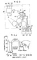
- the offset printer comprises an impression cylinder 30, a blanket cylinder 31, a plate cylinder 33, an inking device including a form roller 34, inking rollers 36, an ink ductor 37, an ink fountain roller 38 and an ink fountain 39, and a damping water device including a damping water tank 41, a water fountain roller 42, a roller 43 and a form damping roller 44.
- the metal roller 35 or 40 of the inking rollers 36 measures the film thickness of the ink and the dampening water
- the metal roller may be replaced with other ink roller formed of material which is difficult to absorb infrared rays.
- a sampling roller may be provided in the inking rollers 36 to measure the film thickness of the ink and the dampening water.
- Figs. 1 and 5 The automatic control apparatus is decribed with reference to Figs. 1 and 5.
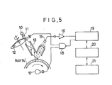
- numeral 10 denotes an infrared emitting element, 11 a lens, 12 an interference filter, 13 a light guide pipe, 14 the mixture liquid layer of the ink and the dampening water existing on the metal roller 35, 15 a photoelectric element (a measuring device or a detector) disposed in the vicinity of the metal roller 35, 16 an amplifier, 18 a synchronizer, 19 an A/D converter, 20 a computer and 21 a plotter.
- numerals 23 and 24 denote D/A converters, 25 a motor for driving the ink fountain roller and 26 a motor for driving the water fountain roller.
- the infrared rays are used to detect the film thickness of the ink and the dampening water.
- the material absorbs light having a particular wavelength and remaining light is accordinglyl observed as a color of the material.
- the absorption of light having the particular wavelength is effected to not only a range of visible rays but also a range from ultraviolet rays to infrared rays. Since an infrared absoption spectrum in the wavelength range of 2.5 ⁇ m to 10 ⁇ m has clear correlation of the absoprion characteristic and the molecular structure, it is most suitable obtain knowledge concerning compound structure.
- Curves 1 and of Fig. 2 show infrared absorption spectra of the ink and the dampening water in the wavelength range of 2.5 ⁇ m to 10 ⁇ m measured by an infrared spectrophotometer.
- absorption zones for the ink in the above spectrum exist in three wavelengths of 3.40 um (see 3 of Fig. 2), 5.40 ⁇ m (see 4 and 6.85 ⁇ m (see5.
- the facts are due to the molecular structure of vehicle in the ink and is not related to a color of pigment. That is, an offset ink generally used exhibits the almost same absorption characteristic and measurement can be performed in the same absorption zone independently of types of ink.
- Absorption zones for the water exist in three wavelengths of 2.96 ⁇ m (see6 of Fig.
- the rate is related to thickness and density of a layer of a material.
- An index representing the rate of the absorption generally uses transmittance represented by a ratio of intensity Io of incident light and intensity I of transmitted light and the transmittance is proportional to the thickness and the density of the layer.
- Fig. 5 shows a configuration of a detection device of film thickness of the oil material and the water for use in an embodiment of the present invention. While the detection device is a percentage meter of water content in film thickness of ink described in Japanese Patent Application No. 58-124418, since the infrared spectrum characteritic of printing ink of the embodiment and varnish of a second embodiment is almost identical, the detection device can be applied to both the embodiments.
- the automatic control apparatus for ink and dampening water shown in Figs. 1 and 5 utilizes the above principle.
- Infrared rays emitted from the infrared emitting element 10 forming a light source are condensed by the lens 11 and then pass through the interference filter 12.
- the interference filter 12 is provided with three types filters of a filter for infrared rays absorbed into the ink, a filter for infrared rays absorbed into the dampening water and a filter for reference rays which are not absorbed into the ink and the dampening water.
- the infrared rays passing through the reference filter are used to correct a measured value in absorption of the infrared rays on a basic material of the roller and to correct the measured value in accordance with variation of a measurement distance between the light guide pipe 13 and the roller 35 due to mechanical vibration.
- the three types of filters are mounted in a chopper wheel so that infrared rays alternately illuminate the roller 35 by rotation of the chopper wheel.
- Light passig through the interference filter illuminates emulsified ink 14 (that is, a mixture liquid layer of ink and dampening water) on the roller 35 through the light guide pipe 13. A portion of this light is absorbed into the emulsified ink while remaining light is reflected and condensed to the photoelectric element 15.
- the remaining light is converted to an electric signal by the photoelectric element 15 and the signal amplified by the amplifier 16 is supplied to the A/D converter 19.
- the rotational number of the roller 35 and the rotational number of the interference filter 12 are detected and the detected signals are supplied to the A/D converter 19 through the synchronizer 18.
- the digitized signals of the A/D converter 19 are supplied to the computer 20 together with other necessary signals to calculate the film thickness of the ink and the percentage of water content, which are supplied to the plotter 20.
- control signals are applied from the computer 20 through the D/A converters 23 and 24 to the motor 25 for driving the ink fountain roller and the motor 26 for driving the water fountain roller to control the rotational numbers of the motors 25 and 26.
- the varnish coating device comprises a roller group composed of a rubber blanket cylinder 137, an intermediate cylinder 138, an impression cylinder 139, a delivery shaft 140, a varnish saucer 133, a fountain roll 134, an intermediate roller 135 and a form roller 136 and a varnish feeding unit composed of a varnish tank 130, a mixture tank 131, a water tank 132 and pumps 128, 129 and 127.
- a detection device 22 for varnish and water which is the same as the device shown in Fig.
- Fig. 4 shows infrared absorption spectra of varnish and water in a wavelength range of 2.5 ⁇ m to 10 ⁇ m measured by an infrared spectrophotometer.
- varnish used in a printer exhibits similar characteristic independently of types of varnish and hence measurement can be made in the absorption zones having the same wavelengths.
- Absorption zones of water exist in three wavelengths of 2.96 ⁇ m, 4.80 um and 6.10 ⁇ m. An actual measurement uses the wavelengths most strongly absorbed, of these absorption wavelengths, that is, the wavelength of 3.40 ⁇ m for the ink and the wavelength of 2.96 ⁇ m for the water.
- the index representing the rate of the absorpted infrared rays into material generally uses transmittance as described above, and the transmittance is proportional to the thickness and the density of the layer.
- the transmittance is proportional to the thickness and the density of the layer.
- the detection device of film thickness of varnish and water used in the present embodiment uses the film thickness detection device shown in Fig. 5 in the same manner as in the first embodiment. Accordingly, operation and processing of electric signals of the detection device are the same as those of the first embodiment and description thereof is omitted.
- numeral 14' denotes a mixture liquid layer of varnish and water.
- the measuring roller used in the present invention is not limited to the metal roller and may be other roller having small absorption for infrared rays. Further, measuring and control can be effected if the sampling roller is rounted in the roller group.
- the varnish and the water on the roller in the printer are detected in non-contact manner to automatically control the rotational number of the feeding roller and the ratio of the varnish and the water, and the stable film thickness of the varnish an be obtained independently of environmental conditions.
Landscapes
- Inking, Control Or Cleaning Of Printing Machines (AREA)
Applications Claiming Priority (4)
| Application Number | Priority Date | Filing Date | Title |
|---|---|---|---|
| JP59271053A JPH0798396B2 (ja) | 1984-12-24 | 1984-12-24 | オフセット印刷機におけるインキと湿し水との量的バランスの自動制御方法 |
| JP271053/84 | 1984-12-24 | ||
| JP118927/85 | 1985-06-03 | ||
| JP60118927A JPS61277455A (ja) | 1985-06-03 | 1985-06-03 | 印刷機におけるニスコ−ト膜厚の自動制御システム |
Publications (3)
| Publication Number | Publication Date |
|---|---|
| EP0186620A2 true EP0186620A2 (fr) | 1986-07-02 |
| EP0186620A3 EP0186620A3 (en) | 1988-06-08 |
| EP0186620B1 EP0186620B1 (fr) | 1992-04-15 |
Family
ID=26456759
Family Applications (1)
| Application Number | Title | Priority Date | Filing Date |
|---|---|---|---|
| EP85730173A Expired - Lifetime EP0186620B1 (fr) | 1984-12-24 | 1985-12-23 | Méthode de commande de l'épaisseur du film d'amalgame liquide de corps gras et d'eau dans les machines à imprimer |
Country Status (2)
| Country | Link |
|---|---|
| EP (1) | EP0186620B1 (fr) |
| DE (1) | DE3585875D1 (fr) |
Cited By (8)
| Publication number | Priority date | Publication date | Assignee | Title |
|---|---|---|---|---|
| DE3611645A1 (de) * | 1986-04-07 | 1987-10-08 | Grapho Metronic Gmbh & Co | Verfahren und vorrichtung zur regelung der farb- und feuchtmittelanteile einer emulsionsschicht auf der druckplatte einer offset-druckmaschine |
| EP0482309A1 (fr) * | 1990-10-22 | 1992-04-29 | JAGENBERG Aktiengesellschaft | Dispositif pour revêtir les deux faces d'un matériau en bande |
| US5289774A (en) * | 1991-08-14 | 1994-03-01 | Baldwin-Gegenheimer Gmbh | Sheet-cleaning apparatus |
| US5313886A (en) * | 1992-06-06 | 1994-05-24 | Heidelberger Druckmaschinen Ag | Electronic method of positioning a register mark sensor of a sheet printing machine |
| GB2273907A (en) * | 1992-12-30 | 1994-07-06 | Heidelberger Druckmasch Ag | Process for supplying damping solution |
| EP1391319A3 (fr) * | 2002-08-22 | 2004-08-18 | Fuji Photo Film Co., Ltd. | Procédé d'impression lithographique et presse lithographique |
| CN108303241A (zh) * | 2017-12-28 | 2018-07-20 | 西安理工大学 | 一种模块化油膜阻尼测试装置与方法 |
| EP3517299A4 (fr) * | 2016-09-26 | 2020-05-27 | Komori Corporation | Procédé de mesure d'épaisseur de film de vernis d'un article imprimé et dispositif de mesure d'épaisseur de film de vernis |
Families Citing this family (1)
| Publication number | Priority date | Publication date | Assignee | Title |
|---|---|---|---|---|
| DE19536318B4 (de) * | 1995-09-29 | 2004-05-06 | Pts Jena Gmbh | Vorrichtung zur gewichtsabhängigen Gebührenberechnung für Abfallsammelbehälter |
Family Cites Families (6)
| Publication number | Priority date | Publication date | Assignee | Title |
|---|---|---|---|---|
| DE2214721B1 (de) * | 1972-03-25 | 1973-06-14 | Heidelberger Druckmaschinen Ag, 6900 Heidelberg | Verfahren und vorrichtung zum selbsttaetigen ausregeln von schwankungen der farb- und feuchtfluessigkeitsfuehrung an offsetmaschinen |
| DE2736663C3 (de) * | 1977-08-13 | 1985-05-15 | Heidelberger Druckmaschinen Ag, 6900 Heidelberg | Vorrichtung zur Ermittlung des Feucht- und Farbgleichgewichts bei Offsetdruckwerken |
| US4149802A (en) * | 1978-01-09 | 1979-04-17 | Roland Offsetmaschinenfabrik Faber & Schleicher Ag | Device for measuring ink film thickness |
| GB2016678B (en) * | 1978-03-10 | 1982-09-15 | Asahi Dow Ltd | Infrared multilayer film thickness measuring method and apparatus |
| US4306152A (en) * | 1979-07-23 | 1981-12-15 | Anarad, Inc. | Optical fluid analyzer |
| GB2127541B (en) * | 1982-09-27 | 1986-08-20 | Imp Group Plc | Monitoring sheet material |
-
1985
- 1985-12-23 DE DE8585730173T patent/DE3585875D1/de not_active Expired - Lifetime
- 1985-12-23 EP EP85730173A patent/EP0186620B1/fr not_active Expired - Lifetime
Cited By (12)
| Publication number | Priority date | Publication date | Assignee | Title |
|---|---|---|---|---|
| DE3611645A1 (de) * | 1986-04-07 | 1987-10-08 | Grapho Metronic Gmbh & Co | Verfahren und vorrichtung zur regelung der farb- und feuchtmittelanteile einer emulsionsschicht auf der druckplatte einer offset-druckmaschine |
| EP0482309A1 (fr) * | 1990-10-22 | 1992-04-29 | JAGENBERG Aktiengesellschaft | Dispositif pour revêtir les deux faces d'un matériau en bande |
| US5289774A (en) * | 1991-08-14 | 1994-03-01 | Baldwin-Gegenheimer Gmbh | Sheet-cleaning apparatus |
| US5313886A (en) * | 1992-06-06 | 1994-05-24 | Heidelberger Druckmaschinen Ag | Electronic method of positioning a register mark sensor of a sheet printing machine |
| GB2273907A (en) * | 1992-12-30 | 1994-07-06 | Heidelberger Druckmasch Ag | Process for supplying damping solution |
| GB2273907B (en) * | 1992-12-30 | 1996-03-20 | Heidelberger Druckmasch Ag | Process for the supply of damping solution |
| EP1391319A3 (fr) * | 2002-08-22 | 2004-08-18 | Fuji Photo Film Co., Ltd. | Procédé d'impression lithographique et presse lithographique |
| US6834590B2 (en) * | 2002-08-22 | 2004-12-28 | Fuji Photo Film Co., Ltd. | Lithographic printing method and printing press |
| EP3517299A4 (fr) * | 2016-09-26 | 2020-05-27 | Komori Corporation | Procédé de mesure d'épaisseur de film de vernis d'un article imprimé et dispositif de mesure d'épaisseur de film de vernis |
| US11358386B2 (en) | 2016-09-26 | 2022-06-14 | Komori Corporation | Method for measuring varnish film thickness of printed article and varnish film thickness measurement device |
| CN108303241A (zh) * | 2017-12-28 | 2018-07-20 | 西安理工大学 | 一种模块化油膜阻尼测试装置与方法 |
| CN108303241B (zh) * | 2017-12-28 | 2019-09-27 | 西安理工大学 | 一种模块化油膜阻尼测试装置与方法 |
Also Published As
| Publication number | Publication date |
|---|---|
| DE3585875D1 (de) | 1992-05-21 |
| EP0186620A3 (en) | 1988-06-08 |
| EP0186620B1 (fr) | 1992-04-15 |
Similar Documents
| Publication | Publication Date | Title |
|---|---|---|
| US4677298A (en) | Method of monitoring ink-water balance on a lithographic printing press | |
| US6065400A (en) | Method for monitoring registration of images printed by a printer | |
| CN102123867B (zh) | 用于对印刷机进行油墨调节的方法 | |
| US20030110963A1 (en) | Ink and dampening solution determination in offset printing | |
| EP0186620A2 (fr) | Méthode de commande de l'épaisseur du film d'amalgame liquide de corps gras et d'eau dans les machines à imprimer | |
| CN102123868B (zh) | 用于检测至少一个在印刷机中确定的测量值的可信度的方法 | |
| JPH0360312B2 (fr) | ||
| US4681455A (en) | Method of determining the area coverage of a printed original or printing plate for printing presses | |
| US20080201110A1 (en) | Ink Splitting Correction Method | |
| US3960451A (en) | Dampening system on an offset printing press with a device for regulating the amount of water on the plate | |
| FI115205B (fi) | Menetelmä ja laite painojäljen on-line valvomiseksi | |
| US5713286A (en) | Method for regulating dampening agent | |
| JPS61148061A (ja) | オフセツト印刷機におけるインキと湿し水の自動制御方法 | |
| CN101670703B (zh) | 强度优化的控制标记测量 | |
| US5162865A (en) | Method and device for positioning a sensor device | |
| US7444935B2 (en) | Method for correction of variations in the amount of ink applied in a printing process | |
| JP4638685B2 (ja) | オフセット印刷機による印刷の際に湿し水を調量する方法 | |
| EP0864931A1 (fr) | Réflectomètre et procédé de surveillance de la densité de mtériau imprimé | |
| US4207003A (en) | Sensing device for ink film thickness in printing presses | |
| US5774226A (en) | Method of scanning register marks produced in multicolor printing | |
| GB2235901A (en) | Print control strip examination device | |
| JP3269831B2 (ja) | インキ顔料濃度制御方法及び装置 | |
| KR100297786B1 (ko) | 습식 인쇄기의 현상액 농도 측정장치 | |
| JP2002225231A (ja) | 絵柄色調監視装置および印刷色調制御装置 | |
| AU2001237144B2 (en) | Ink and dampening solution determination in offset printing |
Legal Events
| Date | Code | Title | Description |
|---|---|---|---|
| PUAI | Public reference made under article 153(3) epc to a published international application that has entered the european phase |
Free format text: ORIGINAL CODE: 0009012 |
|
| AK | Designated contracting states |
Kind code of ref document: A2 Designated state(s): DE FR GB IT SE |
|
| 17P | Request for examination filed |
Effective date: 19860702 |
|
| PUAL | Search report despatched |
Free format text: ORIGINAL CODE: 0009013 |
|
| AK | Designated contracting states |
Kind code of ref document: A3 Designated state(s): DE FR GB IT SE |
|
| 17Q | First examination report despatched |
Effective date: 19900209 |
|
| GRAA | (expected) grant |
Free format text: ORIGINAL CODE: 0009210 |
|
| ITF | It: translation for a ep patent filed | ||
| AK | Designated contracting states |
Kind code of ref document: B1 Designated state(s): DE FR GB IT SE |
|
| ET | Fr: translation filed | ||
| REF | Corresponds to: |
Ref document number: 3585875 Country of ref document: DE Date of ref document: 19920521 |
|
| PLBI | Opposition filed |
Free format text: ORIGINAL CODE: 0009260 |
|
| 26 | Opposition filed |
Opponent name: MAN ROLAND DRUCKMASCHINEN AG Effective date: 19921221 |
|
| PGFP | Annual fee paid to national office [announced via postgrant information from national office to epo] |
Ref country code: FR Payment date: 19931209 Year of fee payment: 9 |
|
| PGFP | Annual fee paid to national office [announced via postgrant information from national office to epo] |
Ref country code: GB Payment date: 19931214 Year of fee payment: 9 |
|
| PGFP | Annual fee paid to national office [announced via postgrant information from national office to epo] |
Ref country code: SE Payment date: 19931215 Year of fee payment: 9 |
|
| PGFP | Annual fee paid to national office [announced via postgrant information from national office to epo] |
Ref country code: DE Payment date: 19931227 Year of fee payment: 9 |
|
| RDAG | Patent revoked |
Free format text: ORIGINAL CODE: 0009271 |
|
| STAA | Information on the status of an ep patent application or granted ep patent |
Free format text: STATUS: PATENT REVOKED |
|
| 27W | Patent revoked |
Effective date: 19940529 |
|
| GBPR | Gb: patent revoked under art. 102 of the ep convention designating the uk as contracting state |
Free format text: 940529 |
|
| EUG | Se: european patent has lapsed |
Ref document number: 85730173.3 Effective date: 19941012 |