EP0186728A1 - Manchon de serrage pour tuyaux - Google Patents
Manchon de serrage pour tuyaux Download PDFInfo
- Publication number
- EP0186728A1 EP0186728A1 EP85108204A EP85108204A EP0186728A1 EP 0186728 A1 EP0186728 A1 EP 0186728A1 EP 85108204 A EP85108204 A EP 85108204A EP 85108204 A EP85108204 A EP 85108204A EP 0186728 A1 EP0186728 A1 EP 0186728A1
- Authority
- EP
- European Patent Office
- Prior art keywords
- clamping
- ring
- sheet metal
- clamping ring
- clamping sleeve
- Prior art date
- Legal status (The legal status is an assumption and is not a legal conclusion. Google has not performed a legal analysis and makes no representation as to the accuracy of the status listed.)
- Granted
Links
- 239000002184 metal Substances 0.000 claims abstract description 40
- 229910052751 metal Inorganic materials 0.000 claims abstract description 40
- 238000007789 sealing Methods 0.000 claims abstract description 29
- 239000011324 bead Substances 0.000 claims description 10
- 230000000284 resting effect Effects 0.000 claims 1
- 238000005452 bending Methods 0.000 description 5
- 229910001018 Cast iron Inorganic materials 0.000 description 1
- 239000010425 asbestos Substances 0.000 description 1
- 239000004568 cement Substances 0.000 description 1
- 238000010276 construction Methods 0.000 description 1
- 238000011835 investigation Methods 0.000 description 1
- 238000004519 manufacturing process Methods 0.000 description 1
- 239000000463 material Substances 0.000 description 1
- 229910052895 riebeckite Inorganic materials 0.000 description 1
- 239000010865 sewage Substances 0.000 description 1
- 210000002435 tendon Anatomy 0.000 description 1
- 230000003313 weakening effect Effects 0.000 description 1
Images

Classifications
-
- F—MECHANICAL ENGINEERING; LIGHTING; HEATING; WEAPONS; BLASTING
- F16—ENGINEERING ELEMENTS AND UNITS; GENERAL MEASURES FOR PRODUCING AND MAINTAINING EFFECTIVE FUNCTIONING OF MACHINES OR INSTALLATIONS; THERMAL INSULATION IN GENERAL
- F16L—PIPES; JOINTS OR FITTINGS FOR PIPES; SUPPORTS FOR PIPES, CABLES OR PROTECTIVE TUBING; MEANS FOR THERMAL INSULATION IN GENERAL
- F16L21/00—Joints with sleeve or socket
- F16L21/002—Sleeves or nipples for pipes of the same diameter; Reduction pieces
- F16L21/005—Sleeves or nipples for pipes of the same diameter; Reduction pieces made of elastic material, e.g. partly or completely surrounded by clamping devices
Definitions
- the invention relates to a clamping sleeve for pipes, consisting of a rubber-elastic sealing ring and a clamping ring surrounding the sealing ring in the form of a circularly bent sheet metal strip which is angled radially inwards
- Such a clamping sleeve is known from DE-GM 81 02 137.
- a special sheet metal part is welded to one end of the sheet metal strip which forms the clamping ring and extends to below the other end of the sheet metal strip.
- This sheet metal part is narrower than the sealing ring and has no radially angled edges.
- a clamping sleeve for pipes is known in which the clamping plates are arranged at a certain distance from the ends of the clamping ring, so that the end sections of the clamping ring can overlap immediately.
- the clamping ring has no radially angled edges.
- a clamping sleeve in which the tendons are formed by outwardly and rearwardly folded end portions of the tension band, which form a type of eyelet which extends transversely to the tension band and is penetrated transversely by the tension screws surrounds.
- the inwardly angled edges of the sheet metal strip only extend up to the eyes. The gap between The ends of the sheet metal strip are bridged by a loosely inserted, additional sheet metal part.
- Tensioning sleeves of the type described in the introduction are used to a large extent for connecting sewage pipes made of asbestos cement and cast iron. Because of the diameter tolerances of such pipes, the clamping sleeves have to be clamped to a considerable extent during assembly to compensate for the different diameters of adjacent pipes with the same nominal size. This can lead to deformations of the sealing ring, which result in lateral deflection of the sealing ring and thus lead to leaks. Although the radially inward angled edge of the clamping ring limits the sealing ring from breaking out, this does not completely prevent leaks. In the case of the clamping sleeve according to FR-PS 1 011 740, the additional sheet metal strip provided with a border can shift slightly or even get lost before or during assembly and therefore does not offer the required security.
- the invention has for its object to develop a clamping sleeve for pipes of the type described in such a way that the tightness of the clamping sleeve is improved and in particular a seal is guaranteed even at elevated pressures, without thereby complicating the structure and / or handling of the clamping sleeve .
- the gap bridging the gap between the clamping plates has radially inwardly angled edges formed by a sheet metal part formed over an end section of the tension ring projecting from the tensioning plates and which fit at least at the point of overlap with the end of the sheet metal strip between the angled edges of the sheet metal strip.
- the invention leads to a significant improvement in the sealing properties of the clamping sleeve and in particular its compressive strength. Since the sheet metal part itself is formed by an end section of the sheet metal strip projecting over one of the clamping plates, the clamping ring is particularly simple in design and at the same time particularly stable due to its one-piece construction. At last, no errors can be made when using it that result in leaks. However, special measures are required in the manufacture of such a clamping ring in order to reduce the width of the sheet metal strip at one end, so that there is no possibility of producing the sheet metal strip with the angled edges as an endless band, from which the sections required for producing the clamping rings are then produced be separated.
- a particularly preferred embodiment of the invention provides that the projecting end section of the sheet metal strip has at least one longitudinal slot extending to its end.
- a longitudinal slot allows the separated sections of the sheet metal strip to approach one another and thereby reduce the width of the sheet metal strip to such an extent that this end section with its radially inwardly angled edges can be inserted between the angled edges of the opposite end section of the clamping ring.
- a particular advantage of this measure is that by bending the sections separated by the longitudinal slot, a certain tilting of the nested end sections of the clamping ring against each other is possible, as can easily happen when the pipes to be connected have different diameters.
- a longitudinal slot is arranged in the middle of the sheet metal strip in the clamping sleeve according to the invention, the bending of the sections of the sheet metal strip separated by the longitudinal slot is facilitated and, in particular, is possible without risk of deformation of the sheet metal strip if the longitudinal slot opens into a transverse slot at its inner end the ends of which are only narrow strips of material remain, which do not offer great resistance to bending the sections. It is therefore expedient if the transverse slot, which is preferably arranged in the area of the clamping plate, extends to close to the outer edges of the sheet metal strip. Optimal conditions result when the length of the transverse slot is approximately 75% of the width of the sheet metal strip. Furthermore, it can be expedient if the longitudinal slot widens outwards.
- two longitudinal slots are arranged near each edge of the clamping ring.
- the relatively narrow edge strips formed in this way can in turn easily be bent far enough inward to fit between the edges at the other end of the sheet metal strip. Because of their angular profile, they themselves have a very high degree of rigidity.
- the section of the clamping ring remaining between the longitudinal slots is normally only exposed for a short distance near its root, so that it can withstand relatively large radial forces without further notice. Nevertheless, it may be expedient to stiffen the section of the tension ring lying between the longitudinal slots by at least one bead extending in the circumferential direction of the tension ring. This gives this section a high level of dimensional stability, which is particularly important if the clamping sleeve is not yet mounted on pipes to be connected, but is exposed when the clamping ring is not yet closed and is then easily exposed to the risk of bending.
- Two beads parallel to the slots are advantageously arranged. Furthermore, it is expedient if the beads are designed to run flat towards the end of the section, so that they do not hinder sliding over the clamped sealing ring in the circumferential direction when the tensioning band is closed.
- 1 and 2 consists of a rubber-elastic sealing ring 1 and a sealing ring surrounding the sealing ring 2 in the form of a circularly bent sheet metal strip, on the outside of which two sheet metal parts 3, 4 are fastened, the facing ends of which are angled and with each other Form spaced opposing, parallel clamping plates 5.
- These clamping plates are penetrated by a central clamping screw 6, which is supported on the respective outside of the clamping plate 5 with its head 7 via an intermediate piece 8 and with its other end via an intermediate piece 9 designed as a nut.
- the ends of the stiff sheet metal parts 3, 4 placed on the clamping ring are angled again after the sections forming the clamping plates 5, in the area of the middle and then twice, so that the clamping plates 5 in the area of the middle of the tab 11 protrude, which overlap the ends of the intermediate pieces 8, 9 and in this way form stops for the intermediate pieces.
- the sections located next to the tabs 11 are angled in a U-shape such that the legs 12 of these sections are arranged laterally next to the intermediate pieces 8, 9 and form lateral stops for these intermediate pieces.
- so-called pressure joint connections 14 serve to connect the sheet metal parts 3, 4 to the clamping ring 2.
- the one sheet metal part 3 is attached directly to the end of the clamping ring 2, while an end section 15 of the clamping ring projects beyond the other sheet metal part 4, which extends below the other end of the clamping ring 2 and thus forms a bridge, which the Clamping ring forms a complete circle.
- the edges 16 of the clamping ring 2 are angled inwards over their entire length, that is also in the region of the end section 15. The width of the end section 15 at its free end is reduced so much that the end section with the angled edges 17 between the angled edges 16 fits at the other end of the clamping ring 2.
- the end section 15 has a longitudinal slot 18 which widens towards its open end and extends from the free end of the end section to a transverse slot 19 which is located at the point where the clamping plate 5 of the adjacent sheet metal part 4 is located extends close to the outer edges of the tension band 2, so that only narrow connection points 20 remain at the ends of the transverse slot 9, which bend the sections 21 of the tension ring 2 separated by the longitudinal slot 18 in the tangential plane defined by these sections, i.e. in the direction of arrows 22 in Fig. 3, allow.
- the weakening of the end section 15 of the clamping ring 2 through the slots 18, 19 is completely harmless because the sections 21 of the clamping ring delimited by these slots nevertheless have a high degree of flexural rigidity and are properly held and guided.
- the bending stiffness results from the angled edges 17, while the position fixation is ensured on the one hand by the connection to the main part of the clamping ring 2 at the ends of the transverse slot 19 and on the other hand by the system both on the inside of the clamping ring 2 and on its angled edges 16 .
- the sections 21 do not have to transmit any clamping forces acting in the circumferential direction of the clamping sleeve, but should only prevent radial and axial deflection of the sealing ring 1 in the area between the two clamping plates 5. This task is performed perfectly by the sections 21, so that the sealing ring 1 is now properly pressed against the pipes over its entire circumference and also clamped in the axial direction and, even under strong internal pressure, a perfect seal of the pipes connected to one another by means of such a clamping sleeve is ensured.
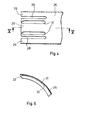
- the end section 25 of the clamping ring has two longitudinal slots 28 arranged near the lateral edges, through which the end section 25 is divided into two edge sections 29 and a central section 30.
- the edge sections 29 can be bent far enough inwards to be between the angled edges at the other end of the strap. At the same time, these sections 29 have high inherent rigidity because of their angular profile.
- the middle section 30 is stiffened by two beads 31, which are arranged close to the longitudinal slots 28 parallel to these. These beads 31 run flat at their ends 32, so they pass smoothly into the surface of the tensioning strap. This avoids sharp edges that could prevent a relative movement of the tensioning strap with respect to the pressed sealing ring, especially when tightening the tensioning strap. It can be seen that here too a structure is created which allows the end section 25 of the tensioning band to be inserted between the angled edges at the other end, without additional structural measures having to be taken to reduce the width of this end section 25, but in which the sections separated by the slots have a very high rigidity, so that they are not exposed to undue deformations.
- the invention is not limited to the exemplary embodiments shown. So there would be the possibility of leaving the end section 15 of the clamping ring unslotted and in another way giving it a reduced width so that it fits between the angled edges 16 at the other end of the clamping ring.
- the invention is also independent of the number of clamping screws acting on the clamping plates. It can be used in particular in those clamping sleeves where two such clamping screws are arranged parallel to each other and the clamping plates are divided in the area between the clamping screws, so that the clamping sleeve can better nestle on pipes of different diameters. Particularly with such clamping sleeves, considerable deformations of the clamping ring can occur, which remain without disadvantage for a perfect pressing of the sealing ring by the invention.
- the illustrated embodiments are currently considered to be the optimal realization of the inventive concept both in terms of their manufacturability and in terms of their function.
Landscapes
- Engineering & Computer Science (AREA)
- General Engineering & Computer Science (AREA)
- Mechanical Engineering (AREA)
- Flanged Joints, Insulating Joints, And Other Joints (AREA)
Priority Applications (3)
| Application Number | Priority Date | Filing Date | Title |
|---|---|---|---|
| AT85108204T ATE41049T1 (de) | 1984-12-15 | 1985-07-03 | Spannmuffe fuer rohre. |
| FI852918A FI80141C (fi) | 1984-12-15 | 1985-07-26 | Faestmuff foer roer. |
| CA000495259A CA1286092C (fr) | 1984-12-15 | 1985-11-13 | Manchon de bridage pour tuyauterie |
Applications Claiming Priority (2)
| Application Number | Priority Date | Filing Date | Title |
|---|---|---|---|
| DE3445807 | 1984-12-15 | ||
| DE19843445807 DE3445807A1 (de) | 1984-12-15 | 1984-12-15 | Spannmuffe fuer rohre |
Publications (2)
| Publication Number | Publication Date |
|---|---|
| EP0186728A1 true EP0186728A1 (fr) | 1986-07-09 |
| EP0186728B1 EP0186728B1 (fr) | 1989-03-01 |
Family
ID=6252870
Family Applications (1)
| Application Number | Title | Priority Date | Filing Date |
|---|---|---|---|
| EP85108204A Expired EP0186728B1 (fr) | 1984-12-15 | 1985-07-03 | Manchon de serrage pour tuyaux |
Country Status (3)
| Country | Link |
|---|---|
| US (1) | US4795199A (fr) |
| EP (1) | EP0186728B1 (fr) |
| DE (2) | DE3445807A1 (fr) |
Cited By (10)
| Publication number | Priority date | Publication date | Assignee | Title |
|---|---|---|---|---|
| EP0351019A1 (fr) * | 1988-07-14 | 1990-01-17 | Stona Holding B.V. | Manchon de réparation et ses moyens de fermeture |
| GB2239298A (en) * | 1989-12-21 | 1991-06-26 | Rasmussen Gmbh | Wide-band clip for connecting pipes and process for the production thereof |
| EP0447955A1 (fr) * | 1990-03-20 | 1991-09-25 | Straub Federnfabrik Ag | Raccord pour tuyau |
| US5203594A (en) * | 1990-06-18 | 1993-04-20 | Straub Federnfabrik | Pipe coupling |
| US5280969A (en) * | 1990-06-18 | 1994-01-25 | Straub Federnfabrik Ag | Pipe coupling |
| EP0779463A3 (fr) * | 1995-12-12 | 1997-07-09 | Mage AG | Manchon de serrage pour tuyaux |
| US5961161A (en) * | 1998-03-13 | 1999-10-05 | Mage Ag | Pipe connector clamp |
| DE10122647C1 (de) * | 2001-05-10 | 2002-04-18 | Rasmussen Gmbh | Rohrschelle, insbesondere Rohrkupplung |
| DE19727035C2 (de) * | 1997-06-25 | 2002-06-20 | Klein Umformtechnik Gmbh | Spannmuffe zur axialen Verbindung von zwei stirnseitig aneinanderstoßenden runden Rohrkörpern |
| WO2016142659A1 (fr) * | 2015-03-10 | 2016-09-15 | Taylor Kerr (Couplings) Limited | Raccord de tuyauterie |
Families Citing this family (11)
| Publication number | Priority date | Publication date | Assignee | Title |
|---|---|---|---|---|
| DE3710852C1 (de) * | 1987-04-01 | 1988-03-10 | Rasmussen Gmbh | Rohrkupplung |
| NZ238986A (en) * | 1990-07-27 | 1997-01-29 | Taylor Kerr Couplings Ltd | Fliud-tight pipe coupling with slots in sealing sleeve that receive teeth of gripping ring |
| GB9611410D0 (en) | 1996-05-31 | 1996-08-07 | Taylor Kerr Couplings Ltd | Pipe coupling |
| US5870865A (en) * | 1997-06-26 | 1999-02-16 | Everdry Marketing & Management, Inc. | Method for repairing a drainage system |
| DE19907776C1 (de) * | 1999-02-24 | 2000-11-23 | Rasmussen Gmbh | Steckkupplung zum axialen Verbinden zweier Rohre |
| US6584654B1 (en) | 2002-04-18 | 2003-07-01 | Epicor Industries, Inc. | T-bolt hose clamp |
| GB2389395B (en) | 2002-06-07 | 2006-02-15 | Taylor Kerr | Pipe coupling |
| US6805359B2 (en) * | 2002-10-25 | 2004-10-19 | Press-Seal Gasket Corporation | Expansion ring assembly |
| US20050082831A1 (en) * | 2003-10-15 | 2005-04-21 | Borland Robin N. | Conduit coupling |
| DE102005017368A1 (de) * | 2005-03-08 | 2006-09-21 | Metu Meinig Aktiengesellschaft | Offener Spannring mit Schraubenschloss |
| CN103062563A (zh) * | 2012-11-08 | 2013-04-24 | 广西梧州五一塑料制品有限公司 | 可拆分塑料管接头 |
Citations (2)
| Publication number | Priority date | Publication date | Assignee | Title |
|---|---|---|---|---|
| DE2919939A1 (de) * | 1979-05-17 | 1980-11-20 | Rasmussen Gmbh | Vorrichtung zum festspannen eines schlauches auf einem rohrfoermigen element |
| EP0057373A1 (fr) * | 1981-01-29 | 1982-08-11 | Mage Ag | Manchon de serrage pour tuyaux |
Family Cites Families (18)
| Publication number | Priority date | Publication date | Assignee | Title |
|---|---|---|---|---|
| CA706777A (en) * | 1965-03-30 | F. Corriston Winfield | Band clamp | |
| US3104898A (en) * | 1963-09-24 | Tube couplers | ||
| FR703105A (fr) * | 1930-10-02 | 1931-04-25 | Stac Midi | Joint à corps indépendant pour canalisation de fluides avec ou sans pression |
| US2417741A (en) * | 1943-06-24 | 1947-03-18 | Hanlon Waters Division Of Gene | Split packing ring coupling |
| FR1011740A (fr) * | 1949-03-11 | 1952-06-26 | Beon Luyrieu Ain Sa | Joint de tuyaux |
| US2998269A (en) * | 1958-10-30 | 1961-08-29 | Amercoat Corp | Plastic pipe coupling having an adhesive coated wedge ring |
| US3142881A (en) * | 1962-06-06 | 1964-08-04 | Alva J Johnston | Hose clamp |
| US3572773A (en) * | 1966-09-15 | 1971-03-30 | Owens Illinois Inc | Glass pipe joint |
| US3419291A (en) * | 1967-01-30 | 1968-12-31 | Corning Glass Works | Pipe coupling |
| BE792921A (fr) * | 1971-12-17 | 1973-06-18 | Corning Glass Works | Raccord pour assembler des tubes |
| US3834744A (en) * | 1972-06-19 | 1974-09-10 | Garlock Inc | Pipe coupling |
| CH553365A (de) * | 1972-12-13 | 1974-08-30 | Von Roll Ag | Rohrverbindung. |
| DE8102137U1 (de) * | 1981-01-29 | 1982-08-19 | Mage Ag, Courtaman | Spannmuffe fuer rohre |
| US4492393A (en) * | 1981-08-31 | 1985-01-08 | Parker Hannifin Corporation | Pipe restraint device |
| CH653113A5 (de) * | 1981-11-05 | 1985-12-13 | Immanuel Straub | Rohrkupplung sowie verwendung derselben. |
| US4521940A (en) * | 1982-02-23 | 1985-06-11 | Hans Oetiker | Hose clamp |
| DE3339169C2 (de) * | 1983-10-28 | 1986-05-15 | Rasmussen Gmbh, 6457 Maintal | Steckkupplung zum Verbinden der Enden zweier Rohre |
| DE3404739C1 (de) * | 1984-02-10 | 1985-07-25 | Rasmussen Gmbh, 6457 Maintal | Steckkupplung zum Verbinden der Enden zweier Rohre |
-
1984
- 1984-12-15 DE DE19843445807 patent/DE3445807A1/de not_active Ceased
-
1985
- 1985-07-03 EP EP85108204A patent/EP0186728B1/fr not_active Expired
- 1985-07-03 DE DE8585108204T patent/DE3568480D1/de not_active Expired
- 1985-10-04 US US06/784,166 patent/US4795199A/en not_active Expired - Lifetime
Patent Citations (2)
| Publication number | Priority date | Publication date | Assignee | Title |
|---|---|---|---|---|
| DE2919939A1 (de) * | 1979-05-17 | 1980-11-20 | Rasmussen Gmbh | Vorrichtung zum festspannen eines schlauches auf einem rohrfoermigen element |
| EP0057373A1 (fr) * | 1981-01-29 | 1982-08-11 | Mage Ag | Manchon de serrage pour tuyaux |
Cited By (14)
| Publication number | Priority date | Publication date | Assignee | Title |
|---|---|---|---|---|
| EP0351019A1 (fr) * | 1988-07-14 | 1990-01-17 | Stona Holding B.V. | Manchon de réparation et ses moyens de fermeture |
| GB2239298B (en) * | 1989-12-21 | 1993-06-02 | Rasmussen Gmbh | Wide-band clip and process for the production thereof |
| GB2239298A (en) * | 1989-12-21 | 1991-06-26 | Rasmussen Gmbh | Wide-band clip for connecting pipes and process for the production thereof |
| EP0447955A1 (fr) * | 1990-03-20 | 1991-09-25 | Straub Federnfabrik Ag | Raccord pour tuyau |
| US5137305A (en) * | 1990-03-20 | 1992-08-11 | Straub Federnfabrik Ag | Pipe coupling |
| AU627987B2 (en) * | 1990-03-20 | 1992-09-03 | Straub Federnfabrik Ag | Pipe coupling |
| CH681318A5 (fr) * | 1990-03-20 | 1993-02-26 | Straub Federnfabrik | |
| US5203594A (en) * | 1990-06-18 | 1993-04-20 | Straub Federnfabrik | Pipe coupling |
| US5280969A (en) * | 1990-06-18 | 1994-01-25 | Straub Federnfabrik Ag | Pipe coupling |
| EP0779463A3 (fr) * | 1995-12-12 | 1997-07-09 | Mage AG | Manchon de serrage pour tuyaux |
| DE19727035C2 (de) * | 1997-06-25 | 2002-06-20 | Klein Umformtechnik Gmbh | Spannmuffe zur axialen Verbindung von zwei stirnseitig aneinanderstoßenden runden Rohrkörpern |
| US5961161A (en) * | 1998-03-13 | 1999-10-05 | Mage Ag | Pipe connector clamp |
| DE10122647C1 (de) * | 2001-05-10 | 2002-04-18 | Rasmussen Gmbh | Rohrschelle, insbesondere Rohrkupplung |
| WO2016142659A1 (fr) * | 2015-03-10 | 2016-09-15 | Taylor Kerr (Couplings) Limited | Raccord de tuyauterie |
Also Published As
| Publication number | Publication date |
|---|---|
| DE3445807A1 (de) | 1986-06-26 |
| US4795199A (en) | 1989-01-03 |
| DE3568480D1 (en) | 1989-04-06 |
| EP0186728B1 (fr) | 1989-03-01 |
Similar Documents
| Publication | Publication Date | Title |
|---|---|---|
| EP0186728B1 (fr) | Manchon de serrage pour tuyaux | |
| DE3872974T2 (de) | Geschichteter splint oder verriegelungsklammer und kupplungen und verbindungen damit. | |
| EP0175856B1 (fr) | Collier de serrage avec vis tendeuse | |
| DE69614611T2 (de) | Rohrverbindung | |
| DE69209627T2 (de) | Schnellverbindungseinrichtung zur dichten Verbindung zweier Leitungen oder zweier starrer oder halbstarrer Rohre | |
| DE102007061288A1 (de) | Vorrichtung zum Verbinden von zwei Leitungen | |
| EP0140314A2 (fr) | Vanne à tiroir coulissant. | |
| DE3507151C2 (de) | Kupplungsglied für eine Schnellkupplung | |
| DE19705222C2 (de) | Anordnung zum Verbinden zweier rohrförmiger Elemente | |
| DE3613880C1 (de) | Dichtungsanordnung | |
| DE3521903A1 (de) | Offene klammer | |
| DE1963299C3 (de) | Anschluß für mindestens ein druckmittelbeaufschlagtes, ein glattes Ende aufweisendes rohrförmiges Element | |
| AT395643B (de) | Ohrlose klemmschelle | |
| DE69401399T2 (de) | Rohrschelle | |
| EP0057373B1 (fr) | Manchon de serrage pour tuyaux | |
| DE69423851T2 (de) | Ohrlose, stufenlose Rohrschellenstruktur | |
| DE2553058A1 (de) | Rohrkupplung | |
| AT393309B (de) | Vorrichtung zum verbinden von mit flanschen versehenen rohren | |
| EP0717204A1 (fr) | Goujon de sécurité, qui peut être inséré dans des trous passant dans des pièces jusqu'à une butée | |
| DE9217697U1 (de) | Klappenventil | |
| DE2263397A1 (de) | Kupplung | |
| DE8436762U1 (de) | Spannmuffe für Rohre | |
| DE3301229A1 (de) | Breitbandschelle zum abgedichteten verbinden von glattzylindrischen rohrenden, insbesondere von abwasserrohren mittels eines dichtungselements | |
| EP0379106B1 (fr) | Assemblage de connexion | |
| DE3127758C2 (de) | Vorrichtung zur Verbindung von mit Flanschen versehenen Kunststoffrohren |
Legal Events
| Date | Code | Title | Description |
|---|---|---|---|
| PUAI | Public reference made under article 153(3) epc to a published international application that has entered the european phase |
Free format text: ORIGINAL CODE: 0009012 |
|
| AK | Designated contracting states |
Kind code of ref document: A1 Designated state(s): AT BE CH DE FR GB IT LI NL SE |
|
| 17P | Request for examination filed |
Effective date: 19860621 |
|
| 17Q | First examination report despatched |
Effective date: 19871201 |
|
| GRAA | (expected) grant |
Free format text: ORIGINAL CODE: 0009210 |
|
| AK | Designated contracting states |
Kind code of ref document: B1 Designated state(s): AT BE CH DE FR GB IT LI NL SE |
|
| REF | Corresponds to: |
Ref document number: 41049 Country of ref document: AT Date of ref document: 19890315 Kind code of ref document: T |
|
| REF | Corresponds to: |
Ref document number: 3568480 Country of ref document: DE Date of ref document: 19890406 |
|
| ET | Fr: translation filed | ||
| GBT | Gb: translation of ep patent filed (gb section 77(6)(a)/1977) | ||
| ITF | It: translation for a ep patent filed | ||
| PLBE | No opposition filed within time limit |
Free format text: ORIGINAL CODE: 0009261 |
|
| STAA | Information on the status of an ep patent application or granted ep patent |
Free format text: STATUS: NO OPPOSITION FILED WITHIN TIME LIMIT |
|
| 26N | No opposition filed | ||
| PGFP | Annual fee paid to national office [announced via postgrant information from national office to epo] |
Ref country code: BE Payment date: 19910628 Year of fee payment: 7 |
|
| PGFP | Annual fee paid to national office [announced via postgrant information from national office to epo] |
Ref country code: NL Payment date: 19910731 Year of fee payment: 7 |
|
| PG25 | Lapsed in a contracting state [announced via postgrant information from national office to epo] |
Ref country code: BE Effective date: 19920731 |
|
| BERE | Be: lapsed |
Owner name: MAGE A.G. Effective date: 19920731 |
|
| PG25 | Lapsed in a contracting state [announced via postgrant information from national office to epo] |
Ref country code: NL Effective date: 19930201 |
|
| NLV4 | Nl: lapsed or anulled due to non-payment of the annual fee | ||
| ITTA | It: last paid annual fee | ||
| EAL | Se: european patent in force in sweden |
Ref document number: 85108204.0 |
|
| PGFP | Annual fee paid to national office [announced via postgrant information from national office to epo] |
Ref country code: FR Payment date: 20010626 Year of fee payment: 17 |
|
| REG | Reference to a national code |
Ref country code: GB Ref legal event code: IF02 |
|
| PGFP | Annual fee paid to national office [announced via postgrant information from national office to epo] |
Ref country code: GB Payment date: 20020625 Year of fee payment: 18 |
|
| PGFP | Annual fee paid to national office [announced via postgrant information from national office to epo] |
Ref country code: SE Payment date: 20020723 Year of fee payment: 18 |
|
| PGFP | Annual fee paid to national office [announced via postgrant information from national office to epo] |
Ref country code: CH Payment date: 20020724 Year of fee payment: 18 |
|
| PGFP | Annual fee paid to national office [announced via postgrant information from national office to epo] |
Ref country code: AT Payment date: 20020730 Year of fee payment: 18 |
|
| PG25 | Lapsed in a contracting state [announced via postgrant information from national office to epo] |
Ref country code: FR Free format text: LAPSE BECAUSE OF NON-PAYMENT OF DUE FEES Effective date: 20030331 |
|
| REG | Reference to a national code |
Ref country code: FR Ref legal event code: ST |
|
| PG25 | Lapsed in a contracting state [announced via postgrant information from national office to epo] |
Ref country code: GB Free format text: LAPSE BECAUSE OF NON-PAYMENT OF DUE FEES Effective date: 20030703 Ref country code: AT Free format text: LAPSE BECAUSE OF NON-PAYMENT OF DUE FEES Effective date: 20030703 |
|
| PG25 | Lapsed in a contracting state [announced via postgrant information from national office to epo] |
Ref country code: SE Free format text: LAPSE BECAUSE OF NON-PAYMENT OF DUE FEES Effective date: 20030704 |
|
| PGFP | Annual fee paid to national office [announced via postgrant information from national office to epo] |
Ref country code: DE Payment date: 20030730 Year of fee payment: 19 |
|
| PG25 | Lapsed in a contracting state [announced via postgrant information from national office to epo] |
Ref country code: LI Free format text: LAPSE BECAUSE OF NON-PAYMENT OF DUE FEES Effective date: 20030731 Ref country code: CH Free format text: LAPSE BECAUSE OF NON-PAYMENT OF DUE FEES Effective date: 20030731 |
|
| GBPC | Gb: european patent ceased through non-payment of renewal fee |
Effective date: 20030703 |
|
| EUG | Se: european patent has lapsed | ||
| REG | Reference to a national code |
Ref country code: CH Ref legal event code: PL |
|
| PG25 | Lapsed in a contracting state [announced via postgrant information from national office to epo] |
Ref country code: DE Free format text: LAPSE BECAUSE OF NON-PAYMENT OF DUE FEES Effective date: 20050201 |