EP0186733A2 - Dos d'âne respectant la dynamique du mouvement des véhicules sur des voies de circulation - Google Patents
Dos d'âne respectant la dynamique du mouvement des véhicules sur des voies de circulation Download PDFInfo
- Publication number
- EP0186733A2 EP0186733A2 EP85111723A EP85111723A EP0186733A2 EP 0186733 A2 EP0186733 A2 EP 0186733A2 EP 85111723 A EP85111723 A EP 85111723A EP 85111723 A EP85111723 A EP 85111723A EP 0186733 A2 EP0186733 A2 EP 0186733A2
- Authority
- EP
- European Patent Office
- Prior art keywords
- plates
- threshold
- ramp
- area
- driving surface
- Prior art date
- Legal status (The legal status is an assumption and is not a legal conclusion. Google has not performed a legal analysis and makes no representation as to the accuracy of the status listed.)
- Granted
Links
Images


Classifications
-
- E—FIXED CONSTRUCTIONS
- E01—CONSTRUCTION OF ROADS, RAILWAYS, OR BRIDGES
- E01F—ADDITIONAL WORK, SUCH AS EQUIPPING ROADS OR THE CONSTRUCTION OF PLATFORMS, HELICOPTER LANDING STAGES, SIGNS, SNOW FENCES, OR THE LIKE
- E01F1/00—Construction of station or like platforms or refuge islands or like islands in traffic areas, e.g. intersection or filling-station islands; Kerbs specially adapted for islands in traffic areas
- E01F1/005—Portable or movable traffic-area platforms or islands, e.g. portable loading islands, retractable platforms for traffic-directing officer
-
- E—FIXED CONSTRUCTIONS
- E01—CONSTRUCTION OF ROADS, RAILWAYS, OR BRIDGES
- E01C—CONSTRUCTION OF, OR SURFACES FOR, ROADS, SPORTS GROUNDS, OR THE LIKE; MACHINES OR AUXILIARY TOOLS FOR CONSTRUCTION OR REPAIR
- E01C5/00—Pavings made of prefabricated single units
- E01C5/005—Individual couplings or spacer elements for joining the prefabricated units
-
- E—FIXED CONSTRUCTIONS
- E01—CONSTRUCTION OF ROADS, RAILWAYS, OR BRIDGES
- E01F—ADDITIONAL WORK, SUCH AS EQUIPPING ROADS OR THE CONSTRUCTION OF PLATFORMS, HELICOPTER LANDING STAGES, SIGNS, SNOW FENCES, OR THE LIKE
- E01F1/00—Construction of station or like platforms or refuge islands or like islands in traffic areas, e.g. intersection or filling-station islands; Kerbs specially adapted for islands in traffic areas
-
- E—FIXED CONSTRUCTIONS
- E01—CONSTRUCTION OF ROADS, RAILWAYS, OR BRIDGES
- E01F—ADDITIONAL WORK, SUCH AS EQUIPPING ROADS OR THE CONSTRUCTION OF PLATFORMS, HELICOPTER LANDING STAGES, SIGNS, SNOW FENCES, OR THE LIKE
- E01F9/00—Arrangement of road signs or traffic signals; Arrangements for enforcing caution
- E01F9/50—Road surface markings; Kerbs or road edgings, specially adapted for alerting road users
- E01F9/529—Road surface markings; Kerbs or road edgings, specially adapted for alerting road users specially adapted for signalling by sound or vibrations, e.g. rumble strips; specially adapted for enforcing reduced speed, e.g. speed bumps
-
- Y—GENERAL TAGGING OF NEW TECHNOLOGICAL DEVELOPMENTS; GENERAL TAGGING OF CROSS-SECTIONAL TECHNOLOGIES SPANNING OVER SEVERAL SECTIONS OF THE IPC; TECHNICAL SUBJECTS COVERED BY FORMER USPC CROSS-REFERENCE ART COLLECTIONS [XRACs] AND DIGESTS
- Y02—TECHNOLOGIES OR APPLICATIONS FOR MITIGATION OR ADAPTATION AGAINST CLIMATE CHANGE
- Y02A—TECHNOLOGIES FOR ADAPTATION TO CLIMATE CHANGE
- Y02A30/00—Adapting or protecting infrastructure or their operation
- Y02A30/60—Planning or developing urban green infrastructure
Definitions
- the invention relates to a dynamic driving threshold for motor vehicle routes consisting of at least two essentially prismatic, flat and a flat undersurface ramp plates which are placed against each other on blunt abutment surfaces and are composed in one piece from a threshold area with constant height (threshold height) and a wedge area , which, starting from the threshold height, ends at a very acute angle and at a leading edge in the plane of the lower surface and, if necessary, also arranged between these ramp plates, also butt-fitted intermediate plates with a flat upper driving surface, the thickness of which corresponds to the threshold height.
- the vehicle lane In the area of such thresholds / ramp-ups, the vehicle lane is generally raised to pavement level by changing the surface and raising it, kept at the height reached for a certain length and then lowered again to the lane level.
- the driver is thus forced to be considerate and cautious (for example, a speed of 30 km / h) and at the same time he must pay attention to the particular road situation.
- the dynamic driving threshold / ramp serves primarily to calm traffic in residential areas and can be described as the most effective means of reducing the speed required in living areas. (According to federal statistics, most accidents in residential areas result from excessive speeds).
- Dynamic driving thresholds / ramp-ups are used at all relevant meeting / conflict points between motorized vehicle traffic and pedestrians, i.e. in front of schools, kindergartens, churches, hospitals etc., in front of pedestrian crossings and bicycle fords; it is also possible to integrate crossings / fords for pedestrians and cyclists into the threshold / ramp; Furthermore, dynamic driving thresholds / ramp-ups are used to protect intersection and junction areas that are prone to accidents, i.e. locks (at the entrance to the living areas) or as sidewalk crossings. They can also be used in the area of construction sites and can also be used for traffic islands, road dividers and road narrowing.
- the dynamic driving threshold / ramp with its deliberately applied braking effect also reduces the incentive to use the streets of the residential area to be protected as crawl paths and shortcuts for unwanted non-resident through traffic.
- the previously known driving dynamic threshold / ramp for motor vehicles is made of asphalt, but preferably made of concrete or concrete paving stones and therefore, due to the material, has no elasticity whatsoever. This results in shocks in particular in the wedge areas, that is to say in the ascending or descending slopes, which are transmitted to the motor vehicle passing over the thresholds / ramp and also have a noise effect on the surroundings. Sometimes even the driving stability of the motor vehicle is impaired in such a way that there is damage, for example demolition of the exhaust system of the vehicle. In addition, with conventional sleepers / ramp-ups made of non-elastic materials, the driving comfort of the driver is clearly and directly perceptibly reduced, which often causes an aggressive reaction in the driver and, of course, at least relativizes his understanding of traffic calming measures.
- this object is achieved by ramp plates made of an elastic material, in particular rubber and preferably recycled rubber, which each form a single threshold area and a wedge area in one piece, with a rigid reinforcing strip essentially parallel to the approach edge in the wedge area , in particular a steel profile, is embedded, which extends essentially over the entire width of the ramp plate and has a plurality of screw holes that allow for a punctual screw fastening and, if necessary, intermediate plates arranged between these ramp plates made of the same elastic material, but with a flat upper driving surface and one of the Threshold height corresponding thickness.
- an elastic material in particular rubber and preferably recycled rubber
- Such a dynamic driving threshold / ramp made of a force-reducing material reacts with an advantageous elasticity when it is rolled over, i.e. the impact energy of the vehicle traveling over it is largely absorbed without the desired speed reduction being lost. This also hardly affects driving stability and vehicle damage cases in the manner mentioned at the outset can be virtually ruled out.
- Another very important disadvantage of concrete block sleepers is that rescue vehicles such as fire engines and ambulances are exposed to considerable dangers at excessive speeds - both due to the abrupt loss of vehicle stability and also due to the narrow physical limits of driveability. The situation is different, however, in the case of the dynamic driving threshold / ramp-up according to the invention: here, a loss of driving stability which endangers the occupants of an emergency vehicle only occurs at very greatly increased speeds.
- the dynamic driving threshold / ramp according to the invention therefore not only dampens the forces transmitted by a vehicle driving over it, but also noticeably reduces the noise caused by the material being driven over. In addition to this - as mentioned above - there are no abrupt braking and starting operations.
- the rapid installation / assembly of the dynamic driving threshold / ramp-up should also be particularly emphasized.
- it can be installed and installed in just one day in the area of a two-lane street.
- the duration of the partial blockage of the road required is considerably shorter (construction time of a conventional paved threshold / ramp-up at least 8 to 10 days).
- it can be realized with a comparatively much lower financial and structural effort compared to the road conversions practiced to date.
- the threshold / ramp according to the invention is designed for driving on vehicles weighing 55 tons.
- An important advantage of the dynamic driving threshold / ramp according to the invention is the universal applicability, which allows the construction-related modular system to cover practically all occurring widths and lengths with standard parts.
- the threshold is described from the perspective of a driver, for whom the length of a threshold is given, for example, by the distance that he drives when crossing the threshold, the width of the threshold is the extent of the threshold transverse to the direction of movement of the vehicle.
- the dynamic driving threshold according to the invention is built up from the ramp plates mentioned, normally also using intermediate plates and optionally using other plates.
- a bauka is characteristic Most similar set of prefabricated panels from which sleepers of normal dimensions can be created by laying and assembling on site.
- the lower surfaces of the wedge plates and the intermediate plates are each preferably rectangles, preferably squares in the case of the intermediate plates.
- the ramp plates in particular can have any course of their approach edge, so that, for example, traffic islands delimited by curves can also be built up. Due to the installation system used, damaged individual panels can be replaced quickly and easily, since only screw fastenings have to be loosened and adjacent panels can remain in place.
- the driving surface of the wedge area merges tangentially into the flat driving surface of the threshold area.
- the approach angle can initially be selected to be smaller and only then, at a certain distance from the approach edge, can it be continuously increased.
- the length of the threshold area is advantageously ten to eighty percent, preferably fifty percent, of the length of the wedge area.
- the ramp plates are not exclusive ascending or descending slopes, rather they also encompass a threshold area with a level driving surface. This makes it possible to build a threshold exclusively from ramp plates without creating a ridge-like tip at which bumps can occur.
- the critical transition area between up and down Sloping and driving surface of the threshold in a single element, namely the ramp plate this avoids that different loads occur when driving over at the joints, which can lead to a separation of individual plates from each other.
- the angle of inclination of the wedge region is preferably between five degrees and fifteen degrees, preferably between seven degrees and eleven degrees.
- Such flat ascending and descending slopes can be easily and safely rolled over by motor vehicles even at impermissibly high speeds, the consciously designed threshold being perceived, but not causing critical traffic situations.
- a reflection area in particular a retroreflective film
- a reflection area is embedded, in particular vulcanized, into the driving surface of the wedge area.
- the threshold can be recognized very well, especially in the dark.
- the reflection areas can be designed as cat's eyes, through reflection film or otherwise, the design as a retroreflective film has proven particularly useful since reflections are also reflected in the normal line of sight of a driver.
- recesses in particular quarter-circle recesses, in the ramp plates at their corner regions of the driving surface that are distant from the drive-on edge and in the corner regions of the driving surface of the intermediate plates, in which recesses, starting from the driving surface, reduce the material thickness of the ramp plate in steps, in particular to thirty percent up fifty percent of the threshold height is reduced and a stiff pressure part, preferably a circular disc and in particular made of steel, for example of five to eight millimeters of material thickness is to be provided, which corresponds in shape to the closed recess area of assembled panels and has at least one hole that enables a punctual screw fastening.
- the axis line of the bore in the pressure part with the threshold installed is on the cutting line of the narrow surfaces of adjacent plates.
- the fastening screw runs on the exact geometric corner of the lower surface.
- connection of individual plates to one another and, at the same time, their attachment to a substrate can be achieved by means of plug connectors which are inserted into mutually aligned recesses in adjacent plates and have a bore for screw fastening.
- plug connectors are described in the German patent application P 34 05 628, the content of the teaching of this patent application is referred to in so far as it relates to the plug connections.
- the threshold In the case of thresholds arranged transversely to a course of the road, the threshold is normally bounded laterally by the curbs of the road. If this is not the case or if, for example, you want to build island-like thresholds, for example traffic islands, the threshold is limited on its entire outer edge by ramp plates. Corner ramp plates are particularly suitable for this purpose, the lower surface of which is essentially triangular and preferably an isosceles right-angled triangle. Such corner ramp plates enable smooth ascent and descent even in the diagonal direction of the threshold.
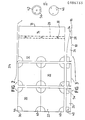
- FIGS. 1 to 3 show part of such a threshold in a state during assembly. Only one ramp plate 10 is shown, but at least two such ramp plates are always necessary for a complete threshold.
- the ramp plate 10 is composed in one piece of a threshold area 12 with a constant height, namely the threshold height, and a wedge area 14 which, starting from the threshold height, ends at a very acute angle and at a leading edge 16 in the plane of the lower surface 18.
- intermediate plates 20 are shown, four of which can be seen in the partial sleeper shown. They have a flat upper driving surface 22, their thickness corresponds to the threshold height.
- Most of the thresholds that occur in practice can already be realized by compiling the elements discussed so far, namely ramp plates 10 and intermediate plates 20.
- the term "plate” is intended to illustrate the flat, tabular design of the two plates 10, 20. Both plates 10, 20 have a prismatic shape, ie one in essence Chen constant cross section over its length.
- the intermediate plate 20 is also cuboid.
- the plates 10, 20 are flat, ie their height is significantly less than their width or length, in the exemplary embodiment shown the threshold height is approximately one fifth of the length dimension of the intermediate plates 20.
- the length of the ramp plate 10 is twice the length (and also Width) of the intermediate plates 20.
- the length of the ramp plate 10 (determined in the direction of travel of a motor vehicle) is also significantly greater than the length (and width) of the intermediate plate 20, in the present example the excess is fifty percent.
- Typical length dimensions for the intermediate plate 20 are fifty centimeters by fifty centimeters.
- the plates 10, 20 have vertical narrow surfaces 24, 26, on which they adjoin one another in the installed state with extensive mutual contact.
- the plates 10, 20 are made of a recycled rubber, in the specific exemplary embodiment a linear rubber material in the form of a crumple cut is used, which is held together by suitable means.
- a linear rubber material in the form of a crumple cut is used, which is held together by suitable means.
- DE-PS 17 20 059 by the applicant.
- the force-reduction factor of the recycled rubber used is in the range of forty percent to sixty percent compared to a sand bed with a standard grain size.
- a rigid reinforcing strip 28 in the form of a U-steel profile is embedded in the ramp plate 10 within the wedge region 14 and approximately in the middle of the length of this wedge region 14. It extends over the entire length of the ramp plate 10, whereby its front ends are visible from the outside. In a modified design, it is dimensioned somewhat shorter than the ramp plate 10, so that its end areas are embedded and protected in the solid material of the recycling rubber.
- Screw holes 30 are provided in the reinforcement strip 28, through which wood screws such as the screw 32 shown in FIG. 1 can be inserted. Channels for the screw guide adjoin the screw holes 30 downwards and upwards, the upwardly extending channel having a sufficient inside diameter to be able to push the screw head through and to be able to tighten the screw 32. This duct is closed by plugs (not shown) at the end of the assembly.
- the sleepers according to the invention are fastened exclusively by means of screws 32.
- screws 32 For this purpose, holes are drilled in the subsurface before assembly, the subsurface usually has sufficient strength since it is mostly formed by concrete or bitumen.
- Dowels are used in the boreholes in a known manner, which expand when screw 32 is screwed in and offer it a secure hold. Screwing forces of, for example, 16 kN per screw 32 are achieved. Overall, the individual components of the sleeper are pressed by the screws 32 as far as possible with their flat lower surfaces 18 against a mounting surface.
- the U-profile of the reinforcement strip 28 has a base width of five centimeters, the height of each of the two legs is approximately half this value, and the material thickness is between eight and ten millimeters.
- the prepared screw holes 30 with the subsequent channels it is possible at any time to subsequently drill additional screw holes 30. In principle, all screw holes 30 could only be drilled during assembly.
- the driving surface 22 of the wedge region 14 runs smoothly and rounded into the driving surface 22 of the threshold region 12.
- the length of the threshold area is one third of the total length of the ramp plate 10.
- the approach angle alpha is approximately eleven degrees in the exemplary embodiment shown.
- the intermediate plates 20 are not reinforced, but this does not in principle exclude the possibility of providing reinforcement there.
- the driving surface 22, in particular of the intermediate plates 20, can be colored black or white, so that zebra crossings can be put together.
- a retroreflective tape is embedded and vulcanized into the driving surface 22, in particular of the wedge area 14 of the ramp plate 10, as the reflection area 34. It reflects the incident light largely independently of the angle of incidence, so that a part of the headlight light of the motor vehicle is reflected back by the reflection region 34, in particular at night, so that a driver can clearly see the threshold.
- FIGS. 1 to 3 and also FIG. which are designed as quarter-circle recesses.
- a further recess, designed as a semicircular recess, is located in the middle of the narrow surface 24 opposite the approach edge 16.
- the recesses 40 are each designed so that the material thickness, starting from the drive surface 22, is reduced to thirty to fifty percent gert is, the lower surfaces 18 remain unaffected.
- the individual cutouts form a common, pot-shaped depression with a cylindrical boundary.
- a pressure part 42 is inserted into them ; is circular disk-shaped and has an outer diameter which largely corresponds to the inner diameter of the overall pot-shaped recess.
- the pressure parts 42 have a central bore through which a screw 32 (see FIG. 1) can be inserted. So that this screw can be inserted comfortably through the underlying, not recessed area of the plates 10, 20, these are recessed at their corner edges 44 or the corresponding points so that in the assembled state of the plates 10, 20 a hole for free passage the screw 32 is formed.
- the intermediate plates 20 are clamped laterally, for example by ramp plates 10, by a curb or the like.
- the intermediate plates 20 are therefore always surrounded by a frame which is fixedly screwed to the mounting surface or is otherwise fastened (curbs) and which prevents them from slipping sideways.
- the pressure parts 42 have a diameter which is approximately one third of the length dimension of the intermediate plates 20. In a specific embodiment, disc-shaped pressure parts 42 with a diameter of twenty centimeters are used. The material thickness is eight millimeters.
- the area remaining above the pressure part 42 down to the level of the driving surface 22 is filled by a stopper 46 which can be connected to the pressure part 42.
- the pressure part 42 has three internally threaded bores into which Allen screws can be screwed, which are supported in the stopper 46.
- the plug 46 is armored.
- corner ramp plates 48 are used in addition to the components discussed so far, which in principle have the same structure as the ramp plates 10, but the base area of which corresponds to an isosceles right-angled triangle. They only have a cutout 40 on their inner corner edge 44, at which the right angle is located, the approach edge 16 and the reinforcing strip 28 run at a forty-five degree angle to the two narrow surfaces 26.
- the curvature of the driving surface 22 is selected such that that no kinks occur laterally in transition to the ramp plates 10.
- FIG. 4 clearly shows the square network of the punctual fastening by means of the screws 32. These cannot be seen in FIG. 4, since the overall pot-shaped recesses are already closed by plugs 46, but the boundary lines of the individual plates 10, 20 and 48 are drawn through. From this and from Figure 1 it can be seen that the prepared holes for the screws 32 are in the intersection of the boundary lines, more precisely on the intersection of the narrow surfaces 24, 26 of adjacent plates 10, 20, 48.
- FIG. 6 finally, is a different design of the V ER- binding of threshold regions 12 with one another or shown with intermediate plates 20, the used plug-in connection corresponds to a large extent of the connector according to DE-OS 34 05 628 of the applicant to 1.
- the plug connector 52 In the central region, that is to say the boundary line between the plates 10, 20, 48, the plug connector 52 has at least one bore for screwing, as has already been described above. Otherwise, the connector largely corresponds to the pressure part 42, but there is no plug.
- Other connectors in particular connectors that can be used in specially provided pockets at the location of the channels 50 in accordance with FIG. 8 of the said publication, are in principle possible.
- the modular system shown is also suitable for areas in the traffic area which are difficult or inaccessible, for example non-accessible traffic islands.
- a strongly rounded curb for example in the form of a quarter bar, is used, which also has an internal reinforcement corresponding to the reinforcement bar 28.
- the other connection is made as described above.
- the greater curvature makes opening more difficult, although a reduction in power is retained.
- the frame function of the outer, reinforced edge parts is retained.
Landscapes
- Engineering & Computer Science (AREA)
- Architecture (AREA)
- Civil Engineering (AREA)
- Structural Engineering (AREA)
- Road Signs Or Road Markings (AREA)
- Road Paving Structures (AREA)
- Refuge Islands, Traffic Blockers, Or Guard Fence (AREA)
- Steroid Compounds (AREA)
- Medicines Containing Material From Animals Or Micro-Organisms (AREA)
Priority Applications (1)
| Application Number | Priority Date | Filing Date | Title |
|---|---|---|---|
| AT85111723T ATE64965T1 (de) | 1984-09-21 | 1985-09-17 | Fahrdynamische schwelle fuer kraftverkehrswege. |
Applications Claiming Priority (2)
| Application Number | Priority Date | Filing Date | Title |
|---|---|---|---|
| DE8427790U | 1984-09-21 | ||
| DE8427790U DE8427790U1 (de) | 1984-09-21 | 1984-09-21 | Fahrdynamische Schwelle für Kraftverkehrswege |
Publications (3)
| Publication Number | Publication Date |
|---|---|
| EP0186733A2 true EP0186733A2 (fr) | 1986-07-09 |
| EP0186733A3 EP0186733A3 (en) | 1987-07-22 |
| EP0186733B1 EP0186733B1 (fr) | 1991-07-03 |
Family
ID=6770915
Family Applications (1)
| Application Number | Title | Priority Date | Filing Date |
|---|---|---|---|
| EP85111723A Expired - Lifetime EP0186733B1 (fr) | 1984-09-21 | 1985-09-17 | Dos d'âne respectant la dynamique du mouvement des véhicules sur des voies de circulation |
Country Status (4)
| Country | Link |
|---|---|
| US (1) | US4697294A (fr) |
| EP (1) | EP0186733B1 (fr) |
| AT (1) | ATE64965T1 (fr) |
| DE (2) | DE8427790U1 (fr) |
Cited By (8)
| Publication number | Priority date | Publication date | Assignee | Title |
|---|---|---|---|---|
| WO1993015274A1 (fr) * | 1992-02-01 | 1993-08-05 | Michael Peter Gifford Hull | Rond-point |
| FR2699199A1 (fr) * | 1992-12-16 | 1994-06-17 | Cibomat | Elément modulaire formant rampe destiné à la réalisation de ralentisseurs ou de passages surélevés pour piétons. |
| WO1998053144A1 (fr) * | 1997-05-21 | 1998-11-26 | Jeffrey Ernest Hope | Structure revetement de sol surelevee |
| FR2772401A1 (fr) * | 1997-12-12 | 1999-06-18 | Barillon Gerard Gerbelot | Dispositif ralentisseur pour vehicules |
| ES2321794A1 (es) * | 2009-03-13 | 2009-06-10 | Javier F. Dominguez Diez | Paso de peatones elevado con señalizacion luminosa. |
| FR3080388A1 (fr) * | 2018-04-23 | 2019-10-25 | Canalisations Regards Prefabrication | Dispositif ralentisseur routier du type coussin berlinois |
| DE102024127027B3 (de) * | 2024-09-19 | 2026-02-12 | Lüft GmbH & Co. KG | Modulares System zur Errichtung von Fahrbahnabgrenzungen auf einer Fahrbahn in Form einer gegenüber der Fahrbahn erhöhten Fläche |
| EP4715119A1 (fr) * | 2024-09-19 | 2026-03-25 | Lüft GmbH & Co. KG | Système modulaire pour ériger des barrières routières sur une chaussée sous forme de surface surélevée par rapport à la chaussée |
Families Citing this family (79)
| Publication number | Priority date | Publication date | Assignee | Title |
|---|---|---|---|---|
| DE8427790U1 (de) * | 1984-09-21 | 1985-01-31 | Berleburger Schaumstoffwerk Gmbh, 5920 Bad Berleburg | Fahrdynamische Schwelle für Kraftverkehrswege |
| FR2590602B1 (fr) * | 1985-11-28 | 1987-12-11 | Basaltine | Ralentisseur de circulation de type dos-d'ane. |
| US4813811A (en) * | 1987-06-23 | 1989-03-21 | Simulators Limited, Inc. | Prefabricated pavement devices |
| US4974991A (en) * | 1989-06-19 | 1990-12-04 | Seid Mandavi | Vehicle speed bump device |
| GB9000906D0 (en) * | 1990-01-16 | 1990-03-14 | R E Rubber Company Limited | Modular speed ramp |
| US5201467A (en) * | 1991-09-03 | 1993-04-13 | Riedel Omni Rubber Products, Inc. | Apparatus for interconnecting elastomeric grade crossing panels |
| US5267367A (en) * | 1992-01-13 | 1993-12-07 | Wegmann Jr Gerald A | Safety ramp and method for protecting hoses and conduits |
| US5446937A (en) * | 1992-09-08 | 1995-09-05 | Pemko Manufacturing Company | Modular ramp system |
| NZ259477A (en) * | 1993-02-04 | 1996-02-27 | Viscount Plastics Pty Ltd | Fastening device; comprises a base plate from which tubular projections extend into bores in pavers, a fastener locking the paver to a projection |
| US5295759A (en) * | 1993-04-13 | 1994-03-22 | The United States Of America As Represented By The Secretary Of The Army | Snow plow compatible speed bumps |
| US5415493A (en) * | 1993-04-13 | 1995-05-16 | The United States Of America As Represented By The Secretary Of The Army | Snow plow compatible speed bumps |
| US5393166A (en) * | 1993-05-10 | 1995-02-28 | Target Recycling Inc. | Reflective marker from recyclable material |
| US5419652A (en) * | 1994-03-16 | 1995-05-30 | U.S. Army Corps Of Engineers As Represented By The Secretary Of The Army | Snow plow compatible speed bumps |
| ES2096520B1 (es) * | 1994-05-24 | 1997-08-16 | Pinturas Jaque S L | Señal horizontal sonora. |
| GB9415410D0 (en) * | 1994-07-23 | 1994-09-21 | Bartingale Peter | Improvements in traffic control islands and calming islands |
| US5509753A (en) * | 1994-11-22 | 1996-04-23 | Thompson; Clinton C. | Retractable speed bump |
| US5775834A (en) * | 1995-08-14 | 1998-07-07 | Jackson; Brian G. | Portable highway warning device with frangible retainer ring |
| CN1198790A (zh) * | 1995-10-05 | 1998-11-11 | 美国3M公司 | 柔性突起的路面标志器及其安装装置和方法 |
| US6395362B1 (en) * | 1996-07-19 | 2002-05-28 | Tac-Fast Georgia, L.L.C. | Anchor sheet framework and subflooring |
| US6460303B1 (en) | 1996-07-19 | 2002-10-08 | Tac-Fast Georgia L.L.C. | Hook and loop anchor sheet module with overlapped edges and sufficient mass to resist buckling |
| US7185473B2 (en) * | 1996-07-19 | 2007-03-06 | Tac-Fast Georgia, L.L.C. | Anchor sheet and anchor sheet module |
| US6298624B1 (en) * | 1996-07-19 | 2001-10-09 | Tac-Fast Georgia, L.L.C. | Anchor sheet and anchor sheet module |
| US20070204556A1 (en) * | 1996-07-19 | 2007-09-06 | Tac-Fast Georgia L.L.C. | Covering module and anchor sheet |
| US20010042350A1 (en) * | 1996-07-19 | 2001-11-22 | Joseph R. Pacione | Covering module and anchor sheet |
| AU139940S (en) * | 1998-02-06 | 2000-03-02 | Illinois Tool Works | A road speed hump component |
| US6174103B1 (en) | 1998-12-04 | 2001-01-16 | Randall N. Stroman | Removable/portable speed bump apparatus |
| US6623206B1 (en) | 1999-04-07 | 2003-09-23 | Pmg, Inc. | Portable speed bump |
| IL146788A0 (en) | 1999-06-07 | 2002-07-25 | Tac Fast Systems Sa | Anchor sheet attachment devices |
| DE60037661T2 (de) * | 1999-07-02 | 2009-01-08 | Excellent Systems A/S | Vorrichtung zur einfachen Überwindung von Höhendifferenzen, insbesondere bei Türschwellen, durch Rollstuhlfahrer |
| US20040034950A1 (en) * | 2000-06-27 | 2004-02-26 | Joseph Massaro | Portable ramp system |
| EP1199408A1 (fr) * | 2000-10-16 | 2002-04-24 | Peter Lüft | Rotonde traversable et méthode de fabrication et d'ancrage d'un support pour une rotonde traversable |
| US7412806B2 (en) * | 2001-12-13 | 2008-08-19 | Tac-Fast Georgia Llc | Structures for creating spaces while installing anchor sheet and attachment piece subfloors |
| US6551192B1 (en) * | 2002-01-29 | 2003-04-22 | Hedstrom Corporation | Obstacle assembly for bikes, skateboards and rollerblades |
| US6782577B2 (en) * | 2002-10-29 | 2004-08-31 | Hedstrom Corporation | Knock-down quarter pipe for skateboarders, bikers and in-line skaters |
| US6860674B2 (en) | 2002-12-27 | 2005-03-01 | Interstate Recycling | Speed bumps formed from tire tread strip laminations |
| MXPA05008225A (es) * | 2003-01-30 | 2006-01-17 | Tac Fast Systems Sa | Hoja de anclaje mejorada. |
| CA2514015A1 (fr) * | 2003-01-30 | 2004-08-12 | Joseph Rocco Pacione | Dalle de moquette, pose, procedes de fabrication et de pose associes |
| CA2513958A1 (fr) * | 2003-01-30 | 2004-08-12 | Joseph Rocco Pacione | Revetement de sol comportant un element decoratif amovible |
| DK1589856T3 (da) * | 2003-01-30 | 2008-08-18 | Tac Fast Systems Sa | System til placering og forbindelse af et forankringsark |
| US7114873B2 (en) * | 2003-07-17 | 2006-10-03 | Omnitek Partners Llc | Adaptive security and protective barriers and traffic control speed bumps |
| US20060003141A1 (en) * | 2004-06-30 | 2006-01-05 | Pacione Joseph R | Floor covering having a removable decorative inlay |
| US20060107609A1 (en) * | 2004-11-12 | 2006-05-25 | Stringer Erin S | Cover for a fastener |
| FR2882376B1 (fr) * | 2005-02-22 | 2007-06-29 | Simat | Equipement de securite et de signalisation routieres et procede d'installation d'un tel equipement |
| US7591605B2 (en) * | 2005-04-28 | 2009-09-22 | Gnr Technologies Inc. | Modular traffic calming devices |
| US7694480B2 (en) * | 2005-06-27 | 2010-04-13 | Niese Michael W | Panel-type subfloor for athletic floor |
| WO2007062134A2 (fr) * | 2005-11-22 | 2007-05-31 | Baranoff Sergei C | Systeme de protection de la surface pour ameliorations d'infrastructure dans un environnement de construction |
| WO2007065072A2 (fr) * | 2005-11-23 | 2007-06-07 | New Pig Corporation | Systemes d'ancrage amovibles pour ralentisseurs dos d'ane et blocs anti-stationnement |
| US20070258764A1 (en) * | 2006-03-03 | 2007-11-08 | New Pig Corporation | One-way speed bump |
| JP2007241887A (ja) * | 2006-03-10 | 2007-09-20 | Fujitsu Component Ltd | キーボード |
| US8288652B2 (en) * | 2006-04-20 | 2012-10-16 | Checkers Industrial Products, Llc | Tapered transition ramp for cable protector with offset center sections |
| US7607186B1 (en) * | 2006-06-20 | 2009-10-27 | Terry L Mitchell | Modular wheelchair ramp |
| CN101162207B (zh) * | 2006-10-13 | 2011-04-13 | 同方威视技术股份有限公司 | 坡台装置和包括它的车载移动式车辆检查系统 |
| US7634876B2 (en) * | 2006-12-08 | 2009-12-22 | Moller Jr Jorgen J | Modular floor locator apparatus |
| US7621691B2 (en) * | 2007-08-13 | 2009-11-24 | Impact Recovery Systems, Inc. | Raised, longitudinal, channelizing separator system |
| US7571507B2 (en) * | 2007-12-21 | 2009-08-11 | Holicki Joseph P | Wheelchair platform and detachable ramp, and methods of constructing and utilizing same |
| US8388261B1 (en) * | 2007-12-31 | 2013-03-05 | Christopher Allen Lane | Road plate securing assembly |
| US20090169298A1 (en) * | 2007-12-31 | 2009-07-02 | Christopher Allen Lane | Road plate securing assembly |
| US20090255066A1 (en) * | 2008-04-11 | 2009-10-15 | Brock Robert D | Rearrangeable interconnectable system for handicap ramps and platforms |
| US8784545B2 (en) | 2011-04-12 | 2014-07-22 | Mathena, Inc. | Shale-gas separating and cleanout system |
| KR101063271B1 (ko) * | 2008-07-29 | 2011-09-07 | 손창섭 | 잔디 보호 매트 |
| US7736087B1 (en) | 2008-12-22 | 2010-06-15 | Plastic Safety Systems, Inc. | Portable highway warning device |
| CA2774386A1 (fr) | 2011-04-15 | 2012-10-15 | Tac-Fast Systems Canada Limited | Procedes et systemes concus pour installer un revetement decoratif |
| US8447509B2 (en) * | 2011-07-13 | 2013-05-21 | Dynamic Research, Inc. | System and method for testing crash avoidance technologies |
| WO2013170137A2 (fr) | 2012-05-11 | 2013-11-14 | Mathena, Inc. | Tableau de commande, et unités d'affichage numérique et capteurs pour ceux-ci |
| USD722084S1 (en) | 2012-07-25 | 2015-02-03 | Christopher A. Lane | Road plate securing assembly |
| AU350921S (en) * | 2013-06-20 | 2013-09-20 | Centor Design Pty Ltd | Sliding door sill |
| AU350915S (en) * | 2013-06-20 | 2013-09-20 | Centor Design Pty Ltd | Sliding door sill |
| USD763414S1 (en) * | 2013-12-10 | 2016-08-09 | Mathena, Inc. | Fluid line drive-over |
| WO2015200431A1 (fr) | 2014-06-25 | 2015-12-30 | Trinty Highway Products, Llc | Dispositif de signalisation routière portatif |
| US10053344B1 (en) * | 2015-02-02 | 2018-08-21 | Camco Manufacturing, Inc. | Leveling system including storage and transport handle |
| US9908692B2 (en) * | 2015-05-06 | 2018-03-06 | ASFI Partners, L.P. | Multi-piece storage tank pad with separate connectors |
| EP3347524B1 (fr) * | 2015-09-11 | 2020-12-23 | Zkxkz, Llc | Carrefour giratoire et méthode de réalisation d'un carrefour giratoire |
| KR101894016B1 (ko) * | 2016-04-15 | 2018-08-31 | 국민대학교 산학협력단 | 타겟 운전체 |
| ITUA20164281A1 (it) * | 2016-06-10 | 2017-12-10 | Eps Italia Srl | Pannelli modulari per la realizzazione di una pavimentazione temporanea calpestabile componibile/scomponibile e metodo per realizzare detta pavimentazione |
| US10036550B1 (en) * | 2016-07-05 | 2018-07-31 | Derrick Reid | Traffic cross-guard reflective mat |
| ES2613752B1 (es) * | 2017-03-31 | 2018-02-09 | Construcciones Y Promociones Coprosa S.A. | Dispositivo reductor de velocidad aplicable a vías de circulación. |
| US10995456B2 (en) | 2018-09-13 | 2021-05-04 | Zkxkz, Llc | Modular roundabout system with interconnectable boards |
| US10711408B1 (en) | 2019-01-07 | 2020-07-14 | Phillip Wayne Divine | Lane construction safety system |
| US11639586B1 (en) * | 2020-12-09 | 2023-05-02 | Joe Rodriguez | Walkway paver |
Family Cites Families (19)
| Publication number | Priority date | Publication date | Assignee | Title |
|---|---|---|---|---|
| US644138A (en) * | 1899-10-04 | 1900-02-27 | Edmund Ketchum | Building wall or partition. |
| GB225807A (en) * | 1923-12-05 | 1925-07-07 | Rubber Latex Res Corp | Improvements in blocks or sheets for paving and like impact or load-receiving purposes |
| US2672660A (en) * | 1949-03-16 | 1954-03-23 | United Carr Fastener Corp | Fastener device |
| GB689791A (en) * | 1950-05-19 | 1953-04-08 | Ind Chemicals Ltd | Improvements relating to means for marking lines on roads |
| DE1190160B (de) * | 1960-04-22 | 1965-04-01 | Beteiligungs & Patentverw Gmbh | Vorrichtung zum Verbinden von nebeneinander angeordneten Platten, insbesondere befahrbaren Hohlfachplatten |
| GB1147694A (en) * | 1966-09-14 | 1969-04-02 | Douglas William Harcourt Freer | Improvements in or relating to pedestrian crossings |
| GB2030197B (en) * | 1978-04-14 | 1983-03-02 | Ondura Ltd | Portable road surface hump |
| GB2036140A (en) * | 1978-11-14 | 1980-06-25 | Sturtivant G | Road hazard warning device |
| DE2905769A1 (de) * | 1979-02-15 | 1980-08-21 | Kraiburg Elastik | Vorrichtung zur verkehrslenkung und verkehrsberuhigung |
| CH642701A5 (de) * | 1979-09-03 | 1984-04-30 | Willi Ruckstuhl | Fahrbahndecke aus einzelnen, miteinander verbundenen elementen. |
| US4312780A (en) * | 1980-09-15 | 1982-01-26 | Air Products And Chemicals, Inc. | Reactivation of spent chromia-alumina catalyst by zinc oxide doping |
| US4577448A (en) * | 1981-06-17 | 1986-03-25 | The British Picker Company, Ltd. | Floors |
| GB2104946B (en) * | 1981-08-11 | 1985-08-07 | Rocol Ltd | Portable road surface ramps |
| US4430837A (en) * | 1981-11-16 | 1984-02-14 | Bell Telephone Laboratories, Incorporated | Fastening arrangement for abutting structural members |
| DE3213423A1 (de) * | 1982-04-10 | 1983-10-27 | Hazard Warning Systems Ltd., Birmingham | Geschwindigkeitsbegrenzungsschwelle |
| DE8221169U1 (de) * | 1982-07-24 | 1983-06-30 | GFL-Sportstättenbau GmbH, 5928 Laasphe | Warnschwelle auf kfz-verkehrsstrassen |
| CA1191304A (fr) * | 1983-02-23 | 1985-08-06 | Richard A. Morrison | Tapis couvre-sol modulaire a lisiere d'assemblage |
| DE8312556U1 (de) * | 1983-04-28 | 1983-10-20 | Linder, Franz, 5000 Köln | Markierungsstein in form eines laenglichen, balkenartigen koerpers |
| DE8427790U1 (de) * | 1984-09-21 | 1985-01-31 | Berleburger Schaumstoffwerk Gmbh, 5920 Bad Berleburg | Fahrdynamische Schwelle für Kraftverkehrswege |
-
1984
- 1984-09-21 DE DE8427790U patent/DE8427790U1/de not_active Expired
-
1985
- 1985-09-17 DE DE8585111723T patent/DE3583388D1/de not_active Expired - Fee Related
- 1985-09-17 AT AT85111723T patent/ATE64965T1/de not_active IP Right Cessation
- 1985-09-17 EP EP85111723A patent/EP0186733B1/fr not_active Expired - Lifetime
- 1985-09-20 US US06/778,511 patent/US4697294A/en not_active Expired - Fee Related
Cited By (10)
| Publication number | Priority date | Publication date | Assignee | Title |
|---|---|---|---|---|
| WO1993015274A1 (fr) * | 1992-02-01 | 1993-08-05 | Michael Peter Gifford Hull | Rond-point |
| FR2699199A1 (fr) * | 1992-12-16 | 1994-06-17 | Cibomat | Elément modulaire formant rampe destiné à la réalisation de ralentisseurs ou de passages surélevés pour piétons. |
| WO1998053144A1 (fr) * | 1997-05-21 | 1998-11-26 | Jeffrey Ernest Hope | Structure revetement de sol surelevee |
| FR2772401A1 (fr) * | 1997-12-12 | 1999-06-18 | Barillon Gerard Gerbelot | Dispositif ralentisseur pour vehicules |
| ES2321794A1 (es) * | 2009-03-13 | 2009-06-10 | Javier F. Dominguez Diez | Paso de peatones elevado con señalizacion luminosa. |
| ES2321794B2 (es) * | 2009-03-13 | 2009-11-20 | Javier F. Dominguez Diez | Paso de peatones elevado con señalizacion luminosa. |
| FR3080388A1 (fr) * | 2018-04-23 | 2019-10-25 | Canalisations Regards Prefabrication | Dispositif ralentisseur routier du type coussin berlinois |
| EP3561180A1 (fr) * | 2018-04-23 | 2019-10-30 | Canalisations Regards Prefabrication | Dispositif ralentisseur routier du type coussin berlinois et son procédé d'installation |
| DE102024127027B3 (de) * | 2024-09-19 | 2026-02-12 | Lüft GmbH & Co. KG | Modulares System zur Errichtung von Fahrbahnabgrenzungen auf einer Fahrbahn in Form einer gegenüber der Fahrbahn erhöhten Fläche |
| EP4715119A1 (fr) * | 2024-09-19 | 2026-03-25 | Lüft GmbH & Co. KG | Système modulaire pour ériger des barrières routières sur une chaussée sous forme de surface surélevée par rapport à la chaussée |
Also Published As
| Publication number | Publication date |
|---|---|
| EP0186733B1 (fr) | 1991-07-03 |
| ATE64965T1 (de) | 1991-07-15 |
| US4697294A (en) | 1987-10-06 |
| DE8427790U1 (de) | 1985-01-31 |
| DE3583388D1 (de) | 1991-08-08 |
| EP0186733A3 (en) | 1987-07-22 |
Similar Documents
| Publication | Publication Date | Title |
|---|---|---|
| EP0186733A2 (fr) | Dos d'âne respectant la dynamique du mouvement des véhicules sur des voies de circulation | |
| EP0014172A1 (fr) | Paroi protectrice servant de dispositif de guidage pour la circulation routière et d'écran anti-bruit pour les riverains | |
| EP1645691B1 (fr) | Structure de transition | |
| EP0126982A1 (fr) | Pierre de marquage ayant la forme d'un corps oblong comme une poutre | |
| DE2819006C2 (de) | Warneinrichtung für richtungsgebundene Fahrbahnen zur Verhinderung des Einfahrens in Gegenrichtung | |
| DE3505097A1 (de) | Strassenpoller und verfahren zu seiner herstellung | |
| DE3415947A1 (de) | Markierungsstein in form eines laenglichen, balkenartigen koerpers | |
| DE2753918A1 (de) | Sicherheitsbauweise fuer schnellstrassen | |
| DE2636105C3 (de) | Bordstein für Fußgängerüberwege | |
| AT402413B (de) | Vorrichtung zur sicherung eines strassenkanaldurchlasses | |
| AT413556B (de) | Fahrbahnaufsatzplatte | |
| DE9106411U1 (de) | Trennschwelle für Straßenverkehrsbereiche | |
| EP1199408A1 (fr) | Rotonde traversable et méthode de fabrication et d'ancrage d'un support pour une rotonde traversable | |
| DE102004020101A1 (de) | Bankettplatte | |
| EP0634527B1 (fr) | Elément de bordure | |
| DE7245452U (de) | Auflegeplatte oder Baustein | |
| DE4317495A1 (de) | Schwelle | |
| DE4137898A1 (de) | Verkehrsvorrichtung fuer eine nicht freigegebene richtung einschlagende bzw. sich in eine nicht freigegebene richtung bewegende verkehrsteilnehmer | |
| DE9114522U1 (de) | Verkehrsvorrichtung für eine nicht freigegebene Richtung einschlagende bzw. sich in eine nicht freigegebene Richtung bewegende Verkehrsteilnehmer | |
| EP1194650A1 (fr) | Element de revetement de sol et revetement de sol obtenu a partir dudit element | |
| DE4034063A1 (de) | Verkehrsleitende vorrichtung in holzbauweise und zur loesbaren befestigung auf einer verkehrsflaeche | |
| DE4337074A1 (de) | Passive Schutzeinrichtung für Verkehrswege, insbesondere beim Fahrbahnwechsel | |
| AT7311U1 (de) | Bankettplatte | |
| AT378388B (de) | Strassenbauliche einrichtung zur beeinflussung des verkehrs mit kraftfahrzeugen | |
| DE202004007659U1 (de) | Bankettplatte |
Legal Events
| Date | Code | Title | Description |
|---|---|---|---|
| PUAI | Public reference made under article 153(3) epc to a published international application that has entered the european phase |
Free format text: ORIGINAL CODE: 0009012 |
|
| AK | Designated contracting states |
Kind code of ref document: A2 Designated state(s): AT BE CH DE FR GB IT LI NL SE |
|
| PUAL | Search report despatched |
Free format text: ORIGINAL CODE: 0009013 |
|
| AK | Designated contracting states |
Kind code of ref document: A3 Designated state(s): AT BE CH DE FR GB IT LI NL SE |
|
| RHK1 | Main classification (correction) |
Ipc: E01F 1/00 |
|
| 17P | Request for examination filed |
Effective date: 19880119 |
|
| RAP1 | Party data changed (applicant data changed or rights of an application transferred) |
Owner name: STADTSPARKASSE KOELN |
|
| RIN1 | Information on inventor provided before grant (corrected) |
Inventor name: SCHAEFER, HARTMUT |
|
| 17Q | First examination report despatched |
Effective date: 19890224 |
|
| GRAA | (expected) grant |
Free format text: ORIGINAL CODE: 0009210 |
|
| AK | Designated contracting states |
Kind code of ref document: B1 Designated state(s): AT BE CH DE FR GB IT LI NL SE |
|
| PG25 | Lapsed in a contracting state [announced via postgrant information from national office to epo] |
Ref country code: SE Effective date: 19910703 Ref country code: NL Effective date: 19910703 Ref country code: IT Free format text: LAPSE BECAUSE OF FAILURE TO SUBMIT A TRANSLATION OF THE DESCRIPTION OR TO PAY THE FEE WITHIN THE PRESCRIBED TIME-LIMIT;WARNING: LAPSES OF ITALIAN PATENTS WITH EFFECTIVE DATE BEFORE 2007 MAY HAVE OCCURRED AT ANY TIME BEFORE 2007. THE CORRECT EFFECTIVE DATE MAY BE DIFFERENT FROM THE ONE RECORDED. Effective date: 19910703 Ref country code: GB Effective date: 19910703 Ref country code: FR Effective date: 19910703 Ref country code: BE Effective date: 19910703 |
|
| REF | Corresponds to: |
Ref document number: 64965 Country of ref document: AT Date of ref document: 19910715 Kind code of ref document: T |
|
| REF | Corresponds to: |
Ref document number: 3583388 Country of ref document: DE Date of ref document: 19910808 |
|
| PG25 | Lapsed in a contracting state [announced via postgrant information from national office to epo] |
Ref country code: AT Effective date: 19910917 |
|
| PG25 | Lapsed in a contracting state [announced via postgrant information from national office to epo] |
Ref country code: LI Free format text: LAPSE BECAUSE OF NON-PAYMENT OF DUE FEES Effective date: 19910930 Ref country code: CH Free format text: LAPSE BECAUSE OF NON-PAYMENT OF DUE FEES Effective date: 19910930 |
|
| EN | Fr: translation not filed | ||
| NLV1 | Nl: lapsed or annulled due to failure to fulfill the requirements of art. 29p and 29m of the patents act | ||
| GBV | Gb: ep patent (uk) treated as always having been void in accordance with gb section 77(7)/1977 [no translation filed] | ||
| PLBI | Opposition filed |
Free format text: ORIGINAL CODE: 0009260 |
|
| 26 | Opposition filed |
Opponent name: GUMMI-MAYER (STIFTUNG & CO.) Effective date: 19920228 |
|
| REG | Reference to a national code |
Ref country code: CH Ref legal event code: PL |
|
| PG25 | Lapsed in a contracting state [announced via postgrant information from national office to epo] |
Ref country code: DE Effective date: 19920602 |
|
| RDAG | Patent revoked |
Free format text: ORIGINAL CODE: 0009271 |
|
| STAA | Information on the status of an ep patent application or granted ep patent |
Free format text: STATUS: PATENT REVOKED |
|
| 27W | Patent revoked |
Effective date: 19940820 |