EP0186735A2 - War head - Google Patents
War head Download PDFInfo
- Publication number
- EP0186735A2 EP0186735A2 EP19850111925 EP85111925A EP0186735A2 EP 0186735 A2 EP0186735 A2 EP 0186735A2 EP 19850111925 EP19850111925 EP 19850111925 EP 85111925 A EP85111925 A EP 85111925A EP 0186735 A2 EP0186735 A2 EP 0186735A2
- Authority
- EP
- European Patent Office
- Prior art keywords
- warhead
- housing
- wire mesh
- warhead housing
- produced
- Prior art date
- Legal status (The legal status is an assumption and is not a legal conclusion. Google has not performed a legal analysis and makes no representation as to the accuracy of the status listed.)
- Withdrawn
Links
- 229910052751 metal Inorganic materials 0.000 claims abstract description 9
- 239000002184 metal Substances 0.000 claims abstract description 9
- 238000000034 method Methods 0.000 claims abstract description 6
- 229910000831 Steel Inorganic materials 0.000 claims description 5
- 239000010959 steel Substances 0.000 claims description 5
- WFKWXMTUELFFGS-UHFFFAOYSA-N tungsten Chemical compound [W] WFKWXMTUELFFGS-UHFFFAOYSA-N 0.000 claims description 2
- 229910001385 heavy metal Inorganic materials 0.000 claims 1
- 229910052721 tungsten Inorganic materials 0.000 claims 1
- 239000010937 tungsten Substances 0.000 claims 1
- 230000000694 effects Effects 0.000 abstract description 4
- 238000013467 fragmentation Methods 0.000 description 3
- 238000006062 fragmentation reaction Methods 0.000 description 3
- 230000015572 biosynthetic process Effects 0.000 description 2
- 239000012634 fragment Substances 0.000 description 2
- 238000004519 manufacturing process Methods 0.000 description 2
- 206010041662 Splinter Diseases 0.000 description 1
- 230000002349 favourable effect Effects 0.000 description 1
- 239000000463 material Substances 0.000 description 1
- 238000005096 rolling process Methods 0.000 description 1
- 238000007493 shaping process Methods 0.000 description 1
- 239000007858 starting material Substances 0.000 description 1
Images
Classifications
-
- F—MECHANICAL ENGINEERING; LIGHTING; HEATING; WEAPONS; BLASTING
- F42—AMMUNITION; BLASTING
- F42B—EXPLOSIVE CHARGES, e.g. FOR BLASTING, FIREWORKS, AMMUNITION
- F42B12/00—Projectiles, missiles or mines characterised by the warhead, the intended effect, or the material
- F42B12/02—Projectiles, missiles or mines characterised by the warhead, the intended effect, or the material characterised by the warhead or the intended effect
- F42B12/20—Projectiles, missiles or mines characterised by the warhead, the intended effect, or the material characterised by the warhead or the intended effect of high-explosive type
- F42B12/22—Projectiles, missiles or mines characterised by the warhead, the intended effect, or the material characterised by the warhead or the intended effect of high-explosive type with fragmentation-hull construction
Definitions
- the innovation relates to a warhead according to the preamble of claim 1.
- Such a warhead is known from DE-OS 224 2930.
- a warhead of this type is transported in large numbers by a missile or projectile over a target area and is ejected there, in order to then either fall down or braked down onto the target area.
- the known warhead comprises a warhead housing in which a shaped charge is arranged and an igniter connected to the warhead housing.
- an additional splinter-forming effect is also sought, which can be achieved by appropriate pre-fragmentation of the warhead housing. This pre-fragmentation, on the one hand, weakens the casing shell and, on the other hand, requires work steps that make the warhead more expensive, particularly in the case of casing shells made of high-quality steel.
- the innovation is an object / specify an improved in terms of fragmentation warhead, which is cheaper to produce.
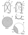
- FIG. 1 shows a longitudinal section through a warhead 10, which includes a warhead housing 11 and a detonator 12 connected to it, with the omission of the innovation of insignificant parts.
- the starting material for the warhead housing 11 is a circular blank 20 (circular metal piece), which is shown schematically in FIG.
- the cup-shaped warhead housing 11 is preferably produced from the blank 20 by a shaping process such as deep drawing.
- a wire mesh 21 is arranged on the round blank 20 before the deep-drawing process and rolled into the surface of the round blank 20.
- the round blank 20 is then subjected to the forming process, so that the warhead housing 11 shown in FIG. 1 is produced.
- the wire mesh 21 is arranged lying within the cup-shaped warhead housing 11.
- the rolled-in and with formed wire mesh 21 favors the desired splitting effect when the warhead 10 is activated.
- FIGS. 3, 4 and 5 show a highly schematic longitudinal section of the warhead 10, while FIG. 4 shows a cross section through the warhead housing along the line 4 - 4 of Figure 3.
- FIG. 5 again shows a round blank as the starting product for the manufacture of the warhead housing of the warhead 10 according to FIG. 3.
- the warhead housing 11 of the warhead 10 according to FIG. 3 consists of a multilayer structure and in particular comprises two layers 11 a, 11 b, which enclose a wire mesh 21 between them.
- This warhead is expediently produced from a round blank 50 (FIG. 5), which consists of two metal layers 51 a, 51 b lying one above the other, which enclose a wire mesh 21 between them.
- This circular blank 50 is produced, for example, by first placing the wire mesh 21 on the first metal layer 51 a and covering it with the second metal layer 51. This layer structure is then connected to one another by rolling.
- the warhead housing 11 is produced again from the round blank 50 by a reshaping process.
- the wire mesh 21 lying between the layers 11 a, 11 b of the warhead 11 in turn promotes the formation of fragments.
- the wire mesh 21 can be made of the same metal, for example steel, as the warhead housing 11 itself. A particularly favorable splintering is achieved, however, if the wire mesh 21 consists of a wire mesh that has different mechanical and / or thermal properties as the material of the warhead housing 11 has. If, for example, the warhead housing 11 is made of steel, the wire mesh 21 can expediently be made of tungsten wire.
Landscapes
- Engineering & Computer Science (AREA)
- Chemical & Material Sciences (AREA)
- Combustion & Propulsion (AREA)
- General Engineering & Computer Science (AREA)
- Radar Systems Or Details Thereof (AREA)
- Powder Metallurgy (AREA)
- Aerials With Secondary Devices (AREA)
Abstract
Description
Die Neuerung betrifft einen Gefechtskopf nach dem Oberbegriff des Anspruchs 1.The innovation relates to a warhead according to the preamble of claim 1.
Ein solcher Gefechtskopf ist aus der DE-OS 224 2930 bekannt. Ein Gefechtskopf dieser Art wird in größerer Anzahl von einem Flugkörper oder Geschoß über ein Zielgebiet transportiert und dort ausgestoßen, um dann entweder gebremst oder ungebremst auf das Zielgebiet hinabzusinken. Der bekannte Gefechtskopf umfaßt ein Gefechtskopfgehäuse in dem eine Hohlladung angeordnet ist und einen mit dem Gefechtskopfgehäuse verbundenen Zünder. Neben der panzerbrechenden Hohlladungswirkung wird zwecks universellerer Verwendbarkeit des Gefechtskopfes auch eine zusätzliche splitterbildende Wirkung angestrebt, die durch entsprechende Vorfragmentierung des Gefechtskopfgehäuses erreichbar ist. Diese Vorfragmentierung schwächt jedoch einerseits den Gehäusemantel und erfordert andererseits , gerade bei Gehäusemänteln aus hochwertigen Stahlarten, den Gefechtskopf verteuernde Arbeitsschritte.Such a warhead is known from DE-OS 224 2930. A warhead of this type is transported in large numbers by a missile or projectile over a target area and is ejected there, in order to then either fall down or braked down onto the target area. The known warhead comprises a warhead housing in which a shaped charge is arranged and an igniter connected to the warhead housing. In addition to the armor-piercing shaped charge effect, in order to make the warhead more universally usable, an additional splinter-forming effect is also sought, which can be achieved by appropriate pre-fragmentation of the warhead housing. This pre-fragmentation, on the one hand, weakens the casing shell and, on the other hand, requires work steps that make the warhead more expensive, particularly in the case of casing shells made of high-quality steel.
Der Neuerung liegt die Aufgabe zugrunde/einen hinsichtlich der Splitterwirkung verbesserten Gefechtskopf anzugeben, der preiswerter herstellbar ist.The innovation is an object / specify an improved in terms of fragmentation warhead, which is cheaper to produce.
Diese Aufgabe wird durch die in Schutzanspruch 1 angegebene Neuerung gelöst. Vorteilhafte Ausgestaltungen gehen aus den Unteransprüchen hervor.This object is achieved by the innovation specified in protection claim 1. Advantageous refinements result from the subclaims in front.
Die Neuerung wird nachfolgend , unter Bezug auf die Zeichnung, näher erläutert. Dabei zeigt:
- Figur 1: einen Längsschnitt durch das Gefachtskopfgehäuse;
- Figur 2: eine Aufsicht auf eine aus Metall bestehende Ronde, aus der der Gefechtskopf hergestellt ist;
- Figur 3: ein weiteres Ausführungsbeispiel im Längsschnitt;
- Figur 4: einen Querschnitt durch das Ausführungsbeispiel nach Fig. 3;
- Figur 5: eine Ronde zur Herstellung des Gefechtskopfgehäuses.
- Figure 1: shows a longitudinal section through the compartment head housing;
- Figure 2 is a plan view of a metal round blank from which the warhead is made;
- Figure 3: another embodiment in longitudinal section;
- Figure 4 shows a cross section through the embodiment of FIG. 3;
- Figure 5: a round blank for the manufacture of the warhead housing.
Figur 1 zeigt, unter Weglassung für die Neuerung unwesentlicher Teile, einen Längsschnitt durch einen Gefechtskopf 10, der ein Gefechtskopfgehäuse 11 und einen damit verbundenen Zünder 12 umfaßt. Ausgangsmaterial für das Gefechtskopfgehäuse 11 ist eine Ronde 20 (kreisförmiges MetallstOck), die schematisch in Figur 2 dargestellt ist. Aus der Ronde 20 entsteht das topfförmig ausgebildete Gefechtskopfgehäuse 11 vorzugsweise durch einen Umformvorgang wie Tiefziehen. Um die Splitterbildung des Gefechtskopfgehäuses 11 zu fördern, wird vor dem Tiefziehvorgang auf der Ronde 20 ein Drahtgeflecht 21 angeordnet und in die Oberfläche der Ronde 20 eingewalzt. Anschließend wird die Ronde 20 dem Umformvorgang unterzogen, sodaß das in Figur 1 dargestellte Gefechtskopfgehäuse 11 entsteht. Bei diesem Ausführungsbeispiel ist das Drahtgeflecht 21 innerhalb des topfförmigen Gefechtskopfgehäuses 11 liegend angeordnet. Alternativ ist es möglich,den Umformvorgang so durchzuführen, daß beim ertigen Gefechtskopfgehäuse 11 das Drahtgeflecht 21 auf der Außenfläche zu liegen kommt. Das eingewalzte und mit umgeformte Drahtgeflecht 21 begünstigt die gewünschte Splitterwirkung bei Aktivierung des Gefechtskopfes 10.FIG. 1 shows a longitudinal section through a
Eine weitere Ausgestaltung der Neuerung wird anhand von Figur 3, 4 und Figur 5 beschrieben. Dabei zeigt Figur 3 wiederum einen stark schematisierten Längsschnitt des Gefechtskopfes 10, während Figur 4 einen Querschnitt durch das Gefechtskopfgehäuse entlang der Linie 4 - 4 nach Figur 3 darstellt. Figur 5 zeigt wiederum eine Ronde als Ausgangsprodukt für die Herstellung des Gefechtskopfgehäuses des Gefechtskopfes 10 nach Figur 3.A further embodiment of the innovation is described with reference to FIGS. 3, 4 and 5. 3 shows a highly schematic longitudinal section of the
Abweichend zum Ausführungsbeispiel nach Figur 1 besteht das Gefechtskopfgehäuse 11 des Gefechtskopfes 10 gemäß Fig. 3 aus einem mehrschichtigen Aufbau und umfaßt insbesondere zwei Schichten 11 a, 11 b, die ein Drahtgeflecht 21 zwischen sich einschließen. Dieser Gefechtskopf wird zweckmäßig aus einer Ronde 50 (Fig. 5) hergestellt, die aus zwei übereinanderliegenden Metallschichten 51 a, 51 b besteht, die ein Drahtgeflecht 21 zwischen sich einschließen. Diese Ronde 50 wird beispielsweise dadurch hergestellt, daß auf die erste Metallschicht 51 a zunächst das Drahtgeflecht 21 aufgelegt und mit der zweiten Metallschicht 51 abgedeckt wird. Anschließend wird dieser Schichtaufbau durch Walzen miteinander verbunden. Schließlich wird,wiederum durch einen Umformvorgang, aus der Ronde 50 das Gefechtskopfgehäuse 11 hergestellt. Das zwischen den Schichten 11 a, 11 b des Gefechtskopfes 11 liegende Drahtgeflecht 21 fördert wiederum die Splitterbildung.In contrast to the exemplary embodiment according to FIG. 1, the
Das Drahtgeflecht 21 kann aus dem gleichen Metall, beispielsweise Stahl, bestehen wie das Gefechtskopfgehäuse 11 selbst. Eine besonders günstige Splitterbildung wird jedoch dann erzielt, wenn das Drahtgeflecht 21 aus einem Drahtgeflecht besteht, das unterschiedliche mechanische und/ oder thermische Eigenschaften wie das Material des Gefechtskopfgehäuses 11 aufweist. Wenn beispielsweise das Gefechtskopfgehäuse 11 aus Stahl besteht, kann das Drahtgeflecht 21 zweckmäßig aus Wolframdraht hergestellt werden.The
Claims (4)
Applications Claiming Priority (2)
| Application Number | Priority Date | Filing Date | Title |
|---|---|---|---|
| DE19848427780 DE8427780U1 (en) | 1984-09-21 | 1984-09-21 | SKULL HEAD |
| DE8427780U | 1984-09-21 |
Publications (1)
| Publication Number | Publication Date |
|---|---|
| EP0186735A2 true EP0186735A2 (en) | 1986-07-09 |
Family
ID=6770905
Family Applications (1)
| Application Number | Title | Priority Date | Filing Date |
|---|---|---|---|
| EP19850111925 Withdrawn EP0186735A2 (en) | 1984-09-21 | 1985-09-20 | War head |
Country Status (3)
| Country | Link |
|---|---|
| EP (1) | EP0186735A2 (en) |
| DE (1) | DE8427780U1 (en) |
| ES (1) | ES289135Y (en) |
Cited By (3)
| Publication number | Priority date | Publication date | Assignee | Title |
|---|---|---|---|---|
| EP0357514A1 (en) * | 1988-09-02 | 1990-03-07 | Thomson-Brandt Armements | Ammunition protective envelope comprising means breaking up thereof |
| GB2368895A (en) * | 2000-11-08 | 2002-05-15 | Schlumberger Holdings | Perforating charge case |
| WO2008083800A1 (en) * | 2007-01-08 | 2008-07-17 | Rheinmetall Waffe Munition Gmbh | Explosive shell |
Families Citing this family (1)
| Publication number | Priority date | Publication date | Assignee | Title |
|---|---|---|---|---|
| NO893032L (en) * | 1988-10-27 | 1990-04-30 | Oerlikon Buehrle Ag | PROCEDURE FOR MANUFACTURING A SPLINT COAT. |
-
1984
- 1984-09-21 DE DE19848427780 patent/DE8427780U1/en not_active Expired
-
1985
- 1985-09-20 ES ES1985289135U patent/ES289135Y/en not_active Expired
- 1985-09-20 EP EP19850111925 patent/EP0186735A2/en not_active Withdrawn
Cited By (6)
| Publication number | Priority date | Publication date | Assignee | Title |
|---|---|---|---|---|
| EP0357514A1 (en) * | 1988-09-02 | 1990-03-07 | Thomson-Brandt Armements | Ammunition protective envelope comprising means breaking up thereof |
| FR2637065A1 (en) * | 1988-09-02 | 1990-03-30 | Thomson Brandt Armements | AMMUNITION PROTECTIVE COVER COMPRISING MEANS FOR CUTTING IT |
| US4986188A (en) * | 1988-09-02 | 1991-01-22 | Thomson-Brandt Armements | Protective casing for munitions having means enabling it to be broken through |
| GB2368895A (en) * | 2000-11-08 | 2002-05-15 | Schlumberger Holdings | Perforating charge case |
| GB2368895B (en) * | 2000-11-08 | 2003-07-09 | Schlumberger Holdings | Perforating charge case |
| WO2008083800A1 (en) * | 2007-01-08 | 2008-07-17 | Rheinmetall Waffe Munition Gmbh | Explosive shell |
Also Published As
| Publication number | Publication date |
|---|---|
| ES289135U (en) | 1986-03-01 |
| DE8427780U1 (en) | 1985-05-15 |
| ES289135Y (en) | 1986-10-01 |
Similar Documents
| Publication | Publication Date | Title |
|---|---|---|
| EP0101795B1 (en) | Fragmentation projectile with splinter effect | |
| DE60108817T2 (en) | Explosive projectile with a splinter coat | |
| EP0350572B1 (en) | Splinter plate in front of an explosive charge | |
| EP0344224B1 (en) | Fragmentation shell for a metallic explosive object and manufacturing process | |
| DE3528371A1 (en) | CHARGE | |
| CH637206A5 (en) | BULLET FOR HANDGUNS. | |
| DE19758460B4 (en) | Projectile-forming charge | |
| DE2557676A1 (en) | Projectile contg. fragments of depleted uranium alloy - giving high penetrating power esp. armour piercing and incendiary action | |
| EP0328877A1 (en) | Projectile with a fragmenting shell | |
| US4774745A (en) | Method of producing fragmentation pattern in military projectiles | |
| US4977657A (en) | Method of producing a fragmentation jacket | |
| EP0030809A2 (en) | Improvements in or relating to explosive fragmentation devices | |
| EP0918206B1 (en) | Fragmentation casing for ammunition | |
| DE2852334C2 (en) | ||
| DE8427780U1 (en) | SKULL HEAD | |
| DE3822375C2 (en) | ||
| DE19736298B4 (en) | Method and device for delaboring grenades with shaped charge | |
| DE2923877A1 (en) | Controlled fragmentation explosive shell casing - has single or double high temp. wire mesh grids embedded in steel casing | |
| EP1304540A2 (en) | Ammunition with a profiled explosive charge | |
| DE3217724C2 (en) | ||
| DE4139371C1 (en) | Airborne target missile head has main charge enclosed by cylindrical sleeves incorporating charges detonated for ejection of sleeve on side facing towards target before detonation of main charge | |
| EP0254800A1 (en) | Hollow charge | |
| EP0183929A2 (en) | War head | |
| DE3932825C2 (en) | ||
| DE2936749A1 (en) | AMMUNITION |
Legal Events
| Date | Code | Title | Description |
|---|---|---|---|
| PUAI | Public reference made under article 153(3) epc to a published international application that has entered the european phase |
Free format text: ORIGINAL CODE: 0009012 |
|
| AK | Designated contracting states |
Kind code of ref document: A2 Designated state(s): DE FR GB IT NL SE |
|
| STAA | Information on the status of an ep patent application or granted ep patent |
Free format text: STATUS: THE APPLICATION HAS BEEN WITHDRAWN |
|
| 18W | Application withdrawn |
Withdrawal date: 19880727 |
|
| RIN1 | Information on inventor provided before grant (corrected) |
Inventor name: BACKSTEIN, GUENTER |