EP0186761A2 - Plaque-déversoir réglable pour centrifugeuse à bol plein comportant une vis sans fin - Google Patents
Plaque-déversoir réglable pour centrifugeuse à bol plein comportant une vis sans fin Download PDFInfo
- Publication number
- EP0186761A2 EP0186761A2 EP85114275A EP85114275A EP0186761A2 EP 0186761 A2 EP0186761 A2 EP 0186761A2 EP 85114275 A EP85114275 A EP 85114275A EP 85114275 A EP85114275 A EP 85114275A EP 0186761 A2 EP0186761 A2 EP 0186761A2
- Authority
- EP
- European Patent Office
- Prior art keywords
- weir plate
- weir
- axis
- plate according
- cover
- Prior art date
- Legal status (The legal status is an assumption and is not a legal conclusion. Google has not performed a legal analysis and makes no representation as to the accuracy of the status listed.)
- Granted
Links
Images

Classifications
-
- B—PERFORMING OPERATIONS; TRANSPORTING
- B04—CENTRIFUGAL APPARATUS OR MACHINES FOR CARRYING-OUT PHYSICAL OR CHEMICAL PROCESSES
- B04B—CENTRIFUGES
- B04B1/00—Centrifuges with rotary bowls provided with solid jackets for separating predominantly liquid mixtures with or without solid particles
- B04B1/20—Centrifuges with rotary bowls provided with solid jackets for separating predominantly liquid mixtures with or without solid particles discharging solid particles from the bowl by a conveying screw coaxial with the bowl axis and rotating relatively to the bowl
- B04B2001/2083—Configuration of liquid outlets
Definitions
- the invention relates to an adjustable weir plate for solid bowl screw centrifuges with the features of the preamble of claim 1.
- Solid-bowl screw centrifuges of the type in question are used, among other things, for very difficult separation tasks that require a very precise adjustment of the pond height in the centrifuge separation area through a finely variable weir adjustment for the liquid drain in order to achieve optimal separation results, for example in the area of sludge that is difficult to convey. But there is also a need to make the weir height adjustable.
- weir plates which can be variably adjusted have been used, in such a way that they have a plurality of bores in their side areas through which the two fixing screws are guided, depending on the choice of the radial position of the plate and thus the weir diameter.
- These plate sets must be made available, kept in stock and used in the correct assignment, which requires a correspondingly large amount of effort.
- weir plates which are round with respect to the outer circumference and which have a bore arranged eccentrically to the outer circumference, through which the liquid phase is discharged.
- These weir plates can be fixed in different rotational positions at a distance from bores arranged in the peripheral side area, so that correspondingly different spacing positions the bores are adjustable to the axis of rotation of the centrifuge.
- the diameter of the eccentric bores within the weir disks is relatively small compared to that of the drain openings, which adversely affects the amount of liquid that can be removed per unit of time. When the throughput changes, the weir accumulates at different heights. This is contrary to the exact weir setting desired.
- the size and / or number of the drain openings in the jacket cover of the centrifuge is limited for reasons of strength.
- weir-shaped weir disks the boundary of which extends outside the circular circumference and serves as an overflow edge which extends over the opening width of the drain opening and is curved to follow the circumferential path of the weir diameter formed by it.
- a separate set of weir plates is required for each of the weir diameters to be set.
- the invention has for its object to provide a weir plate of the type mentioned which, after manufacture, handling and warehousing, enables a fine-stage weir height adjustment over a large diameter range in the most cost-effective and simple manner.
- the displaceability of the weir plate according to the invention in the radial direction to the centrifuge axis by means of a rotatably mounted adjusting member and the fixing in the respectively set position makes it possible to use one and the other the same weir plate per drain opening to set a large number of finely spaced weir diameters, the overflow edge of which extends over the width of the drain opening, so that its drainage capacity is fully utilized.
- the adjusting member can be designed as a lever, the fulcrum of which is fixed to the jacket cover and the pivotable end of which engages on an attack surface of the weir plate or vice versa.
- a lever or the like is sufficient, it being possible to ensure the correct position of the overflow edge by sliding the weir plate.
- the lever is designed as an eccentric disc, which is further preferably inserted into a circular recess in the weir plate.
- two such eccentric discs are provided, the axes of rotation of which are formed by the fastening screws for the weir plate. There is a screw in each side area of the weir plate.
- the individual settings - in particular staggered at a distance of 1 mm - the weir diameter are fixed by markings of the position of rotation for the setting member, in particular by positive engagement designs, for example in the manner of tongue and groove. This enables the weir diameter to be set absolutely the same for all weir plates, which is important for the exact sequence and balancing of the centrifuge.
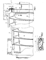
- the centrifuge 1 consists of a cylindrical section - on the right in the picture - which merges to the left into a conical section, a central section with the transition being omitted.
- the screw 12 Inside the jacket 11 of the centrifuge, the screw 12 is arranged, the outer contour of which is adapted to the inner wall of the jacket 11.
- the centrifuge is operated at high revolutions, whereby gear measures, not shown, ensure that the screw 12 rotates at a low differential speed relative to the casing 11, such that, due to the centrifugal force, solid settling on the inner wall of the casing is a non-illustrated in the Separation chamber 14 continuously fed suspension is transported from the screw spiral to the solid discharge 13 in the end region of the conical section of the centrifuge.
- the liquid phase of the suspension which clears due to the higher specific weight of the solid, is therefore present in the radially innermost area of the suspension pond in the separation chamber, with an optimum separation result depending on the type of suspension - separation quality and separation throughput - with the parallel dimension of the pond in Separation space is dependent.
- the radial dimension pond determined by adjustable weir p la tt s, which are set in the range of drain openings 15 in the shell cover 16.
- adjustable weir p la tt s which are set in the range of drain openings 15 in the shell cover 16.
- the drainage openings 15 are arranged distributed over the circumference of the cover, their number and / or their opening width is limited by the strength requirements of the cover.
- a radially outer portion of the drain openings 15 is covered by weir plates 17, which are held by screws 18 and adjustable by adjusting members 19 in a manner to be described in more detail with regard to their distance from the axis of rotation 20 of the centrifuge.
- the overflow edge 21 or 22 of the weir plates facing the centrifuge axis 20 determines the weir diameter and thus the radial thickness of the suspension pond which forms a cylindrical shape in rotation in the separating space 14.
- the overflow edges 21 and 22 are approximately the circumferential profile of the circular arc determined by an average weir diameter subsequently curved, as can be seen in FIG. 2.
- the setting of different weir diameters is described using an exemplary embodiment of the weir plate 17 for one of the drain openings 15, each of which is assigned a corresponding weir plate.
- the adjusting members 19 each have a circular outer circumference and thus a circular cylindrical circumferential surface around the central axis 23, which is offset eccentrically from the parallel screw axis 24 of the associated screw 18 by the distance e.
- the weir plate 17 has a plate recess 27 for the two adjusting members 19 designed as eccentric disks and the associated screws 18, which as seen from the insertion side of the screw 18 as section 29 with a circular cylinder
- the inner circumferential surface 25 is formed around the center axis 23 of the adjusting member 19 inserted in the section 29, the circumferential surface 26 of the adjusting member 19 abutting against the inner circumferential surface of the portion 29 serving as the engagement surface 25 with a clearance fit.
- a pivot bearing bore 28 is made in the adjusting member 19, which with a clearance fit accommodates a cylindrical section of the screw bolt below the screw head of the screw 18.
- an opening region 31 is introduced into the bottom of the section 29 of the plate recess 27, which has a smaller diameter than the section 29 and through which the shaft of the screw 18 is guided in order to thread into the side of the drain opening 15 to be screwed into the jacket cover 16 and thus to fix the weir plate 17 thereon.
- a shoulder 30 against which or the surface 32 of which the setting member 19 acted upon by the screw 18 in the fixed state is held.
- the opening region 31 of the plate recess 27 is held so far that the weir plate can move around the shaft of the screw 18 in any possible rotational position setting of the adjusting member and thus corresponding radial displacement.
- the screw shaft is so long that the screw can be loosened so far without leaving the thread that the adjusting member 19 can be removed from its engagement in the section 29 and reinserted in a different rotational position.
- the setting members 19 can be inserted in specific, precisely positioned positions of rotation, marked by form-fitting engagement, in the respectively associated section 29 of the plate recess 27, as in particular 3 shows.
- the form-fitting engagement formation is made here in such a way that in the circumferential area of the adjusting members 19 parallel to the center axis 23, radially outwardly open in cross-section approximately semi-circular recesses 33 are incorporated, which interrupt the circumferential surface 26, while on the inner circumferential surface 25 of section 29 of the plate recess 27, a correspondingly approximately semicircular projection is provided, which engages in one of the cutouts 33 either selectively or depending on the rotational position of the setting member 19.
- this projection is formed by approximately one longitudinal half of a pin 34, for example in the form of a grooved pin, which is inserted parallel to the center axis 23 into a bore made in the transition between the heel area 30 and the inner peripheral surface 25, which is aligned in one approximately semicircular recess 40 runs out, which lies parallel to the center axis 23 in the inner peripheral surface 25 of the section 29.
- ⁇ is the angle about the center axis 23 of the adjusting members 19, under which a recess 33 is arranged, which belongs to a certain gradation Ar.
- the even-numbered recesses 2, 4, 6, 8 are arranged on one half 37 of the circumference and the odd-numbered recesses 1, 3, 5, 7, 9 on the other circumferential half 36 of the adjusting members 19, while the recesses 0 and 10 are approximately in Weir radius direction.
Landscapes
- Centrifugal Separators (AREA)
Applications Claiming Priority (2)
| Application Number | Priority Date | Filing Date | Title |
|---|---|---|---|
| DE3446166 | 1984-12-18 | ||
| DE3446166A DE3446166C2 (de) | 1984-12-18 | 1984-12-18 | Einstellbare Wehrplatte für Vollmantel-Schneckenzentrifugen |
Publications (3)
| Publication Number | Publication Date |
|---|---|
| EP0186761A2 true EP0186761A2 (fr) | 1986-07-09 |
| EP0186761A3 EP0186761A3 (en) | 1987-12-23 |
| EP0186761B1 EP0186761B1 (fr) | 1990-10-17 |
Family
ID=6253111
Family Applications (1)
| Application Number | Title | Priority Date | Filing Date |
|---|---|---|---|
| EP85114275A Expired - Lifetime EP0186761B1 (fr) | 1984-12-18 | 1985-11-08 | Plaque-déversoir réglable pour centrifugeuse à bol plein comportant une vis sans fin |
Country Status (3)
| Country | Link |
|---|---|
| EP (1) | EP0186761B1 (fr) |
| DE (2) | DE3446166C2 (fr) |
| DK (1) | DK169466B1 (fr) |
Cited By (4)
| Publication number | Priority date | Publication date | Assignee | Title |
|---|---|---|---|---|
| WO1992021445A1 (fr) * | 1991-06-06 | 1992-12-10 | Alfa-Laval Separation, Inc. | Retenue gonflable pour centrifugeuse de decanteur |
| US7326169B2 (en) * | 2002-01-30 | 2008-02-05 | Westfalia Separator Ag | Full-jacket helix centrifuge with a weir |
| WO2014117760A1 (fr) * | 2013-01-29 | 2014-08-07 | Flottweg Se | Centrifugeuse à vis à bol plein dotée d'un bord faisant barrage |
| GB2513358A (en) * | 2013-04-24 | 2014-10-29 | Nat Oilwell Varco Lp | A centrifuge and a control system therefor |
Families Citing this family (3)
| Publication number | Priority date | Publication date | Assignee | Title |
|---|---|---|---|---|
| DE102004019368B4 (de) * | 2004-04-21 | 2008-03-27 | Flottweg Gmbh & Co. Kgaa | Wehreinrichtung für eine Zentrifuge |
| US8579783B2 (en) | 2009-07-02 | 2013-11-12 | Andritz S.A.S. | Weir and choke plate for solid bowl centrifuge |
| CN102225380A (zh) * | 2011-04-26 | 2011-10-26 | 江苏迈安德食品机械有限公司 | 卧螺离心机的液池水位调节装置 |
Family Cites Families (3)
| Publication number | Priority date | Publication date | Assignee | Title |
|---|---|---|---|---|
| GB297914A (en) * | 1927-07-26 | 1928-10-04 | Sunderland Forge & Engineering | Improvements in and relating to centrifugal separators |
| US3081026A (en) * | 1959-03-20 | 1963-03-12 | Black Clawson Co | Centrifuge |
| DE1782260A1 (de) * | 1967-08-23 | 1971-08-12 | Alfa Laval Ab | Zentrifuge |
-
1984
- 1984-12-18 DE DE3446166A patent/DE3446166C2/de not_active Expired
-
1985
- 1985-11-08 DE DE8585114275T patent/DE3580157D1/de not_active Expired - Lifetime
- 1985-11-08 EP EP85114275A patent/EP0186761B1/fr not_active Expired - Lifetime
- 1985-12-17 DK DK584985A patent/DK169466B1/da not_active IP Right Cessation
Cited By (6)
| Publication number | Priority date | Publication date | Assignee | Title |
|---|---|---|---|---|
| WO1992021445A1 (fr) * | 1991-06-06 | 1992-12-10 | Alfa-Laval Separation, Inc. | Retenue gonflable pour centrifugeuse de decanteur |
| US5257968A (en) * | 1991-06-06 | 1993-11-02 | Alfa Laval Separation Inc. | Inflatable dam for a decanter centrifuge |
| US7326169B2 (en) * | 2002-01-30 | 2008-02-05 | Westfalia Separator Ag | Full-jacket helix centrifuge with a weir |
| WO2014117760A1 (fr) * | 2013-01-29 | 2014-08-07 | Flottweg Se | Centrifugeuse à vis à bol plein dotée d'un bord faisant barrage |
| US10105716B2 (en) | 2013-01-29 | 2018-10-23 | Flottweg Se | Solid bowl centrifuge having a dam edge with an energy recovery device located on the dam edge and at least sections of the dam edge are pivoted toward a rotational direction of the solid bowl centrifuge as viewed from a rotational axis |
| GB2513358A (en) * | 2013-04-24 | 2014-10-29 | Nat Oilwell Varco Lp | A centrifuge and a control system therefor |
Also Published As
| Publication number | Publication date |
|---|---|
| DK169466B1 (da) | 1994-11-07 |
| DK584985D0 (da) | 1985-12-17 |
| EP0186761A3 (en) | 1987-12-23 |
| DK584985A (da) | 1986-06-19 |
| DE3580157D1 (de) | 1990-11-22 |
| EP0186761B1 (fr) | 1990-10-17 |
| DE3446166A1 (de) | 1986-06-26 |
| DE3446166C2 (de) | 1987-04-02 |
Similar Documents
| Publication | Publication Date | Title |
|---|---|---|
| EP0027630B1 (fr) | Centrifugeuse pour la séparation de mélanges solide-liquide | |
| DE2355844A1 (de) | Schraubverbindung | |
| DE2803925C2 (de) | Auflösewalze für Offenend-Spinnenmaschinen | |
| DE19526727B4 (de) | Kugelumlaufvorrichtung mit externem Umlauf | |
| EP1203861A2 (fr) | Charnière de meuble | |
| EP1485205A1 (fr) | Centrifugeuse a vis sans fin | |
| DE3134817A1 (de) | Laufsohle fuer sportschuhe, insbesondere baseballschuhe | |
| DE2302102A1 (de) | Rotor fuer eine zentrifuge | |
| EP0186761B1 (fr) | Plaque-déversoir réglable pour centrifugeuse à bol plein comportant une vis sans fin | |
| DE1782260A1 (de) | Zentrifuge | |
| DE2953260C2 (fr) | ||
| DE69513276T2 (de) | Siebplatte für die Papierherstellung | |
| DE4338903A1 (de) | Zerkleinerungsmaschine und Einrichtung zur Einstellung des Spaltes einer solchen Zerkleinerungsmaschine | |
| DE3142663A1 (de) | "spritzrohr mit flachstrahlduesen" | |
| DE102019126325A1 (de) | Vollmantel-Schneckenzentrifuge | |
| CH656326A5 (de) | Doppel-schubzentrifuge mit einer rotierbaren schubeinrichtung. | |
| EP0159494A1 (fr) | Serrure cylindrique et clef y appartenant | |
| DE2629634B2 (de) | Vorrichtung zum Vereinzeln von Münzen | |
| DE2361664C2 (de) | Changierfadenführer und Changiervorrichtung | |
| DE7613173U1 (de) | Schraubenpumpe | |
| DE2942451A1 (de) | Zentrifuge zum trennen von feststoff-fluessigkeitsgemischen | |
| DE19549680B4 (de) | Auflösewalze für eine Offenend-Spinnvorrichtung | |
| DE2419355A1 (de) | Zentrifuge | |
| DE3731500C2 (fr) | ||
| DE2144500C3 (de) | Vorrichtung zum Sortieren symmetrischer Rotationskörper |
Legal Events
| Date | Code | Title | Description |
|---|---|---|---|
| PUAI | Public reference made under article 153(3) epc to a published international application that has entered the european phase |
Free format text: ORIGINAL CODE: 0009012 |
|
| AK | Designated contracting states |
Kind code of ref document: A2 Designated state(s): AT BE CH DE FR GB IT LI LU NL SE |
|
| RBV | Designated contracting states (corrected) |
Designated state(s): CH DE FR GB LI |
|
| PUAL | Search report despatched |
Free format text: ORIGINAL CODE: 0009013 |
|
| AK | Designated contracting states |
Kind code of ref document: A3 Designated state(s): CH DE FR GB LI |
|
| 17P | Request for examination filed |
Effective date: 19880408 |
|
| 17Q | First examination report despatched |
Effective date: 19880817 |
|
| RAP3 | Party data changed (applicant data changed or rights of an application transferred) |
Owner name: FLOTTWEG GMBH |
|
| GRAA | (expected) grant |
Free format text: ORIGINAL CODE: 0009210 |
|
| AK | Designated contracting states |
Kind code of ref document: B1 Designated state(s): CH DE FR GB LI |
|
| ET | Fr: translation filed | ||
| PG25 | Lapsed in a contracting state [announced via postgrant information from national office to epo] |
Ref country code: DE Effective date: 19901113 |
|
| REF | Corresponds to: |
Ref document number: 3580157 Country of ref document: DE Date of ref document: 19901122 |
|
| GBT | Gb: translation of ep patent filed (gb section 77(6)(a)/1977) | ||
| PLBE | No opposition filed within time limit |
Free format text: ORIGINAL CODE: 0009261 |
|
| STAA | Information on the status of an ep patent application or granted ep patent |
Free format text: STATUS: NO OPPOSITION FILED WITHIN TIME LIMIT |
|
| 26N | No opposition filed | ||
| PGFP | Annual fee paid to national office [announced via postgrant information from national office to epo] |
Ref country code: CH Payment date: 19961118 Year of fee payment: 12 |
|
| PG25 | Lapsed in a contracting state [announced via postgrant information from national office to epo] |
Ref country code: LI Free format text: LAPSE BECAUSE OF NON-PAYMENT OF DUE FEES Effective date: 19971130 Ref country code: CH Free format text: LAPSE BECAUSE OF NON-PAYMENT OF DUE FEES Effective date: 19971130 |
|
| REG | Reference to a national code |
Ref country code: CH Ref legal event code: PL |
|
| PGFP | Annual fee paid to national office [announced via postgrant information from national office to epo] |
Ref country code: GB Payment date: 20001110 Year of fee payment: 16 |
|
| PGFP | Annual fee paid to national office [announced via postgrant information from national office to epo] |
Ref country code: FR Payment date: 20001129 Year of fee payment: 16 |
|
| PG25 | Lapsed in a contracting state [announced via postgrant information from national office to epo] |
Ref country code: GB Free format text: LAPSE BECAUSE OF NON-PAYMENT OF DUE FEES Effective date: 20011108 |
|
| REG | Reference to a national code |
Ref country code: GB Ref legal event code: IF02 |
|
| GBPC | Gb: european patent ceased through non-payment of renewal fee |
Effective date: 20011108 |
|
| PG25 | Lapsed in a contracting state [announced via postgrant information from national office to epo] |
Ref country code: FR Free format text: LAPSE BECAUSE OF NON-PAYMENT OF DUE FEES Effective date: 20020730 |
|
| REG | Reference to a national code |
Ref country code: FR Ref legal event code: ST |
|
| REG | Reference to a national code |
Ref country code: FR Ref legal event code: ST |