EP0186772A1 - Chaîne transporteuse inclinée pour vrac - Google Patents
Chaîne transporteuse inclinée pour vrac Download PDFInfo
- Publication number
- EP0186772A1 EP0186772A1 EP19850114808 EP85114808A EP0186772A1 EP 0186772 A1 EP0186772 A1 EP 0186772A1 EP 19850114808 EP19850114808 EP 19850114808 EP 85114808 A EP85114808 A EP 85114808A EP 0186772 A1 EP0186772 A1 EP 0186772A1
- Authority
- EP
- European Patent Office
- Prior art keywords
- conveyor
- continuous
- cups
- tension member
- bucket
- Prior art date
- Legal status (The legal status is an assumption and is not a legal conclusion. Google has not performed a legal analysis and makes no representation as to the accuracy of the status listed.)
- Withdrawn
Links
- 239000013590 bulk material Substances 0.000 title description 2
- 229910000831 Steel Inorganic materials 0.000 claims abstract description 10
- 239000010959 steel Substances 0.000 claims abstract description 10
- 239000002184 metal Substances 0.000 claims abstract description 5
- 238000005520 cutting process Methods 0.000 claims description 8
- 239000000463 material Substances 0.000 abstract description 9
- 238000012546 transfer Methods 0.000 description 6
- 238000011161 development Methods 0.000 description 5
- 238000012549 training Methods 0.000 description 3
- 238000000034 method Methods 0.000 description 2
- 230000001681 protective effect Effects 0.000 description 2
- 241000237942 Conidae Species 0.000 description 1
- 238000010521 absorption reaction Methods 0.000 description 1
- 230000006978 adaptation Effects 0.000 description 1
- 230000005540 biological transmission Effects 0.000 description 1
- 238000005266 casting Methods 0.000 description 1
- 238000005253 cladding Methods 0.000 description 1
- 238000004140 cleaning Methods 0.000 description 1
- 238000012217 deletion Methods 0.000 description 1
- 230000037430 deletion Effects 0.000 description 1
- 239000000314 lubricant Substances 0.000 description 1
- 238000005461 lubrication Methods 0.000 description 1
- 239000004033 plastic Substances 0.000 description 1
- 230000002787 reinforcement Effects 0.000 description 1
- 238000011144 upstream manufacturing Methods 0.000 description 1
- XLYOFNOQVPJJNP-UHFFFAOYSA-N water Substances O XLYOFNOQVPJJNP-UHFFFAOYSA-N 0.000 description 1
- 238000003466 welding Methods 0.000 description 1
Images



Classifications
-
- B—PERFORMING OPERATIONS; TRANSPORTING
- B65—CONVEYING; PACKING; STORING; HANDLING THIN OR FILAMENTARY MATERIAL
- B65G—TRANSPORT OR STORAGE DEVICES, e.g. CONVEYORS FOR LOADING OR TIPPING, SHOP CONVEYOR SYSTEMS OR PNEUMATIC TUBE CONVEYORS
- B65G17/00—Conveyors having an endless traction element, e.g. a chain, transmitting movement to a continuous or substantially-continuous load-carrying surface or to a series of individual load-carriers; Endless-chain conveyors in which the chains form the load-carrying surface
- B65G17/30—Details; Auxiliary devices
- B65G17/32—Individual load-carriers
- B65G17/36—Individual load-carriers having concave surfaces, e.g. buckets
-
- B—PERFORMING OPERATIONS; TRANSPORTING
- B65—CONVEYING; PACKING; STORING; HANDLING THIN OR FILAMENTARY MATERIAL
- B65G—TRANSPORT OR STORAGE DEVICES, e.g. CONVEYORS FOR LOADING OR TIPPING, SHOP CONVEYOR SYSTEMS OR PNEUMATIC TUBE CONVEYORS
- B65G17/00—Conveyors having an endless traction element, e.g. a chain, transmitting movement to a continuous or substantially-continuous load-carrying surface or to a series of individual load-carriers; Endless-chain conveyors in which the chains form the load-carrying surface
- B65G17/12—Conveyors having an endless traction element, e.g. a chain, transmitting movement to a continuous or substantially-continuous load-carrying surface or to a series of individual load-carriers; Endless-chain conveyors in which the chains form the load-carrying surface comprising a series of individual load-carriers fixed, or normally fixed, relative to traction element
- B65G17/126—Bucket elevators
-
- B—PERFORMING OPERATIONS; TRANSPORTING
- B65—CONVEYING; PACKING; STORING; HANDLING THIN OR FILAMENTARY MATERIAL
- B65G—TRANSPORT OR STORAGE DEVICES, e.g. CONVEYORS FOR LOADING OR TIPPING, SHOP CONVEYOR SYSTEMS OR PNEUMATIC TUBE CONVEYORS
- B65G2201/00—Indexing codes relating to handling devices, e.g. conveyors, characterised by the type of product or load being conveyed or handled
- B65G2201/04—Bulk
Definitions
- the invention is directed to a continuous unloader containing cups as a steep conveyor to a tension member.
- a vertical conveyor equipped with a bucket elevator can directly pick up the material to be conveyed.
- the cups of known conveyors are approximately box-shaped, the front longitudinal edge being oblique.
- the vertical conveyor is pivoted about its vertical in most continuous unloaders. Because of this additional mobility, a special training for the transfer of the goods from the vertical conveyor to the horizontally conveying belt is also required.
- the object of the invention is to develop a continuous conveyor with a bucket elevator so that the rotatability of the vertical conveyor around its axis can be eliminated. This possibility should not be bought by a reduction in performance or an additional effort in the drive or the constructive training. Since the steep conveyor is usually enclosed by a tube, the cup shape should be matched to the greatest possible utilization of the tube cross-section.
- the task is accomplished by a continuous unloader, which is characterized in that the cups are designed in the manner of an arched basket base, as a result of which they also have a lateral free cut in addition to a front have angles and the tension member can absorb lateral forces.
- cup-arch-like More or less rounded cup-like structures are summarized under the generic term "basket-arch-like". Parts of known, partly standardized shapes such as dished bottom, high or flat arched floor, hemispherical floor, normal or flat curved floor, flat floor, plate floor, curved disc or mixed shapes can be used for this. A free cut angle on all sides is crucial.
- the cups can also be constructed from joined metal sheets, if the basket arch floor similarity defined above is thereby maintained. Cups of the desired shape can also be produced by casting.
- the cup should be similar to a circular section in supervision.
- This cup shape allows optimal use of space when the bucket elevator is covered and pipes are used will.
- the pipe is a supporting element and lining at the same time.
- it is also easiest to coat the inside with rubber or plastic if this should be necessary because of the aggressive bulk material. It is understood that it is possible to achieve simple adaptation to different heads and applications with standardized pipes a D Sonder's e-.
- the cup is similar to a circular section in front view. Because of this feature, there is also a free cut angle on the side. This shape comes particularly close to scooping in a rotating hemisphere.
- the tension member can transfer the lateral forces to the flanged wheels of single wheels or a drum. Compared to a steel chain, the noise level is considerably lower and the smoothness is considerably higher. A high degree of flexibility is provided by adapting the number of strands to the load.
- a bucket elevator belt with longitudinal profiles is suitable as the tension member.
- lateral forces can be transmitted through grooves in the deflection drum and the noise level is considerably reduced compared to a steel chain.
- the cup attachment standardized for belt bucket elevators can be used.
- a corrugated edge belt with studs and conically bent sheet metal cutting edges attached to it is particularly suitable as a tension member.
- the lateral forces are transmitted through the reinforced belt edge to the flanges of the drum.
- the area of application of this tension member is primarily for specific light goods.
- all three training courses do not require any lubricants in the area of the tension member and are therefore also in the food sector, e.g. for grain unloading, can be used.
- the continuous discharger according to the invention requires no further auxiliary devices.
- the hatches on ocean-going ships, for example, are considerably narrower than the hull width. It is different with inland waterway vessels, where with the device according to the invention it is usually possible to dispense with complex additional devices, since with a barge the hatch opening is comparable to the floor area.
- Known devices for inland waterway unloading need an additional support in the water because of their weight, which is not welcome by shipping. Such supports are not required in the device according to the invention.
- Particularly preferred according to the invention is a continuous unloader in which there is a cutting head at the lower end of the vertical conveyor, the blades of which rotate around the vertical and which are designed in such a way that they are approximately hemispherical free space is formed in which the cups are scooped for good reception. With this device, the remaining amount can be reduced even more.
- a rake-like rake for loosening the material is attached to the lower end of the vertical conveyor, the taper axis preferably not being vertical.
- the rake detaches a layer from the cutting edge that slides towards the receiving bucket elevator.
- suction devices are provided at the lower end of the vertical conveyor. These are preferably suction nozzles for manual residual discharge and cleaning in the ship. With permanently installed nozzles of such pneumatic conveying devices, the unloading operator can swivel. also clean the ship from the pulpit.
- the cup conveyor used vertically here consists of a foot part 1, one or more middle parts 2 and the head part 3.
- the load-bearing parts are constructed from tubes 4 according to DIN 2458 with welding neck flanges 5 according to DIN 2632.
- a protective shield 6 is provided to protect the receiving cups from being placed on them.
- the tension member 10 is driven by an electric motor 11. At 12, the transfer takes place to an approximately horizontal continuous conveyor. The transfer point 12 from the vertical conveyor to the virtually horizontal continuous conveyor does not have to be rotatable.
- the material to be conveyed 13 can be removed in layers using a swing cut method, as in a heap.
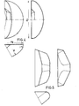
- Preferred embodiments of the cups are each shown in three cracks in FIGS. 4 to 7.
- the generic term used in the description "similar to a basket arch floor” is further illustrated here.
- the cup type according to FIG. 5 is known in its side view as a DIN cup. Further information on usable floors can be found, for example, in the Afflerbach handbook "floors and closures", 1980 edition.
- Bucket elevator belts 27 with vulcanized-on longitudinal profiles 28 are also suitable.
- the transmission takes place by guiding the longitudinal profiles 28 in grooves 29 of the drum 30.
- the cups 31 are fastened here with standard parts on the bucket belt 27.
- a corrugated edge belt 32 with cleats 33 and sheet metal cutting edges 34 attached to this as a tension member is shown in the upper left area of FIG. 8 and in the lower left quadrant of FIG. 9.
- the lateral forces are transmitted from the reinforced belt edges to drum rims 35.
- a cutting head according to FIGS. 10 and 11 is particularly suitable for the most complete discharge possible.
- the drive for the axis of rotation 42 is not shown. It coincides with the axis of the vertical conveyor.
- the tube-like part 40 is connected to the tube part 1 via a ball-turning connection 43.
- Dashed lines indicate (marked by the reference numeral 44) that the inlets 41 are formed in such a way that Approximately, a hemispherical free space is created in which the cups can scoop up to take up food.
- FIG. 12 Another additional device in connection with the continuous conveyor is shown in Fig. 12.
- the continuous conveyor also has a protective shield 6, which is not absolutely necessary, which is placed on the goods 13 and is intended to prevent the beakers from touching the ground (e.g. ship's floor).
- a rake 51 which is inclined with respect to the axis 50 and has the shape of a cone shell is fastened to the lower part 1 of the continuous conveyor by means of a rotary ball connection 52. This device improves the absorption of material because it breaks loose, loosens and causes the material to be conveyed so that higher layers can be removed.
Landscapes
- Engineering & Computer Science (AREA)
- Mechanical Engineering (AREA)
- Ship Loading And Unloading (AREA)
Applications Claiming Priority (2)
| Application Number | Priority Date | Filing Date | Title |
|---|---|---|---|
| DE19843447218 DE3447218A1 (de) | 1984-12-22 | 1984-12-22 | Rohrbecherwerk |
| DE3447218 | 1984-12-22 |
Publications (1)
| Publication Number | Publication Date |
|---|---|
| EP0186772A1 true EP0186772A1 (fr) | 1986-07-09 |
Family
ID=6253769
Family Applications (1)
| Application Number | Title | Priority Date | Filing Date |
|---|---|---|---|
| EP19850114808 Withdrawn EP0186772A1 (fr) | 1984-12-22 | 1985-11-21 | Chaîne transporteuse inclinée pour vrac |
Country Status (2)
| Country | Link |
|---|---|
| EP (1) | EP0186772A1 (fr) |
| DE (1) | DE3447218A1 (fr) |
Cited By (5)
| Publication number | Priority date | Publication date | Assignee | Title |
|---|---|---|---|---|
| EP0307046A1 (fr) * | 1987-09-08 | 1989-03-15 | B.V. Machinefabriek Figee | Dispositif pour décharger de la matière en vrac |
| EP0940358A1 (fr) * | 1998-03-04 | 1999-09-08 | Techint Compagnia Tecnica Internazionale S.P.A. | Convoyeur à godets sans fin, en particulier pour des dispositifs de déchargement de navires ou simulaire |
| RU2286299C2 (ru) * | 2005-02-01 | 2006-10-27 | ФГОУ ВПО "Оренбургский государственный аграрный университет" | Ковшовый элеватор |
| US7631606B2 (en) * | 2005-08-19 | 2009-12-15 | Precision Planting, Inc. | Seed belt for an agricultural planter |
| WO2014005991A1 (fr) * | 2012-07-04 | 2014-01-09 | Aumund Foerdertechnik Gmbh | Élévateur à godets présentant une courroie protégée par ligne de godets |
Families Citing this family (2)
| Publication number | Priority date | Publication date | Assignee | Title |
|---|---|---|---|---|
| DE4229238C2 (de) * | 1991-09-24 | 1996-04-18 | Pwh Anlagen & Systeme Gmbh | Antriebs- und Führungseinrichtung für einen Stetigförderer |
| CN110525726A (zh) * | 2019-08-23 | 2019-12-03 | 天津源天晟科技发展有限公司 | 一种杯子定向装置 |
Citations (3)
| Publication number | Priority date | Publication date | Assignee | Title |
|---|---|---|---|---|
| DE2061492A1 (de) * | 1969-12-15 | 1971-06-24 | Buehler Ag Geb | Elevator, insbesondere fur Senk rechtfbrderung von kornigem oder pul verfbrmigem Fordergut |
| US3861518A (en) * | 1973-10-15 | 1975-01-21 | Borg Warner Ltd | Conveying apparatus |
| AT320521B (de) * | 1972-11-15 | 1975-02-10 | Mut Masch & Transport | Elevator |
-
1984
- 1984-12-22 DE DE19843447218 patent/DE3447218A1/de not_active Withdrawn
-
1985
- 1985-11-21 EP EP19850114808 patent/EP0186772A1/fr not_active Withdrawn
Patent Citations (3)
| Publication number | Priority date | Publication date | Assignee | Title |
|---|---|---|---|---|
| DE2061492A1 (de) * | 1969-12-15 | 1971-06-24 | Buehler Ag Geb | Elevator, insbesondere fur Senk rechtfbrderung von kornigem oder pul verfbrmigem Fordergut |
| AT320521B (de) * | 1972-11-15 | 1975-02-10 | Mut Masch & Transport | Elevator |
| US3861518A (en) * | 1973-10-15 | 1975-01-21 | Borg Warner Ltd | Conveying apparatus |
Cited By (6)
| Publication number | Priority date | Publication date | Assignee | Title |
|---|---|---|---|---|
| EP0307046A1 (fr) * | 1987-09-08 | 1989-03-15 | B.V. Machinefabriek Figee | Dispositif pour décharger de la matière en vrac |
| EP0940358A1 (fr) * | 1998-03-04 | 1999-09-08 | Techint Compagnia Tecnica Internazionale S.P.A. | Convoyeur à godets sans fin, en particulier pour des dispositifs de déchargement de navires ou simulaire |
| RU2286299C2 (ru) * | 2005-02-01 | 2006-10-27 | ФГОУ ВПО "Оренбургский государственный аграрный университет" | Ковшовый элеватор |
| US7631606B2 (en) * | 2005-08-19 | 2009-12-15 | Precision Planting, Inc. | Seed belt for an agricultural planter |
| WO2014005991A1 (fr) * | 2012-07-04 | 2014-01-09 | Aumund Foerdertechnik Gmbh | Élévateur à godets présentant une courroie protégée par ligne de godets |
| US9205988B2 (en) | 2012-07-04 | 2015-12-08 | Aumund Fordertechnik Gmbh | Bucket elevator with belt protected by the bucket section |
Also Published As
| Publication number | Publication date |
|---|---|
| DE3447218A1 (de) | 1986-06-26 |
Similar Documents
| Publication | Publication Date | Title |
|---|---|---|
| DE4125109A1 (de) | Stetigfoerdernder schiffsentlader fuer schuettgueter | |
| DE4429536C2 (de) | Stetigfördernder Schiffsentlader | |
| DE2109213A1 (de) | Förderanlage | |
| DE1481064A1 (de) | Lade- und Transportvorrichtung fuer Schuettgueter | |
| EP0186772A1 (fr) | Chaîne transporteuse inclinée pour vrac | |
| DE3390175C2 (fr) | ||
| EP0170661B1 (fr) | Procede et installation pour decharger des marchandises en vrac d'un gros conteneur | |
| EP0186074A1 (fr) | Le chargement et le transport des matières en vrac à un transporteur vertical par un appareil d'alimentation | |
| DE3612424C2 (fr) | ||
| DE1920874B2 (de) | Schwimmende umladeeinrichtung | |
| DE3490256T1 (de) | Transportsystem | |
| DE2815480C2 (de) | Entladevorrichtung für Schiffe, Bunker, Lagerplätze o.dgl. | |
| EP0741092A2 (fr) | Dispositif de déchargement de navires ou conteneurs similaires pour matières en vrac | |
| DE3041062C2 (de) | Schiffs- und Bunkerentladevorrichtung bzw. Haldenräumvorrichtung, insbesondere zur Förderung schwer fließender Schüttgüter | |
| DE3208228C2 (de) | Einrichtung zum Aufnehmen und Befördern von geschüttetem Haufwerk | |
| DE3130510A1 (de) | "fortlaufend arbeitende loeschvorrichtung fuer schuettgut" | |
| DE10115072C2 (de) | Gutaufnahmeorgan für einen kontinuierlichen Schiffsentlader | |
| DE10115071C2 (de) | Gutaufnahmeorgan für einen kontinuierlichen Schiffsentlader | |
| DE20219176U1 (de) | Schurre zur Gutübergabe von Gutaufnahmeorganen auf einen Senkrechtförderer für einen kontinuierlichen Schiffsentlader | |
| DE3432458A1 (de) | Schiffsentlader | |
| CH251563A (de) | Umladeeinrichtung für Schüttgut. | |
| DE2447600C3 (de) | Verteilanlage für Schüttgut insbesondere zum Entladen von Schiffen | |
| EP0127648A1 (fr) | Convoyeuse a bande pour marchandises en vrac | |
| DE2627013A1 (de) | Selbstentladeschiff | |
| WO1984002323A1 (fr) | Convoyeuse a bande pour le transport incline et vertical de marchandises en vrac |
Legal Events
| Date | Code | Title | Description |
|---|---|---|---|
| PUAI | Public reference made under article 153(3) epc to a published international application that has entered the european phase |
Free format text: ORIGINAL CODE: 0009012 |
|
| AK | Designated contracting states |
Kind code of ref document: A1 Designated state(s): DE FR GB IT NL |
|
| 17P | Request for examination filed |
Effective date: 19861128 |
|
| 17Q | First examination report despatched |
Effective date: 19870722 |
|
| STAA | Information on the status of an ep patent application or granted ep patent |
Free format text: STATUS: THE APPLICATION HAS BEEN WITHDRAWN |
|
| 18W | Application withdrawn |
Withdrawal date: 19891212 |
|
| R18W | Application withdrawn (corrected) |
Effective date: 19891212 |
|
| RIN1 | Information on inventor provided before grant (corrected) |
Inventor name: STENZEL, MANFRED Inventor name: RIECHELMANN, GUNDO, DR. |