EP0186775A2 - Poutre pour coffrages - Google Patents
Poutre pour coffrages Download PDFInfo
- Publication number
- EP0186775A2 EP0186775A2 EP85114881A EP85114881A EP0186775A2 EP 0186775 A2 EP0186775 A2 EP 0186775A2 EP 85114881 A EP85114881 A EP 85114881A EP 85114881 A EP85114881 A EP 85114881A EP 0186775 A2 EP0186775 A2 EP 0186775A2
- Authority
- EP
- European Patent Office
- Prior art keywords
- profile
- girder
- formwork
- support
- contact flange
- Prior art date
- Legal status (The legal status is an assumption and is not a legal conclusion. Google has not performed a legal analysis and makes no representation as to the accuracy of the status listed.)
- Granted
Links
Images
Classifications
-
- E—FIXED CONSTRUCTIONS
- E04—BUILDING
- E04G—SCAFFOLDING; FORMS; SHUTTERING; BUILDING IMPLEMENTS OR AIDS, OR THEIR USE; HANDLING BUILDING MATERIALS ON THE SITE; REPAIRING, BREAKING-UP OR OTHER WORK ON EXISTING BUILDINGS
- E04G11/00—Forms, shutterings, or falsework for making walls, floors, ceilings, or roofs
- E04G11/36—Forms, shutterings, or falsework for making walls, floors, ceilings, or roofs for floors, ceilings, or roofs of plane or curved surfaces end formpanels for floor shutterings
- E04G11/48—Supporting structures for shutterings or frames for floors or roofs
- E04G11/50—Girders, beams, or the like as supporting members for forms
Definitions
- the invention relates to a formwork girder made of a profile girder and an underside belt which can be fastened and tensioned on its underside, which is held at the end regions of the profile girder on anchor shoes which can be connected to the profile girder and is guided over one or more intermediate stamps supported on the profile girder.
- Formwork girders are already known, which consist of parts which can be moved into one another or are displaceable relative to one another, a lower beam being created, for example, by chains.
- the lower flange is fastened here in that the carrier has a large number of transverse bores into which corresponding bolts can be used for hanging the lower flange.
- a stamp is provided, which is supported on the carrier. By means of a corresponding screw sleeve and the rotatability of the stamp, the tensioning belt can be tensioned.
- Such carriers are practically only suitable for use with a lower belt and present a special construction for this purpose.
- the present invention has for its object to provide a formwork girder in which a commercially available profile girder can be used without great design effort, so that, depending on the need and load, the profile girder can be used alone or with a girder belt that can be attached to its underside.
- stamps for the girder belt or several stamps can be used at the desired locations based on the length of the profile beam. Depending on the structural requirements, such a stamp or several stamps can therefore be attached outside the longitudinal center of the profile beam.
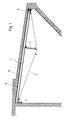
- FIG. 1 shows a section through a rotationally symmetrical building, in the ceiling formwork of which a formwork support according to the invention is used;
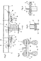
- Fig. 2 is a side view of this formwork beam compared to Figure 1, shown enlarged.
- 3 shows a section along the line I - I in Fig. 2.
- 4 shows a section along the line II - II in FIG. 2 and
- FIG. 5 shows a section along the line III-III in FIG. 2.
- the formwork girder is formed from a profile girder 1 and a beam 2 which can be fastened and tensioned on its underside.
- the profile beam 1 is designed as an I-beam.
- the measures according to the invention can also be applied to profiled beams with a different cross-section, whereby only minor structural preparatory work (additional arrangement of transverse webs, stops, etc.) may be required.
- the lower beam 2 is held at the end regions of the profile beam 1 in anchor shoes 3, which can be connected to the profile beam 1.
- anchor shoes 3 which can be connected to the profile beam 1.
- a stamp 4 is provided approximately in the central region thereof, so that the lower girdle 2 with the profiled beam 1 includes an acute angle that runs to the two ends.
- two can or several such stamps 4 can be arranged on the length of the profile beam.
- the formwork skin 5 is then applied to the side of the profile beam facing away from the beam 2, so that the concrete layer 6 applied thereon is removed.
- the formwork beam can be used to form the formwork beam, a commercially available profile beam, for. B. in the form of an I-beam, so that it can be used for simpler formwork cases and at low loads without additional arrangement of the girder belt. If necessary, a quick assembly of the girder belt is possible.
- the anchor shoes 3 and the plunger 4 are detachably fastened to the I-beam 1 by means of a clamp connection 7 or 8, specifically on the corresponding crossbar 9 of the I-beam 1.
- a clamp connection 7 or 8 specifically on the corresponding crossbar 9 of the I-beam 1.
- the anchor shoes 3 and the plunger 4 have a contact flange 11 or 12 for support on the outer surface 13 of the profile beam 1.
- the width of the contact flange 11 or 12 is greater than the width of the crossbar 9, so that the contact flanges 11 or 12 protrude beyond the crosspiece 9 on both sides.
- clamping jaws 14 and 15 are provided, which overlap the cross bar 9 of the profile beam. These clamping jaws 14, 15 are arranged on both sides of the profile carrier, with screwing being carried out on both sides. Both the contact flanges 11, 12 and the clamping jaws 14, 15 have bores for inserting the clamping screw 16, these clamping screws lying outside the width of the crosspiece 9.
- the thickness of the crossbar 9 of the profile beam 1 is approximately on the outer edge of the contact flange 11 or 12 and / or on the outer edge of the clamping jaws 14, 15 corresponding support bars are provided.
- these support webs 17 are designed as round rods welded to the clamping jaws 15. It is constructive and also easier to handle to attach these support webs to the jaws 15.
- An identical arrangement with support webs is of course also possible with the anchor shoes 3.
- the anchor shoes 3 consist of the contact flange 11 and one or more support parts 18 projecting at right angles to this, wherein on each support part 18 pipe pieces 19 aligned at an acute angle to the plane of the contact flange 11 are arranged. It is useful to weld between the contact flange 11, the supporting parts 18 and the pipe pieces 19. These pipe pieces are used for inserting the beam straps 2 and / or the tendons 20. The ends of the beam strap 2 are therefore held at the appropriate angle that is used when the Stamp 4 and when transferring the same through the lower flange 2 results.
- clamping connections 7 on the anchor shoes 3 are provided on their end region of the contact flange 11 facing away from the stop 10 on the profile rails.
- the clamp connection must ensure proper retention of the anchor shoe 3, whereas the force transmission takes place essentially via the anchor shoes 3 to the stops 10 and thus to the profiled support 1.
- the stamp 4 has a curved support profile 21 with lateral extensions 22, so that the girder straps 2 are not damaged on the one hand in the area of the stamp 4 and on the other hand can not slide off them laterally .
- the girder straps 2 can lie parallel to one another two or more times, or only one such girder strap 2 can be provided.
- a band-shaped profile can be provided or tensioning cables, e.g. B. steel cables od.
- the tendons 20 can be designed in a variety of ways. So it is conceivable to hold the ends of the tendons 2 in a sleeve-shaped part 23 which is provided with an internal thread, so that the part 23 can be screwed onto the threaded bolt 24 for clamping purposes. This threaded bolt 24 is then equipped with a head 25, which is on the back of the tube pieces 19 is introduced.
- profiled tube extensions 26 are provided on the punches, which can be connected to one another via support struts for the purpose of mutual spatial bracing of formwork beams aligned parallel to one another.
- the mutual connection can take place, for example, by means of corresponding double pipe clamps or the like.
- the measures according to the invention can of course be used on a wooden beam which has a corresponding cross-sectional shape.
- stamps 4 of different lengths can be used, which follow one another in ascending and descending height.
- the measures according to the invention bring about a significant improvement in formwork construction, since profiled beams, which are sufficient in normal formwork cases, can also be used as formwork beams with a beam without special construction measures or modifications.
Landscapes
- Engineering & Computer Science (AREA)
- Architecture (AREA)
- Mechanical Engineering (AREA)
- Civil Engineering (AREA)
- Structural Engineering (AREA)
- Forms Removed On Construction Sites Or Auxiliary Members Thereof (AREA)
Applications Claiming Priority (2)
| Application Number | Priority Date | Filing Date | Title |
|---|---|---|---|
| AT0382384A AT390113B (de) | 1984-11-30 | 1984-11-30 | Schalungstraeger |
| AT3823/84 | 1984-11-30 |
Publications (3)
| Publication Number | Publication Date |
|---|---|
| EP0186775A2 true EP0186775A2 (fr) | 1986-07-09 |
| EP0186775A3 EP0186775A3 (en) | 1986-07-16 |
| EP0186775B1 EP0186775B1 (fr) | 1988-05-18 |
Family
ID=3555910
Family Applications (1)
| Application Number | Title | Priority Date | Filing Date |
|---|---|---|---|
| EP19850114881 Expired EP0186775B1 (fr) | 1984-11-30 | 1985-11-23 | Poutre pour coffrages |
Country Status (3)
| Country | Link |
|---|---|
| EP (1) | EP0186775B1 (fr) |
| AT (1) | AT390113B (fr) |
| DE (1) | DE3562789D1 (fr) |
Family Cites Families (3)
| Publication number | Priority date | Publication date | Assignee | Title |
|---|---|---|---|---|
| AT194590B (de) * | 1956-12-13 | 1958-01-10 | Wilhelm Ing Offenbeck | Schalungsträger aus ineinander verschiebbaren oder gegeneinander versetzbaren Teilen |
| AT373020B (de) * | 1982-03-31 | 1983-12-12 | Rauppach Bauges | Ruestungstraeger |
| AT384644B (de) * | 1983-06-07 | 1987-12-10 | Patenver Ag | Traeger mit verstellbarer kruemmung |
-
1984
- 1984-11-30 AT AT0382384A patent/AT390113B/de not_active IP Right Cessation
-
1985
- 1985-11-23 EP EP19850114881 patent/EP0186775B1/fr not_active Expired
- 1985-11-23 DE DE8585114881T patent/DE3562789D1/de not_active Expired
Also Published As
| Publication number | Publication date |
|---|---|
| AT390113B (de) | 1990-03-26 |
| EP0186775A3 (en) | 1986-07-16 |
| EP0186775B1 (fr) | 1988-05-18 |
| DE3562789D1 (en) | 1988-06-23 |
| ATA382384A (de) | 1989-08-15 |
Similar Documents
| Publication | Publication Date | Title |
|---|---|---|
| DE4116439C1 (fr) | ||
| AT390111B (de) | Schalung zur errichtung von baukoerpern aus gussfaehigen materialien, wie beispielsweise beton | |
| DE102014107323A1 (de) | Kranträger für einen Kran, insbesondere für einen Brücken- oder Portalkran, und einen Kran hiermit | |
| DE2058714A1 (de) | Betonrippenplatte | |
| DE2260359C3 (de) | Vorrichtung zur Befestigung von Querriegeln an Gitterträgern | |
| AT500952B1 (de) | Gerüstträger aus aluminium | |
| AT390113B (de) | Schalungstraeger | |
| DE1659218C3 (de) | Verbundfachwerkträger sowie Verfahren zu dessen Montage | |
| DE2206140C3 (de) | Verbundträger | |
| DE8230619U1 (de) | Traegerprofil | |
| DE1941329A1 (de) | Vorrichtung zur Herstellung eines vorgebogenen Traegers | |
| DE1276315B (de) | Profiltraeger, insbesondere fuer Aufzugsgerueste, Seilbahnkabinen od. dgl. | |
| DE2448006A1 (de) | Bruecken-pylon | |
| AT400466B (de) | Vorrichtung zum verbinden von schalungselementen | |
| DE4007948C2 (de) | Vorrichtung zum Verbinden von Schalungselementen | |
| DE3114719C2 (de) | Fachwerkträger | |
| DE3609498A1 (de) | Betonschalung | |
| DE2415856A1 (de) | Keilverbindung fuer schaltafeln o.dgl. | |
| DE19530572A1 (de) | Gebäude-Tragkonstruktion | |
| DE4113150C2 (de) | Verfahren zur Herstellung von Biegeträgern | |
| DE4138003C1 (en) | Joist shuttering for building - has shuttering bearer with head hung in beam support | |
| DE8331076U1 (de) | Vorrichtung zum Verbinden von Schalungselementen | |
| DE3338257C2 (fr) | ||
| DE2145021B2 (de) | Dachbindereinheit für Winterbauhallen | |
| DE2337908A1 (de) | Verschalungseinrichtung |
Legal Events
| Date | Code | Title | Description |
|---|---|---|---|
| PUAI | Public reference made under article 153(3) epc to a published international application that has entered the european phase |
Free format text: ORIGINAL CODE: 0009012 |
|
| PUAL | Search report despatched |
Free format text: ORIGINAL CODE: 0009013 |
|
| AK | Designated contracting states |
Kind code of ref document: A2 Designated state(s): BE CH DE FR GB IT LI LU NL SE |
|
| AK | Designated contracting states |
Kind code of ref document: A3 Designated state(s): BE CH DE FR GB IT LI LU NL SE |
|
| 17P | Request for examination filed |
Effective date: 19860929 |
|
| 17Q | First examination report despatched |
Effective date: 19870812 |
|
| GRAA | (expected) grant |
Free format text: ORIGINAL CODE: 0009210 |
|
| AK | Designated contracting states |
Kind code of ref document: B1 Designated state(s): BE CH DE FR GB IT LI LU NL SE |
|
| PG25 | Lapsed in a contracting state [announced via postgrant information from national office to epo] |
Ref country code: NL Effective date: 19880518 Ref country code: IT Free format text: LAPSE BECAUSE OF FAILURE TO SUBMIT A TRANSLATION OF THE DESCRIPTION OR TO PAY THE FEE WITHIN THE PRESCRIBED TIME-LIMIT;WARNING: LAPSES OF ITALIAN PATENTS WITH EFFECTIVE DATE BEFORE 2007 MAY HAVE OCCURRED AT ANY TIME BEFORE 2007. THE CORRECT EFFECTIVE DATE MAY BE DIFFERENT FROM THE ONE RECORDED. Effective date: 19880518 |
|
| PG25 | Lapsed in a contracting state [announced via postgrant information from national office to epo] |
Ref country code: SE Effective date: 19880531 |
|
| REF | Corresponds to: |
Ref document number: 3562789 Country of ref document: DE Date of ref document: 19880623 |
|
| GBT | Gb: translation of ep patent filed (gb section 77(6)(a)/1977) | ||
| ET | Fr: translation filed | ||
| NLV1 | Nl: lapsed or annulled due to failure to fulfill the requirements of art. 29p and 29m of the patents act | ||
| PG25 | Lapsed in a contracting state [announced via postgrant information from national office to epo] |
Ref country code: LU Free format text: LAPSE BECAUSE OF NON-PAYMENT OF DUE FEES Effective date: 19881130 |
|
| PLBE | No opposition filed within time limit |
Free format text: ORIGINAL CODE: 0009261 |
|
| STAA | Information on the status of an ep patent application or granted ep patent |
Free format text: STATUS: NO OPPOSITION FILED WITHIN TIME LIMIT |
|
| 26N | No opposition filed | ||
| PGFP | Annual fee paid to national office [announced via postgrant information from national office to epo] |
Ref country code: CH Payment date: 19921020 Year of fee payment: 8 |
|
| PGFP | Annual fee paid to national office [announced via postgrant information from national office to epo] |
Ref country code: BE Payment date: 19921027 Year of fee payment: 8 |
|
| PG25 | Lapsed in a contracting state [announced via postgrant information from national office to epo] |
Ref country code: LI Effective date: 19931130 Ref country code: CH Effective date: 19931130 Ref country code: BE Effective date: 19931130 |
|
| BERE | Be: lapsed |
Owner name: RUND-STAHL-BAU G.M.B.H. Effective date: 19931130 |
|
| REG | Reference to a national code |
Ref country code: CH Ref legal event code: PL |
|
| PGFP | Annual fee paid to national office [announced via postgrant information from national office to epo] |
Ref country code: GB Payment date: 19941115 Year of fee payment: 10 |
|
| PGFP | Annual fee paid to national office [announced via postgrant information from national office to epo] |
Ref country code: FR Payment date: 19941130 Year of fee payment: 10 |
|
| PG25 | Lapsed in a contracting state [announced via postgrant information from national office to epo] |
Ref country code: GB Effective date: 19951123 |
|
| GBPC | Gb: european patent ceased through non-payment of renewal fee |
Effective date: 19951123 |
|
| PG25 | Lapsed in a contracting state [announced via postgrant information from national office to epo] |
Ref country code: FR Effective date: 19960731 |
|
| REG | Reference to a national code |
Ref country code: FR Ref legal event code: ST |
|
| PGFP | Annual fee paid to national office [announced via postgrant information from national office to epo] |
Ref country code: DE Payment date: 20010122 Year of fee payment: 16 |
|
| PG25 | Lapsed in a contracting state [announced via postgrant information from national office to epo] |
Ref country code: DE Free format text: LAPSE BECAUSE OF NON-PAYMENT OF DUE FEES Effective date: 20020702 |