EP0186821A1 - Carburateur à venturi variable - Google Patents
Carburateur à venturi variable Download PDFInfo
- Publication number
- EP0186821A1 EP0186821A1 EP85115744A EP85115744A EP0186821A1 EP 0186821 A1 EP0186821 A1 EP 0186821A1 EP 85115744 A EP85115744 A EP 85115744A EP 85115744 A EP85115744 A EP 85115744A EP 0186821 A1 EP0186821 A1 EP 0186821A1
- Authority
- EP
- European Patent Office
- Prior art keywords
- section
- mixing tube
- channel
- rollers
- opposite directions
- Prior art date
- Legal status (The legal status is an assumption and is not a legal conclusion. Google has not performed a legal analysis and makes no representation as to the accuracy of the status listed.)
- Withdrawn
Links
- 230000002093 peripheral effect Effects 0.000 claims description 3
- 239000000203 mixture Substances 0.000 abstract description 4
- 238000002360 preparation method Methods 0.000 abstract description 2
- 239000000446 fuel Substances 0.000 description 4
- 230000015572 biosynthetic process Effects 0.000 description 2
- 230000007423 decrease Effects 0.000 description 1
- 230000003247 decreasing effect Effects 0.000 description 1
Images
Classifications
-
- F—MECHANICAL ENGINEERING; LIGHTING; HEATING; WEAPONS; BLASTING
- F02—COMBUSTION ENGINES; HOT-GAS OR COMBUSTION-PRODUCT ENGINE PLANTS
- F02M—SUPPLYING COMBUSTION ENGINES IN GENERAL WITH COMBUSTIBLE MIXTURES OR CONSTITUENTS THEREOF
- F02M7/00—Carburettors with means for influencing, e.g. enriching or keeping constant, fuel/air ratio of charge under varying conditions
- F02M7/12—Other installations, with moving parts, for influencing fuel/air ratio, e.g. having valves
- F02M7/18—Other installations, with moving parts, for influencing fuel/air ratio, e.g. having valves with means for controlling cross-sectional area of fuel-metering orifice
-
- F—MECHANICAL ENGINEERING; LIGHTING; HEATING; WEAPONS; BLASTING
- F02—COMBUSTION ENGINES; HOT-GAS OR COMBUSTION-PRODUCT ENGINE PLANTS
- F02M—SUPPLYING COMBUSTION ENGINES IN GENERAL WITH COMBUSTIBLE MIXTURES OR CONSTITUENTS THEREOF
- F02M9/00—Carburettors having air or fuel-air mixture passage throttling valves other than of butterfly type; Carburettors having fuel-air mixing chambers of variable shape or position
- F02M9/08—Carburettors having air or fuel-air mixture passage throttling valves other than of butterfly type; Carburettors having fuel-air mixing chambers of variable shape or position having throttling valves rotatably mounted in the passage
-
- F—MECHANICAL ENGINEERING; LIGHTING; HEATING; WEAPONS; BLASTING
- F02—COMBUSTION ENGINES; HOT-GAS OR COMBUSTION-PRODUCT ENGINE PLANTS
- F02M—SUPPLYING COMBUSTION ENGINES IN GENERAL WITH COMBUSTIBLE MIXTURES OR CONSTITUENTS THEREOF
- F02M9/00—Carburettors having air or fuel-air mixture passage throttling valves other than of butterfly type; Carburettors having fuel-air mixing chambers of variable shape or position
- F02M9/10—Carburettors having air or fuel-air mixture passage throttling valves other than of butterfly type; Carburettors having fuel-air mixing chambers of variable shape or position having valves, or like controls, of elastic-wall type for controlling the passage, or for varying cross-sectional area, of fuel-air mixing chambers or of the entry passage
- F02M9/103—Mechanical control
Definitions
- the invention relates to a carburetor with a mixing tube arranged at the narrowest point of a venturi channel, wherein in a plane going approximately through the outlet mouth of the mixing tube and oriented perpendicular to the axis of the venturi channel, two slides can be pivoted in opposite directions to change the flow cross section.
- a carburetor of this type is described in DE-A-2 714 507 and the corresponding US-A-4 206 158.
- the venturi channel has an essentially rectangular cross section. When the slide moves, the ratio of the sides of the rectangle changes very greatly, so that the flow geometry changes greatly.
- the object of the invention is to ensure the same flow geometry and thus constant mixture preparation at all flows.
- rollers which are aligned parallel to one another and are arranged so as to be rotatable in opposite directions to one another, the cylindrical peripheral surfaces of which touch one another and which in each case have a channel with a semicircular cross-section which runs out in the circumferential direction.
- the invention differs from the prior art in that the profiles of the rollers change the flow cross section in each case concentrically to the mouth of the mixing tube. This results in a substantially constant flow geometry at the mouth of the mixing tube, so that a constant mixture formation is ensured.
- a circular flow cross-section is ensured in that the channel has a segment with a semi-circular one Cross section and with a crescent-shaped, tapering in the circumferential direction.
- the cross section essentially retains the circular shape and only changes to the similar elliptical shape.
- rollers carry meshing gears.
- a metering of the fuel supply in accordance with the flow cross-section is ensured in that the mixing tube opens into the circumferential surface of an actuating chamber in which a rotatable actuating piston with an inclined head surface is arranged, which, when it rotates, blocks the outlet opening of the mixing tube.
- the fuel supply is coupled to the flow cross section in that a spur gear seated on the actuating piston engages with the gear wheel of a roller.
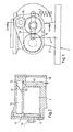
- the carburetor 1 is a so-called venturi gasifier with a venturi channel 2 and a mixing tube 3 opening coaxially into the venturi channel.
- a venturi gasifier with a venturi channel 2 and a mixing tube 3 opening coaxially into the venturi channel.
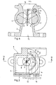
- two rollers 4 are rotatably arranged parallel to one another , which engage with each other with gear wheels 5, so that the rollers 4 can rotate in opposite directions relative to the engagement of the gear wheels 5.
- a roller 4 is coupled via a radial arm 19 to a tension element 6 of a throttle cable and a return spring 7. According to the actuation of the tension element 6, the rollers 4 are pivoted in opposite directions to one another.
- the rollers 4 have channels 8 which are aligned symmetrically to one another.
- Each trough 8 is a segment cutout with a semicircular cross section, the trough being aligned perpendicular to the axis of the relevant roller 4 according to Q e.
- Each trough 8 ends at one end in the circumferential direction in a sickle-shaped section 9.
- the channels 8 in the orientation shown in FIG. 4 form a channel with a circular cross-section in the extension of the inlet funnel 10 of the venturi channel 2.
- the mixing tube 3 opens centrally within this channel.
- the DJf connects to the channel in the usual way fusor 11. 3 and 4, the position of the rollers for the largest flow cross-section and in dash-dotted lines for the smallest flow cross-section is indicated in solid lines.
- the rollers 4 are pivoted against each other.
- the flow cross section of the carburetor is largest and circular. If the tension element 6 is not actuated, the return spring 7 becomes effective.
- Corresponding to the rotation of the rollers there is an oval-shaped, decreasing cross-section in which the mixing tube lies centrally.
- the tapering sections 9 of the channel 8 again ensure a circular cross-section with the smallest flow cross-section, as indicated by dash-dotted lines.
- the cross-section of the central channel continuously decreases in accordance with the rotation of the rollers.
- the cross section is always centered around the mouth of the mixing tube 3. As a result, the flow conditions and thus the mixture formation are always the same.
- the mixing tube 3 is connected to an outlet opening 12 in the peripheral wall of an actuating chamber 13.
- An actuating piston 14 is rotatably arranged within the actuating chamber 13 and has a bevelled head surface 15.
- the actuating piston 14 carries at the end a spur gear 16 which meshes with a gear 5 of a roller 4 so that the actuating piston 14 is pivoted synchronously with the rotation of the rollers 4.
- a tube 17 extends into the actuating chamber 13, which plunges into a float chamber 18 and through which the fuel flows.
- the outlet opening 12 is partially opened and closed in accordance with the rotation of the rollers 4 and the rotation of the actuating piston 14, so that the fuel supply is metered in accordance with the effective opening of the venturi channel 2.
Landscapes
- Engineering & Computer Science (AREA)
- Chemical & Material Sciences (AREA)
- Combustion & Propulsion (AREA)
- Mechanical Engineering (AREA)
- General Engineering & Computer Science (AREA)
- Catching Or Destruction (AREA)
- Output Control And Ontrol Of Special Type Engine (AREA)
- Disintegrating Or Milling (AREA)
- Transition And Organic Metals Composition Catalysts For Addition Polymerization (AREA)
- Acyclic And Carbocyclic Compounds In Medicinal Compositions (AREA)
Applications Claiming Priority (2)
| Application Number | Priority Date | Filing Date | Title |
|---|---|---|---|
| DE19843445841 DE3445841A1 (de) | 1984-12-15 | 1984-12-15 | Venturivergaser |
| DE3445841 | 1984-12-15 |
Publications (1)
| Publication Number | Publication Date |
|---|---|
| EP0186821A1 true EP0186821A1 (fr) | 1986-07-09 |
Family
ID=6252892
Family Applications (1)
| Application Number | Title | Priority Date | Filing Date |
|---|---|---|---|
| EP85115744A Withdrawn EP0186821A1 (fr) | 1984-12-15 | 1985-12-11 | Carburateur à venturi variable |
Country Status (3)
| Country | Link |
|---|---|
| EP (1) | EP0186821A1 (fr) |
| JP (1) | JPS62129555A (fr) |
| DE (1) | DE3445841A1 (fr) |
Cited By (1)
| Publication number | Priority date | Publication date | Assignee | Title |
|---|---|---|---|---|
| US7102078B2 (en) | 2004-06-24 | 2006-09-05 | I F M Electronic Gmbh | Housing for holding electrical and/or electronic components |
Citations (3)
| Publication number | Priority date | Publication date | Assignee | Title |
|---|---|---|---|---|
| FR547335A (fr) * | 1922-02-16 | 1922-12-07 | Carburateur à diffuseur extensible | |
| GB621142A (en) * | 1946-07-09 | 1949-04-05 | John Percival Beeston | Improvements in or relating to valves |
| DE2049765A1 (de) * | 1969-10-10 | 1971-04-22 | Kendig, Willard Zareh, Yettem, CaUf(VStA) | Kraftstoff Dosiervorrichtung fur Brennkraftmaschinen |
Family Cites Families (6)
| Publication number | Priority date | Publication date | Assignee | Title |
|---|---|---|---|---|
| CA1013223A (en) * | 1973-07-30 | 1977-07-05 | Dresser Industries | Fuel introduction device for internal combustion engine |
| GB1502984A (en) * | 1975-03-14 | 1978-03-08 | Ford Motor Co | Variable venturi carburettor |
| US4206158A (en) * | 1976-04-05 | 1980-06-03 | Ford Motor Company | Sonic flow carburetor with fuel distributing means |
| US4231971A (en) * | 1979-04-11 | 1980-11-04 | Dresser Industries, Inc. | Flow method and device |
| US4305892A (en) * | 1979-08-08 | 1981-12-15 | Borg-Warner Corporation | Carburetor |
| DE3200744A1 (de) * | 1982-01-13 | 1983-07-21 | Werner Karl-Heinz 2000 Hamburg Hintze | Vergaserdiffusor aus nicht starrem material, fuer ottomotoren |
-
1984
- 1984-12-15 DE DE19843445841 patent/DE3445841A1/de not_active Withdrawn
-
1985
- 1985-12-11 EP EP85115744A patent/EP0186821A1/fr not_active Withdrawn
- 1985-12-16 JP JP28271385A patent/JPS62129555A/ja active Pending
Patent Citations (3)
| Publication number | Priority date | Publication date | Assignee | Title |
|---|---|---|---|---|
| FR547335A (fr) * | 1922-02-16 | 1922-12-07 | Carburateur à diffuseur extensible | |
| GB621142A (en) * | 1946-07-09 | 1949-04-05 | John Percival Beeston | Improvements in or relating to valves |
| DE2049765A1 (de) * | 1969-10-10 | 1971-04-22 | Kendig, Willard Zareh, Yettem, CaUf(VStA) | Kraftstoff Dosiervorrichtung fur Brennkraftmaschinen |
Cited By (1)
| Publication number | Priority date | Publication date | Assignee | Title |
|---|---|---|---|---|
| US7102078B2 (en) | 2004-06-24 | 2006-09-05 | I F M Electronic Gmbh | Housing for holding electrical and/or electronic components |
Also Published As
| Publication number | Publication date |
|---|---|
| JPS62129555A (ja) | 1987-06-11 |
| DE3445841A1 (de) | 1986-06-19 |
Similar Documents
| Publication | Publication Date | Title |
|---|---|---|
| DE2560225C2 (de) | Prüfstandsvorrichtung zum Einstellen der Drosselklappe von Vergasern | |
| DE2348045B2 (de) | Vergaser für Brennkraftmaschinen | |
| EP0186821A1 (fr) | Carburateur à venturi variable | |
| DE2451378C3 (de) | Vergaser für Brennkraftmaschinen | |
| DD232474A5 (de) | Vorrichtung zur verteilung eines flusses eines granulatfoermigen materials | |
| DE3120637A1 (de) | Vorrichtung zur mengen- und/oder verhaeltnisregelung von zwei gas- und/oder fluessigkeitsstroemen | |
| DE818593C (de) | Mischer fuer Luft und Gas zum Betrieb von insbesondere mit Generatorgas betriebenen Kraftfahrzeug-Brennkraftmaschinen | |
| DE2810177A1 (de) | Kraftstoff-zumess-ventil einer kraftstoff-einspritzanlage | |
| EP0515965B1 (fr) | Soupape de contrôle ou de réglage du débit de fluide | |
| DE3526608A1 (de) | Vorrichtung zur regelung der menge und/oder des mischungsverhaeltnisses eines brenngas-luft-gemisches | |
| DE2737307C2 (de) | Vorrichtung zur steuerbaren Zuführung von Kalt- und Warmluft zum Luftfilter einer Verbrennungskraftmaschine | |
| DE2459406C2 (de) | Vergaser für Verbrennungskraftmaschinen | |
| DE3028852C2 (de) | Vergaser für Brennkraftmaschinen | |
| DE2432675B2 (de) | Regelventil | |
| DE2461354A1 (de) | Vergaser | |
| DE69201109T2 (de) | Drosselklappenstutzen für eine Brennstoffzufuhrvorrichtung für Brennkraftmaschine. | |
| DE4135806A1 (de) | Durchstroemkoerper mit einer drosseleinrichtung fuer eine kraftstoffversorgungsanlage eines motors mit interner verbrennung | |
| DE464131C (de) | Spritzvergaser mit Hauptluftschieber und einem mit diesem gekuppelten Brennstoffschieber | |
| DE2228167C3 (de) | Registervergaser für Verbrennungsmotoren | |
| DE2701906C2 (de) | Vergaser für Verbrennungskraftmaschinen | |
| DE188350C (fr) | ||
| DE274185C (fr) | ||
| DE265344C (fr) | ||
| DE3149277C1 (de) | Fallstromvergaser mit veraenderlichem Venturiquerschnitt fuer Brennkraftmaschinen | |
| DE672419C (de) | Vergaser mit einem Hauptmischraum und einem mit diesem verbundenen, zur Erzeugung eines ueberriechen Gemisches dienenden Hilfsmischraum |
Legal Events
| Date | Code | Title | Description |
|---|---|---|---|
| PUAI | Public reference made under article 153(3) epc to a published international application that has entered the european phase |
Free format text: ORIGINAL CODE: 0009012 |
|
| AK | Designated contracting states |
Kind code of ref document: A1 Designated state(s): AT BE CH DE FR GB IT LI NL SE |
|
| STAA | Information on the status of an ep patent application or granted ep patent |
Free format text: STATUS: THE APPLICATION IS DEEMED TO BE WITHDRAWN |
|
| 18D | Application deemed to be withdrawn |
Effective date: 19870309 |
|
| RIN1 | Information on inventor provided before grant (corrected) |
Inventor name: KLEIN, BERNHARD |