EP0186824A1 - Bobine pour pellicule photographique - Google Patents
Bobine pour pellicule photographique Download PDFInfo
- Publication number
- EP0186824A1 EP0186824A1 EP85115781A EP85115781A EP0186824A1 EP 0186824 A1 EP0186824 A1 EP 0186824A1 EP 85115781 A EP85115781 A EP 85115781A EP 85115781 A EP85115781 A EP 85115781A EP 0186824 A1 EP0186824 A1 EP 0186824A1
- Authority
- EP
- European Patent Office
- Prior art keywords
- coil
- spool
- film
- slot
- core
- Prior art date
- Legal status (The legal status is an assumption and is not a legal conclusion. Google has not performed a legal analysis and makes no representation as to the accuracy of the status listed.)
- Granted
Links
- 230000007704 transition Effects 0.000 claims abstract description 19
- 238000003780 insertion Methods 0.000 claims description 10
- 230000037431 insertion Effects 0.000 claims description 10
- 238000000034 method Methods 0.000 description 8
- 238000012545 processing Methods 0.000 description 7
- 238000002347 injection Methods 0.000 description 3
- 239000007924 injection Substances 0.000 description 3
- 230000003068 static effect Effects 0.000 description 3
- 238000004804 winding Methods 0.000 description 3
- 238000004026 adhesive bonding Methods 0.000 description 2
- 230000015572 biosynthetic process Effects 0.000 description 1
- 238000013461 design Methods 0.000 description 1
- 238000011161 development Methods 0.000 description 1
- 230000000694 effects Effects 0.000 description 1
- 238000005516 engineering process Methods 0.000 description 1
- 230000002349 favourable effect Effects 0.000 description 1
- 239000000463 material Substances 0.000 description 1
- 239000000203 mixture Substances 0.000 description 1
- 238000004806 packaging method and process Methods 0.000 description 1
Images

Classifications
-
- G—PHYSICS
- G03—PHOTOGRAPHY; CINEMATOGRAPHY; ANALOGOUS TECHNIQUES USING WAVES OTHER THAN OPTICAL WAVES; ELECTROGRAPHY; HOLOGRAPHY
- G03B—APPARATUS OR ARRANGEMENTS FOR TAKING PHOTOGRAPHS OR FOR PROJECTING OR VIEWING THEM; APPARATUS OR ARRANGEMENTS EMPLOYING ANALOGOUS TECHNIQUES USING WAVES OTHER THAN OPTICAL WAVES; ACCESSORIES THEREFOR
- G03B17/00—Details of cameras or camera bodies; Accessories therefor
- G03B17/28—Locating light-sensitive material within camera
- G03B17/30—Locating spools or other rotatable holders of coiled film
-
- G—PHYSICS
- G03—PHOTOGRAPHY; CINEMATOGRAPHY; ANALOGOUS TECHNIQUES USING WAVES OTHER THAN OPTICAL WAVES; ELECTROGRAPHY; HOLOGRAPHY
- G03B—APPARATUS OR ARRANGEMENTS FOR TAKING PHOTOGRAPHS OR FOR PROJECTING OR VIEWING THEM; APPARATUS OR ARRANGEMENTS EMPLOYING ANALOGOUS TECHNIQUES USING WAVES OTHER THAN OPTICAL WAVES; ACCESSORIES THEREFOR
- G03B2217/00—Details of cameras or camera bodies; Accessories therefor
- G03B2217/26—Holders for containing light-sensitive material and adapted to be inserted within the camera
- G03B2217/261—Details of spools
Definitions
- the invention relates to a spool for tape-shaped recording media, in particular for photographic films, with a slot arranged in the spool core and means provided therein for fastening the end of the tape inserted into the slot, with an insert approximately between the axially extending upper and lower slot surfaces and the outer surfaces of the spool core rounded transition surfaces are provided.
- Such a coil is known from DE-AS 10 58 363.
- the transition surfaces adjoining the slot walls are very strongly curved and extend in cross section only over an angular range of approximately 90 °, with kinks being accepted between these transition surfaces and the outer surfaces of the coil core.
- films which have been wound onto such film spools often do not withstand higher tensile loads when they are unwound.
- films which are given to the processing facilities set up for this purpose after the image-wise exposure by the user for development and copying are machine-wound in the so-called presplicer devices after the mechanical removal of the film roll including the spool core from the film cassette and for the purposes of continuous throughput processing long tapes glued together, with the beginning of a film being glued to the end of a preceding film.
- the film is also unwound from the supply reel at high speed.
- the film is also subjected to a high static load at the end of the unwinding process in the camera and in the presplicer device, because the film does not come to rest on the insertion-side surfaces of the spool slot or at most on an edge of the film slot. If the film is supported at all, it is only limited to edge contact.
- the present invention has for its object to provide a film reel, when using the film withstands the aforementioned dynamic tensile loads and the static holding forces are increased.
- the film should not only be prevented from being torn out of the fastening on the spool side, but also from being torn off in the end region of the film in front of the fastening point.
- the inventive design of the spool ensures that the film does not receive any formation characterized by extreme curvatures or kinks, even if it is stored for a long time in the wound state in the end region coming into contact with the spool core mix tensile load of the film would reduce in this area.
- This advantage can also be achieved with the film spool according to the invention if the film is rewound by the user in a direction opposite to the original winding direction after the image-wise exposure during the return transport into the film cassette.
- the film is supported in an extremely favorable manner when the unwinding process is abruptly ended by the film spool designed according to the invention, so that tearing off of the film end is avoided despite high tensile load.
- the static holding forces are also improved, since at the end of an unwinding process in the camera or in the Spresplicer device, even when the spool is swinging into an end position, the film is in flat contact with the transition surfaces of the spool core.
- the spool according to the invention is not only advantageous in connection with photographic films, but is also suitable for other recording media, e.g. for magnetic tapes.
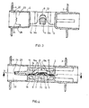
- the film spool 1 injection molded from plastic has an essentially cylindrical spool core 2 with two lateral flanges 3 and 4.
- a slot 5 which runs axially through the center of the core and which is used for inserting and fastening the end piece of a photographic roll film, not shown, e.g. of a 35 mm film, which is wound up after the attachment to the film spool, for which purpose the film end in FIG. 2 is inserted from the right into the spool slot 5 and after the attachment of the film in this slot the film spool 1 in the illustration in FIG. 2 is turned clockwise.
- a photographic roll film not shown, e.g. of a 35 mm film
- the film hook 7 serving for film fastening is injection molded, which has a hook shaft 8 and a hook head 9.
- the hook shaft 8 has a ramp 9 on the side of the film insert, on which the end of the film to be inserted can slide during the insertion movement until after the insertion movement continues it falls over the hook 7 with a fastening hole designed as an elongated hole and after slightly pulling back the film, it Gap 10 between the hook head 9 and the Diaphragm wall 6 hooked.
- akenschaft in its base 11 the shape of the elongated hole of the film 8, so that the edges of the film can create enough in the slot to the hook leg. 11
- two hold-downs 13, 14 are molded, which also have ramps 15 on the side of the film insert, which are chamfered towards the hook head 9 (surfaces 13a, 14a).
- the hold-downs 13, 14 have the effect that the lateral edges of the film end are arched downwards when inserted into the slot 5 when the film end is pressed upwards in the longitudinal axis of the film as it slides onto the ramp 9 of the film hook 7.
- the hold-down devices 13, 14 then prevent the film with its elongated hole from the locking hook 7 from lifting out again.
- the ramp 9 on the hook 7 and the ramps 15 on the hold-down devices 13, 14 allow an effortless insertion of the film end into the slot 5 without the film being compressed.
- the aforementioned ramps are made relatively flat. They enclose an angle of approximately 60 °, which is approximately symmetrical to the coil center plane M shown in FIG. 2.
- Fig. 2 it can also be seen that the recess 10 located between the hook head 9 and the diaphragm wall 6, in which the film is caught, is arranged below the coil center plane, ie on the side above which the winding takes place during assembly.
- the recess 10 only slightly exceeds the film thickness in its clear width.
- Transition surfaces 16, 17 adjoin the walls 6, 12 of the coil slot 5, which in turn merge into the outer surfaces of the coil core 2. There is no kink in the direction of the slot surfaces 6, 12 or in the direction of the cylindrical outer surfaces of the coil core 2.
- the cross-sectional areas 16, 17 each extend in cross-section according to FIG. 2 over an angular range of approximately 135 ° and form within this area lateral surfaces of circular cylinders with a radius which in the exemplary embodiment according to FIG. 2 is approximately 0.38 times the radius the cylindrical outer surface of the coil core 2.
- This configuration ensures that the transition surfaces 16, 17 receive the largest possible radius without there being more or less sharp bends or strong curvatures following the slot surfaces 6, 12 or following the outer contour of the coil core 2. Rather, the curvature in the transition from the flat slot walls 6, 12 to the cylindrical outer surfaces of the coil core 2 is almost constant and as small as possible.
- the film lies snugly against either the transition surface 16 or the transition surface 17 and assumes only the minimal curvature as determined by the curvature of the transition surface 16 or 17.
- the winding should preferably take place over the transition surface 16. Even if the film assumes this predetermined curvature irreversibly when stored for a long time in the wound state, it is not so large that during the mechanical unwinding when the film jerkily stops the tensile strength of the film is overstressed.
- the film reel reaches an angular position at the end of the unwinding process under the action of the film pull, in which the film lies flat against the transition surface 16 serving as a shoulder .
- the film spool 1 has further slots 18, 19 between the spool slot 5 and the outer surfaces of the spool core 2 for reasons of material savings and for reasons of injection technology, the opening of which lies on the outside opposite to the film insertion side.
- the slots 18, 19 also extend parallel to the central axis of the film spool and are divided in the middle by transverse webs 20, 21. These crosspieces prevent that when storing and transporting the empty film reels as loose bulk goods before the side flanges 3 and 4 of a coil get caught in the slots 18 and 19 of other coils.
- the coil core 2 continues into a hub part 22, in which a driver web 23 is arranged.
- This web can be used to drive the spool in the camera or in processing devices from camera or device-side film spool keys, whereby the drive movement is transferred from the camera or assembly or processing machine to the film spool.
- the camera or machine-side drive key can be easily detached from the carrier web 23, it is trapezoidal in longitudinal section, as can be seen from FIG. 4.
- the free edge 24 of the carrier web 23 has a recess 25, which is arranged at one end of the web, as an identifier for the angular positioning of the coil.
- This eccentric arrangement which is asymmetrical with respect to the spool axis, allows the film spool to be positioned in the camera or assembly or processing machine in an angular manner with a correspondingly asymmetrical drive key by scanning the identifier. This is necessary, for example, in order to precisely contrast the slot opening on the insertion side with the film transport channel of the packaging machine when the film end is being mechanically pushed into the spool slot 5 of the film spool 1.
Landscapes
- Physics & Mathematics (AREA)
- General Physics & Mathematics (AREA)
- Storage Of Web-Like Or Filamentary Materials (AREA)
- Details Of Cameras Including Film Mechanisms (AREA)
Applications Claiming Priority (2)
| Application Number | Priority Date | Filing Date | Title |
|---|---|---|---|
| DE19843447215 DE3447215A1 (de) | 1984-12-22 | 1984-12-22 | Spule fuer bandfoermige aufzeichnungstraeger, insbesondere fuer fotografische filme |
| DE3447215 | 1984-12-22 |
Publications (2)
| Publication Number | Publication Date |
|---|---|
| EP0186824A1 true EP0186824A1 (fr) | 1986-07-09 |
| EP0186824B1 EP0186824B1 (fr) | 1988-06-22 |
Family
ID=6253768
Family Applications (1)
| Application Number | Title | Priority Date | Filing Date |
|---|---|---|---|
| EP85115781A Expired EP0186824B1 (fr) | 1984-12-22 | 1985-12-11 | Bobine pour pellicule photographique |
Country Status (4)
| Country | Link |
|---|---|
| US (1) | US4984751A (fr) |
| EP (1) | EP0186824B1 (fr) |
| JP (1) | JPS61156033A (fr) |
| DE (2) | DE3447215A1 (fr) |
Cited By (6)
| Publication number | Priority date | Publication date | Assignee | Title |
|---|---|---|---|---|
| GB2199805A (en) * | 1987-01-20 | 1988-07-20 | Konishiroku Photo Ind | Photographic film spool |
| EP0342372A3 (en) * | 1988-05-19 | 1990-07-25 | Minnesota Mining And Manufacturing Company | Spool, cartridge and method for fastening a photographic film |
| EP0414150A3 (en) * | 1989-08-21 | 1992-05-06 | Eastman Kodak Company | Spool for photographic film or other web material |
| EP0467154A3 (en) * | 1990-07-17 | 1992-08-05 | Agfa-Gevaert Ag | Spool for an information carrier tape, especially for photographic films |
| US5295635A (en) * | 1992-08-28 | 1994-03-22 | Eastman Kodak Company | Spool to film attachment |
| US5295634A (en) * | 1991-11-18 | 1994-03-22 | Eastman Kodak Company | Film cassette with spool core having fastening hook |
Families Citing this family (5)
| Publication number | Priority date | Publication date | Assignee | Title |
|---|---|---|---|---|
| US5499781A (en) * | 1994-01-14 | 1996-03-19 | Eastman Kodak Company | Film spool with axially flexible core to engage and release film end |
| US5449125A (en) * | 1994-01-14 | 1995-09-12 | Eastman Kodak Company | Film spool with internal flexures to engage and release film end |
| US5445343A (en) * | 1994-01-14 | 1995-08-29 | Eastman Kodak Company | Film spool with integral cantilever to engage and release film end |
| JP3530258B2 (ja) * | 1995-03-24 | 2004-05-24 | 富士写真フイルム株式会社 | フイルム巻き取り軸 |
| DE69621158T2 (de) * | 1995-09-13 | 2002-09-05 | Fuji Photo Film Co. Ltd., Minamiashigara | Fotografische Filmrolle |
Citations (4)
| Publication number | Priority date | Publication date | Assignee | Title |
|---|---|---|---|---|
| US2477010A (en) * | 1946-12-21 | 1949-07-26 | Du Pont | Spool |
| DE1058363B (de) * | 1956-07-05 | 1959-05-27 | Gevaert Photo Prod Nv | Kleinbildfilmspule |
| US3361380A (en) * | 1966-01-25 | 1968-01-02 | Fuji Photo Film Co Ltd | Spool for photographic film |
| EP0077972A1 (fr) * | 1981-10-24 | 1983-05-04 | Agfa-Gevaert AG | Bobine à serrer pourvue d'une dent d'attache |
Family Cites Families (8)
| Publication number | Priority date | Publication date | Assignee | Title |
|---|---|---|---|---|
| US1930144A (en) * | 1932-11-16 | 1933-10-10 | Eastman Kodak Co | Photographic film spool |
| GB834693A (en) * | 1956-07-05 | 1960-05-11 | Gevaert Photo Production N V | Improvements in or relating to film spools |
| DE1522153B1 (de) * | 1967-02-11 | 1969-09-18 | Kodak Sa | Filmspule, vorzugsweise mehrteilige Aufwickelspule für photographische oder kinematographische Kamera |
| US3982709A (en) * | 1975-08-18 | 1976-09-28 | Bell & Howell Company | Film core with restrainer |
| US3973740A (en) * | 1975-10-07 | 1976-08-10 | Microfilm Enterprises Corporation | Film reel spacer |
| JPS56144418A (en) * | 1980-04-11 | 1981-11-10 | Minolta Camera Co Ltd | Film winding spool of camera |
| US4384687A (en) * | 1981-04-27 | 1983-05-24 | Western Electric Company, Inc. | Winding arbor with quick release facilities |
| DE8131086U1 (de) * | 1981-10-24 | 1982-03-25 | Agfa-Gevaert Ag, 5090 Leverkusen | Doppelhakenspule |
-
1984
- 1984-12-22 DE DE19843447215 patent/DE3447215A1/de active Granted
-
1985
- 1985-12-11 EP EP85115781A patent/EP0186824B1/fr not_active Expired
- 1985-12-11 DE DE8585115781T patent/DE3563484D1/de not_active Expired
- 1985-12-13 US US06/808,494 patent/US4984751A/en not_active Expired - Fee Related
- 1985-12-19 JP JP60284473A patent/JPS61156033A/ja active Granted
Patent Citations (4)
| Publication number | Priority date | Publication date | Assignee | Title |
|---|---|---|---|---|
| US2477010A (en) * | 1946-12-21 | 1949-07-26 | Du Pont | Spool |
| DE1058363B (de) * | 1956-07-05 | 1959-05-27 | Gevaert Photo Prod Nv | Kleinbildfilmspule |
| US3361380A (en) * | 1966-01-25 | 1968-01-02 | Fuji Photo Film Co Ltd | Spool for photographic film |
| EP0077972A1 (fr) * | 1981-10-24 | 1983-05-04 | Agfa-Gevaert AG | Bobine à serrer pourvue d'une dent d'attache |
Cited By (8)
| Publication number | Priority date | Publication date | Assignee | Title |
|---|---|---|---|---|
| GB2199805A (en) * | 1987-01-20 | 1988-07-20 | Konishiroku Photo Ind | Photographic film spool |
| DE3801571A1 (de) * | 1987-01-20 | 1988-08-04 | Konishiroku Photo Ind | Spule fuer photographischen rollfilm |
| GB2199805B (en) * | 1987-01-20 | 1991-09-25 | Konishiroku Photo Ind | Photographic film spool |
| EP0342372A3 (en) * | 1988-05-19 | 1990-07-25 | Minnesota Mining And Manufacturing Company | Spool, cartridge and method for fastening a photographic film |
| EP0414150A3 (en) * | 1989-08-21 | 1992-05-06 | Eastman Kodak Company | Spool for photographic film or other web material |
| EP0467154A3 (en) * | 1990-07-17 | 1992-08-05 | Agfa-Gevaert Ag | Spool for an information carrier tape, especially for photographic films |
| US5295634A (en) * | 1991-11-18 | 1994-03-22 | Eastman Kodak Company | Film cassette with spool core having fastening hook |
| US5295635A (en) * | 1992-08-28 | 1994-03-22 | Eastman Kodak Company | Spool to film attachment |
Also Published As
| Publication number | Publication date |
|---|---|
| DE3563484D1 (en) | 1988-07-28 |
| US4984751A (en) | 1991-01-15 |
| DE3447215C2 (fr) | 1988-05-11 |
| JPS61156033A (ja) | 1986-07-15 |
| JPH0567007B2 (fr) | 1993-09-24 |
| DE3447215A1 (de) | 1986-09-18 |
| EP0186824B1 (fr) | 1988-06-22 |
Similar Documents
| Publication | Publication Date | Title |
|---|---|---|
| DE68915080T2 (de) | Spule für Bandfilme. | |
| DE2557519C3 (de) | Bandkassette mit Bandspulen-Bremsvorrichtung | |
| EP0186824B1 (fr) | Bobine pour pellicule photographique | |
| EP0045428B1 (fr) | Crochet et bobine autopreneuse pour l'enroulement et le déroulement rotatifs | |
| DE8131086U1 (de) | Doppelhakenspule | |
| DE2136913B2 (de) | Bandkassette | |
| DE1260812B (de) | Verfahren zum Wiederaufbringen von unbeabsichtigt, vom Wickel einer Endlos-Bandspulein einer Kassette, abgeglittenem Band und Kassette hierfuer | |
| DE1955102C3 (de) | Vorspannband für ein bandförmiges Aufzeichnungsmedium | |
| DE2943488A1 (de) | Aufwickeleinrichtung fuer bandfoermiges material | |
| DE2255749C3 (de) | Filmkassette | |
| DE2637016C2 (fr) | ||
| DE1177894B (de) | Wickelkern mit zylindrischer Oberflaeche und Vorrichtung zum Herstellen desselben | |
| DE2135196C3 (de) | Bandkassette | |
| DE69008074T2 (de) | Spule für photographischen Film oder andere bahnförmige Materialien. | |
| EP0077972B1 (fr) | Bobine à serrer pourvue d'une dent d'attache | |
| EP0293993A2 (fr) | Axe de bobinage pour bande | |
| DE69116043T2 (de) | Bandspule für eine kassette | |
| CH649405A5 (de) | Magnetbandkassette. | |
| DE2530817A1 (de) | Selbsteinfaedelungsvorspann fuer bandwickel und bandwickel mit solchen vorspanns | |
| DE3406803A1 (de) | Farbbandcassette | |
| DE2105008A1 (de) | Kassette für streifenförmiges Material | |
| DE69013820T2 (de) | Bandkassette. | |
| EP0467154A2 (fr) | Bobine pour support d'enregistrement en forme de bande, en particulier pour des films photographiques | |
| DE2444106A1 (de) | Filmspule fuer fotografischen rollfilm | |
| DE2804136C2 (de) | Kassette |
Legal Events
| Date | Code | Title | Description |
|---|---|---|---|
| PUAI | Public reference made under article 153(3) epc to a published international application that has entered the european phase |
Free format text: ORIGINAL CODE: 0009012 |
|
| 17P | Request for examination filed |
Effective date: 19851211 |
|
| AK | Designated contracting states |
Kind code of ref document: A1 Designated state(s): BE CH DE FR GB IT LI |
|
| RAP1 | Party data changed (applicant data changed or rights of an application transferred) |
Owner name: AGFA-GEVAERT AG |
|
| 17Q | First examination report despatched |
Effective date: 19870616 |
|
| GRAA | (expected) grant |
Free format text: ORIGINAL CODE: 0009210 |
|
| AK | Designated contracting states |
Kind code of ref document: B1 Designated state(s): BE CH DE FR GB IT LI |
|
| ITF | It: translation for a ep patent filed | ||
| REF | Corresponds to: |
Ref document number: 3563484 Country of ref document: DE Date of ref document: 19880728 |
|
| GBT | Gb: translation of ep patent filed (gb section 77(6)(a)/1977) | ||
| ET | Fr: translation filed | ||
| PLBI | Opposition filed |
Free format text: ORIGINAL CODE: 0009260 |
|
| 26 | Opposition filed |
Opponent name: EASTMAN KODAK COMPANY Effective date: 19890322 |
|
| PLBN | Opposition rejected |
Free format text: ORIGINAL CODE: 0009273 |
|
| STAA | Information on the status of an ep patent application or granted ep patent |
Free format text: STATUS: OPPOSITION REJECTED |
|
| ITTA | It: last paid annual fee | ||
| 27O | Opposition rejected |
Effective date: 19901010 |
|
| PGFP | Annual fee paid to national office [announced via postgrant information from national office to epo] |
Ref country code: CH Payment date: 19941118 Year of fee payment: 10 |
|
| PGFP | Annual fee paid to national office [announced via postgrant information from national office to epo] |
Ref country code: BE Payment date: 19941214 Year of fee payment: 10 |
|
| PG25 | Lapsed in a contracting state [announced via postgrant information from national office to epo] |
Ref country code: LI Effective date: 19951231 Ref country code: CH Effective date: 19951231 Ref country code: BE Effective date: 19951231 |
|
| BERE | Be: lapsed |
Owner name: AGFA-GEVAERT A.G. Effective date: 19951231 |
|
| REG | Reference to a national code |
Ref country code: CH Ref legal event code: PL |
|
| REG | Reference to a national code |
Ref country code: GB Ref legal event code: 746 Effective date: 19980417 |
|
| PGFP | Annual fee paid to national office [announced via postgrant information from national office to epo] |
Ref country code: FR Payment date: 19981207 Year of fee payment: 14 |
|
| PGFP | Annual fee paid to national office [announced via postgrant information from national office to epo] |
Ref country code: GB Payment date: 19981211 Year of fee payment: 14 |
|
| PGFP | Annual fee paid to national office [announced via postgrant information from national office to epo] |
Ref country code: DE Payment date: 19991111 Year of fee payment: 15 |
|
| PG25 | Lapsed in a contracting state [announced via postgrant information from national office to epo] |
Ref country code: GB Free format text: LAPSE BECAUSE OF NON-PAYMENT OF DUE FEES Effective date: 19991211 |
|
| GBPC | Gb: european patent ceased through non-payment of renewal fee |
Effective date: 19991211 |
|
| PG25 | Lapsed in a contracting state [announced via postgrant information from national office to epo] |
Ref country code: FR Free format text: LAPSE BECAUSE OF NON-PAYMENT OF DUE FEES Effective date: 20000831 |
|
| REG | Reference to a national code |
Ref country code: FR Ref legal event code: ST |
|
| PG25 | Lapsed in a contracting state [announced via postgrant information from national office to epo] |
Ref country code: DE Free format text: LAPSE BECAUSE OF NON-PAYMENT OF DUE FEES Effective date: 20011002 |
|
| APAH | Appeal reference modified |
Free format text: ORIGINAL CODE: EPIDOSCREFNO |